TABLE
OF
CONTENTS
SUBJECT
Description
General
Data~,-
- - - - - - - - - - - -
~
- - - - - - - -
Engine - - - - - - - - - - - - - - - - - - - - - - - - -
Generator - - - - - - - - - - - - - -
--
- - - - - - - -
Controls
-Acee~sories
-.-
-
--
- - - - - - - - - - -
--
Installation
Location - - - - - - - - - - - - - - - - - - - - -
Ventilation
- - - - - - - - - - - - - - - - - - - - - - -
Fuel Supply -
Gasoline--
Gas
or
Vapor - - - - - -
--
- -
Batteries
- - - - - - - - - - - - - - - - - - - - - - - -
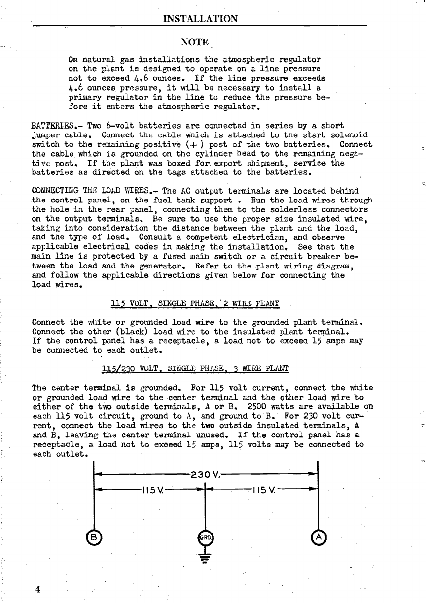
Connecting
the
Load Wires - - - - - - - - - - - - - - - -
Preparation
Lubrication
- - - - - - - - - - - - - - - - - - - - - - -
Fuel,
Gasoline -
Natural
Gas
or
LPG
- - - - - - - - - - -
Radiator
-
-:-
- - - - - - - - - - - -
.,.
- - - - - - -
Operation
Preliminary
- - - - - - - - - - - - - - - - - - - - - - -
Starting
the
Plant
Electrically
- - - -
--
- - - - -
--
starting
the
Plant
Manually - - - - - - - - - - - - - - -
Checking
the
Operation - - - - - - - - - - - - - - - - - -
stopping
the
Plant
- - - - - - - - -
--
- - - - - - - - -
Abno~al
Operating Conditions
Low
Temperatures - - - - - - -
-'-
- - - - - - - - -
---
High Temperatures - - - - - - - - - - - - - - - - - - - -
Dust and
Dirt
- - - - - - - - - - - - - - - - - - - - - -
Periodic
Service
Daily ,Service - - -
-.-
- - - - - - - -
--
- - - - - - -
Weekly
Service-
- - - - - - - - - - - - - - - - - - - - -
Monthly
Service
--
- -
-,-
- - - - - - - - - - - - - - -
Six
Monthly
Service
- - - - - - - - - - - - _
---
Adjustments
Carburetor,
Gasoline -
Carburetor,
Gas
or
Vapor -----
Electric
Choke
-Sisson
Choke
- - - - - -
~
- - - - - - -
Governor - - - - - - - - - - - - - - - - - - - - - - - -
High
Water Temperature Switch - - - - - -
'-~
- - - -
--
Fan
Belt
Tension - - - - - - - - - - - - ...:- - - - - - - -
Kaintenance and Repair
Engine
--
- - - - - - - - - - - - - - - - - - - - - - - -
Table
Qf
Clearances - - - - - -
--
- - - - - - - - - - -
Generator - - - - - - - - - - - - - - - - - - - - - - - -
Controls - - - - - - - - - - - - - - -
~
- - - - - - - - -
Service
Diagnosis
Possible
Cause -
Remedy
- - - - - - - - - - - - - - - - -
Instructions
for
Ordering
Repair
Parts
- - - -
~
- - - - - -
Repair
Parts
List
- -
..:
- - -
.;..
- - - - - - - - - - - - - - -
Supplement
for
Direct
Curr~t
Plants
PAGE
NO.
1
',')
2
2
2
3
3
:3
4
4
7
8
,8
9
9
9
10
II
12
13
13
14
14
15
16
17
17
19
20
20
21
27
29
30
.31
39
52
67