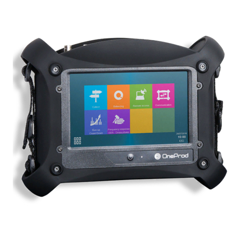
OneProd MVX User manual

MVX
User Manual
MVX
User Manual


www.acoemgroup.com
Copyright ©
This document is the property of 01dB-Metravib. No part of this publication may be duplicated,
reprinted or transmitted by electronic, mechanical, photographic or other means, or recorded,
translated, edited, abridged or expanded without the prior written consent of the owner
Reference Document : DOC3021
Date : December 2015
Revision : F
Name : MVX User Manual
MVX
User Manual

Table of contents
1Introduction ....................................................................................................... 7
1.1 Hazardous areas.......................................................................................... 7
1.2 Installation.................................................................................................... 7
1.3 Version compatibility .................................................................................... 8
1.4 Hardware identification................................................................................. 9
2Evolutions........................................................................................................ 10
2.1 Main evolutions of firmware version 5.4.0-7............................................... 10
2.2 Main evolutions of MVX version 5.1........................................................... 10
2.3 Main evolutions of MVX version 5.0........................................................... 10
2.3.1 Monitoring on 100% of the signal........................................................ 10
2.3.2 “Time waves on event” signals recording............................................ 13
2.3.3 DAT option performance optimisation................................................. 14
2.3.4 BGI: for the monitoring of structures ................................................... 14
2.3.5 GCI: for particle counting..................................................................... 14
2.4 Main evolutions of MVX version 4.............................................................. 15
2.4.1 New « Shock FinderTM » indicator (SFI)............................................. 15
2.4.2 Increase of the efficiency..................................................................... 16
2.5 Main evolutions of MVX version 3.1........................................................... 16
2.5.1 Compatibility with the ESA analysis by ONEPROD-System ............... 16
2.5.2 Short-term memory ............................................................................. 16
2.5.3 OPC parameters via XCOM................................................................ 17
2.5.4 Priority management........................................................................... 17
2.5.5 Alarm triggering delay ......................................................................... 17
2.5.6 Vector tracking.................................................................................... 18
3MVX Operating................................................................................................. 19
3.1 Principle ..................................................................................................... 19
3.2 Operating conditions .................................................................................. 19
3.3 Operating in “Monitoring” mode.................................................................. 19
3.4 Operating in “Predictive Maintenance” mode ............................................. 20
4Set-up............................................................................................................... 21
4.1 Setup with OneProd CSM.......................................................................... 21
4.2 Set-up with ONEPROD XPR...................................................................... 21

5Indicator lights on the front panel.................................................................. 22
6Connecting MVX on an Ethernet network ..................................................... 23
6.1 Ethernet port selection ............................................................................... 23
6.2 IP addressing mode ................................................................................... 24
6.2.1 Default address mode......................................................................... 24
6.2.2 MVX dynamic address mode .............................................................. 25
6.2.3 MVX fixed address mode.................................................................... 25
6.3 How to check the Ethernet connection....................................................... 26
6.4 Examples ................................................................................................... 27
6.4.1 Connecting one MVX with one PC in a point to point connection through
the MVX right port.............................................................................................. 27
6.4.2 Two MVX and two PC connected together as a “local network”.......... 28
6.5 MVX Web interface .................................................................................... 29
7Using the MODBUS output interface ............................................................. 30
7.1 General points............................................................................................ 30
7.2 Communication principles .......................................................................... 30
7.2.1 Serial MODBUS with RS485 connection............................................. 30
7.2.2 MODBUS-TCP with Ethernet connection............................................ 31
7.3 Data format................................................................................................. 31
7.3.1 Available indicators............................................................................. 31
7.3.2 Modbus requests................................................................................. 32
7.3.3 Number of indicators........................................................................... 32
7.3.4 Values of indicators............................................................................. 32
7.3.5 Status of indicators.............................................................................. 33
7.3.6 Units of indicators................................................................................ 34
7.3.7 Threshold values................................................................................. 35
7.3.8 Values of operating parameters.......................................................... 37
8Maintenance..................................................................................................... 38
8.1 Preventive maintenance operations........................................................... 38
8.2 Replacement of the battery........................................................................ 38
8.3 1st level diagnosis....................................................................................... 38
8.3.1 Normal boot sequence........................................................................ 38
8.3.2 Regular working operations................................................................. 39
8.3.3 Bias voltage monitoring....................................................................... 39
8.3.4 Offset compensation ........................................................................... 39

8.3.5 Defects indicated by the MVX leds...................................................... 39
8.3.6 Summary............................................................................................. 41
8.4 MVX Hard Reset ........................................................................................ 42
8.5 MVX Firmware upgrade ............................................................................. 42

7
Brand of ACOEM
1 Introduction
Thank you for purchasing the ONEPROD MVX monitoring and predictive
maintenance system.
This performing system allows for the monitoring of industrial machines using 8, 16,
24 or 32 measurement channels, depending on the selected model.
ONEPROD MVX can also act as a synchronous multichannel acquisition system
when connected to a predictive maintenance platform based on the ONEPROD
NEST ANALYST (XPR) software package.
ONEPROD MVX can be connected to many transducers, even though its prime
objective remains vibration measurement and analysis.
In case of a problem, please contact OneProd Hotline:
oneprod.support@acoemgroup.com
1.1 Hazardous areas
WARNING
REFER TO INSTALLATION MANUAL BEFORE ANY INSTALLATION IN A HAZARDOUS
AREA.
SEE DOC3012 2015-12 G or later.
1.2 Installation
See the dedicated manual for MVX Installation:
DOC3012

8
Brand of ACOEM
1.3 Version compatibility
The following combinations must be fulfilled in order to guarantee an optimal working.
Release date / MVX type
MVX
(firmware)
CAST
CSM
VIO
XPR
Until September 2007
1.0xx
1.01.xx
1.00x
1.00x
3.05
From October 2007
2.0xx
2.xx
2.xx
2.xx
4.xx
From October 2009
3.1.xx
3.1.xx
3.0.xx
2.0.x
4.1.x
From Novembre 2009
4.1.xx
3.2.x
3.0.xx
2.0.x
4.3.x
From January 2011
(restrained diffusion)
4.2.xx
3.4.3
3.0.xx
2.0.x
4.4.1
From June 2011
5.0x
3.4.9
5.0.xx
5.0.x
4.5.x
From June 2013
MVX1001000 type
MVX1002000 type
5.1.0-1
3.5.3
5.0.4
5.0.4
4.6.0
ONLY FOR :
MVX1027000
5.1.0-2
3.5.4
5.0.4
5.0.4
4.6.5
ONLY FOR :
MVX1027000A
MVX1027000B
MVX1029000
MVX1031000
5.4.0-7
3.7.3
-
-
4.6.7

9
Brand of ACOEM
1.4 Hardware identification
Year after year, MVX Hardware supported some changes.
The hardware version of each MVX is available on the side label that is pasted on the
left side, just near the fan entry.
The following table gives the technical differences between the hardware versions:
Type
Maximum
number of
channels
Compatibility
ATEX Zone 2
(or Cl.1-Div2)
RAM
Original operating
system
MVX1001000
16
NO
256 Mo(2)
WinCE (1)
MVX1002000
32
NO
256 Mo(2)
WinCE (1)
MVX1001000A
16
YES
256 Mo(2)
WinCE (1)
MVX1002000A
32
YES
256 Mo(2)
WinCE (1)
MVX1001000B
16
YES
512 Mo
Linux
MVX1002000B
32
YES
512 Mo
Linux
MVX1001000C
16
YES
512 Mo
Linux
MVX1002000C
32
YES
512 Mo
Linux
MVX1001000D
16
YES
512 Mo
Linux
MVX1002000D
32
YES
512 Mo
Linux
MVX1001000E
16
YES
512 Mo
Linux
MVX1002000E
32
YES
512 Mo
Linux
MVX1027000
MVX1027000A
MVX1027000B
16
NO
1 Go
Linux
MVX1029000
32
NO
1 Go
Linux
MVX1031000
16
YES
1 Go
Linux
(1): Upgrade of WinCE is not supported anymore.
(2): Upgrading RAM is NOT possible

10
Brand of ACOEM
2 Evolutions
2.1 Main evolutions of firmware version 5.4.0-7
WARNING : This firmware version is ONLY for MVX 1027000A, MVX1027000B,
MVX1029000 and MVX1031000.
Firmware update through the MVX Web interface (not CAST anymore).
Operating conditions management: only 1 operating condition can be valid at a
time. If more than 1 operating condition is valid, MVX takes the first valid
condition of the list (list from XPR operating condition pannel)
Improved definition of operating condition limits :
oLow limit included(≥), high limit exclude (>)
Operating conditions can be available by OPC or by Modbus, not both at the
same time.
Possibility to disable automatic reset in case of bad configuration in remote
locations
2.2 Main evolutions of MVX version 5.1
Modbus Digital Inputs: Refer XPR software user manual to see the
implementation of this feature. This mode cannot be used with CSM
The operating parameters are available through MVX Modbus output: cf. §
7.3.8
New management Ethernet ports: cf. § 6
2.3 Main evolutions of MVX version 5.0
2.3.1 Monitoring on 100% of the signal
This new functionality is available only on Premium MVX version
From V5.0.xx version MVX Premium is able to compute in real time a selection of
indicators. The aim of such a function consists in ensuring that 100% of the signal is
actually monitored.

11
Brand of ACOEM
Illustration:
“Standard” indicators are achieved at each cycle by MVX.
Thus, a very short phenomenon can be ignored if it happens during a processing
phase.
RT indicators (Real Time) are achieved permanently during acquisition
Thus, 100% of the signal is actually monitored.
Thus the smallest transient phenomena can be detected (even if it happens only
once and if it lasts some milliseconds), according adapted parameters (i.e. pick
detection).
Besides it is obVIOusly possible to choose another set of parameters, which erases
transient phenomena in order to avoid false alerts (i.e. RMS detection with several
seconds time constant).
As a complement to such real time monitoring, MVX can record a new “Time waves
on event” signal category (Please see next §).
The following processing parameters can be applied to define real time indicators
which are monitored on 100% of the signals.
High pass filter : 2Hz or 10Hz
Signal integration : 0 or 1
Low pass filter : 1000Hz or no filter (i.e.20kHz)
Processing : RMS, pk or pk-pk
Averaging : continuous exponential with time constant between 1s and 25s
Averaged DC level (for process and GAP signals)
BGI indicator (Blade Guard Index)
GCI indicator (Gearbox Condition Index, see next §)
Broad band and narrow band extraction on real time FFT :
oFFT 400 pts, 800 pts, 1600 pts ou 3200 pts
oFFT 1kHz, 2kHz, 5kHz, 10kHz ou 20kHz,
oFFT with 50% fixed overlapping
1 cycle
Acquisition
Processing
Processing
Processing
Acquisition
Acquisition
t
Acq. 1
Proc. 1
t
Acq. 2
Acq. 3
Acq. 4
Acq. 5
Acq. 6
Proc. 2
Proc. 3
Proc. 4
Proc. 5
Proc. 6

12
Brand of ACOEM
Real time indicators are achieved in the limit of the available MVX processing
capability.
An automatic control of the parameters embeds a checking of MVX processing load
and cautions the operator when launching if overload is predictable.

13
Brand of ACOEM
2.3.2 “Time waves on event” signals recording
MVX Premium with DAT option is required
Besides real time monitoring MVX can record specific time waves that can be trigged
at all time and that includes « pre-trigger » capability. I.e. possibility to include what
happened BEFORE the trigger event.
Possible trigger events:
oReal time indicator alarm level VIOlation,
oChange in the operating condition,
oManual measurement request (from XPR)
Time wave on event parameters:
oFixed sampling rate: 51.2 kHz.
oLength: 1s to 30s on 32 channels
oMaximum length can be overstepped if less than 32 channels have
to be recorded at the same time:
Number of channels concerned by time wave on event
32
24
16
8
4
3
2
1
Maximum duration (s)
30
40
60
120
240
320
480
480
Pre-trigger duration: 0 to total wave length (*).
(*) For first generation MVX which have been updated with V5.xx, the following
limitations (due to internal RAM) are to be considered:
To know if your product is affected please have a look on §12
t
Real Time Parameter
Alarm threshold
Time wave on event
Pre-trigger
Total time wave duration
Event

14
Brand of ACOEM
Complementary limitations, only for 1st generation MVX
Number of channels with Time wave on event
32
24
16
8
4
3
2
1
Maximal duration (in s) with pre-trigger = 0
30
40
60
120
240
320
480
480
Maximal duration (in s) with pre-trigger = full length
9
13
19
39
78
117
156
156
Note: Internal RAM cannot be upgraded.
2.3.3 DAT option performance optimisation
Firmware version 5.0.x.x improves substantially DAT performance in optimizing RAM
management in two directions:
Limiting RAM consumption for a given configuration
Involving the additional RAM that is available on the last generation products (Please
see §12)
2.3.4 BGI: for the monitoring of structures
BGI = Blade Guard Index.
BGI is a specific indicator, dedicated to monitor structural resonance phenomena. It
can be particularly suitable for wind turbine blades when associated to specific
sensors.
BGI requires DAT option in order to get time wave on alarm signal.
2.3.5 GCI: for particle counting
GCI (Gearbox Condition Index) is dedicated to particles counting.
GCI is available with MVX Easy or Premium.
Particle sensor (i.e. GASTOPS / MetalSCAN) are especially useful for degradations
of the wind turbine gearboxes.
GCI is performed on 100% of time.
GCI is made with 3 sub-indicators:
GCI-h : number of particle detected in the last hour
GCI-d : number of particle detected in the last 24 hours (performed in a
slipping mode)
GCI-t : Total number of detected particle
Each sub-indicator is monitored with its own set of thresholds.

15
Brand of ACOEM
2.4 Main evolutions of MVX version 4
In addition to the new functions described in the preVIOus chapter, Version #4.1 of
the MVX firmware includes the following evolutions:
2.4.1 New « Shock FinderTM » indicator (SFI)
This new indicator is able to detect abnormal shocks<;
It is especially suitable for low speed machineries, where standard indicators (i.e.
filtered RMS vlalues) are not always completely pertinent
Thus Shock FinderTM is suitable for windturbine rotor monitoring, steelmill or
papermill monitoring, etc.
It can be used for rolling element bearings as well as gearbox monitoring.
Shock FinderTM also incorporates a smooth function dedicated for decreasing false
alarm risk.
Please consult XPR300 V4.3 user manual (chapter 14.8) for more details about SFI
set up.
Shock FinderTM can be setup with ONEPROD NEST ANALYST (XPR)
Shock FinderTM can’t be setup with OneProd CSM

16
Brand of ACOEM
2.4.2 Increase of the efficiency
MVX firmware V4.1 is based on a new operating system. Consequently MVX
efficiency is increased.
The main observable improvement concerns the processing times that are lower vs
preVIOus firmware versions.
Consequently a decrease of the cycle time is observed, allowing an improvement of
the monitoring rate.
2.5 Main evolutions of MVX version 3.1
Version 3.1xxx of the MVX firmware includes mainly the following new functions:
2.5.1 Compatibility with the ESA analysis by ONEPROD-
System
MVX is now compatible with the electric signal analysis (ESA) functions available in
ONEPROD NEST ANALYST (XPR).
The analysis of electric signals consists in acquiring and analysing the power supply
voltages and currents of a motor and detecting the distinctive characteristics thereof
that indicate anomalies.
Electric or mechanical anomalies on the motor can thus be evidenced (unbalance,
misalignment, broken bar, etc.).
2.5.2 Short-term memory
MVX stored in a FIFO buffer all or part of the indicators that were worked out during
the monitoring measurements.
MVX can store up to 1000 values for each indicator, with a periodicity ranging from a
few seconds (*) to 600 seconds.
This new function is available from ONEPROD NEST ANALYST (XPR) only.

17
Brand of ACOEM
(*): for a given application, the periodicity cannot be shorter than that for the
calculation of the indicators by MVX.
Example:
When an indicator goes into alarm mode, one can know whether this indicator
increased suddenly or progressively before reaching the alarm threshold.
2.5.3 OPC parameters via XCOM
When MVX is connected to XCOM (communication engine of ONEPROD NEST
ANALYST (XPR)), it can now:
Monitor original OPC parameters (*)
Use original OPC parameters (*), such as condition parameters
(*): MVX does not have a local OPC connection. Parameters called “original OPC
parameters” are retrieved by the OPC client of the XCOM component, which is
physically located on the same PC as ONEPROD NEST ANALYST (XPR)
2.5.4 Priority management
MVX can now take into account three possible priority levels for each task.
This function allows for a better monitoring of machines with complex or random
operating conditions.
2.5.5 Alarm triggering delay
The purpose of this function is to avoid untimely alarms due to interference or
transient phenomena (e.g., related to the start of a neighbouring machine). It consists
in, on request, acknowledging an alarm status ONLY if it is confirmed during a given
period.
This function is accessible only from ONEPROD NEST ANALYST (XPR). A
triggering delay is defined in seconds. If it is shorter than the cycling time, MVX
performs at least one confirmation measurement.

18
Brand of ACOEM
MVX keeps it operating cycle and must confirm the presence of the alarm on all
measurements collected over the defined time.
If the alarm level remains present during the defined time, MVX triggers the alarm
status: relay, MODBUS status, acquisition on status change. If the level disappears,
the alarm is no longer effective.
2.5.6 Vector tracking
MVX can now, and on request from ONEPROD NEST ANALYST (XPR), calculate
phased spectra.
The phase reference that is taken into account is that of the trigger input
corresponding to the machine under study.

19
Brand of ACOEM
3 MVX Operating
3.1 Principle
Unlike most predictive maintenance system on the market, ONEPROD MVX
performs sequences of simultaneous acquisitions on all measurement channels.
These acquisitions are really synchronous and in phase.
3.2 Operating conditions
Signal acquisitions can be performed (depending on the configuration) under specific
operating conditions for the machine(s) under monitoring.
These operating conditions can be:
A rotation speed, acquired by MVX through a “trigger input”-type frequency
signal connected to one of the analogue inputs.
Values of one or two process parameters (power, temperature, etc.) acquired
by MVX one of the analogue inputs through a continuous voltage or 4-20 mA
current signal.
Up two 3 logical data (TTL signal) acquired by MVX on its logical inputs.
3.3 Operating in “Monitoring” mode
When MVX is set up to perform monitoring operations, the processing of data
acquired simultaneously aims at calculating indicators and comparing them to alarm
thresholds.
This calculation is performed:
During acquisition for the real time indicators (MVX Premium only)
After each acquisition phase for the standard indicators.
Thus, MVX alternates acquisition and processing phases and a set of updated
“results” indicators is available after each processing phase.

20
Brand of ACOEM
Spectra calculated for the extraction of indicators can neither be viewed nor stored by
MVX.
3.4 Operating in “Predictive Maintenance” mode
When MVX is set up to perform predictive maintenance tasks, it performs the
required acquisition(s) as soon as the fixed period or date has expired.
In this case, all signals (spectra and/or time signals) and indicators described in the
configuration are stored by MVX in order to be integrated into the predictive
maintenance database, either at once, or later on.
Between two scheduled operations, MVX can permanently calculate scalar indicators
described in the settings and compare them to alarm thresholds, like in the
monitoring mode.
In case of status change (threshold VIOlation), all measurements (spectra and/or
time signals) and indicators described in the parameter settings are stored by MVX to
be later integrated to the predictive maintenance database.
Short-term memory:
Furthermore, and for each calculated parameter, MVX will store in a FIFO buffer the
short-term history of scalar values.
The size of this FIFO buffer can be set up to 1000 values per indicators.
The periodicity for storage in the short term memory can also be programmed and
can range from a few seconds (i.e., MVX stores all calculated values) to 600 s.
By storing 1000 values with a periodicity of 600s, the capacity of this short-term
memory can thus reach 600 000s, i.e., about 1 week.
Other manuals for MVX
1
Table of contents
Other OneProd Measuring Instrument manuals
Popular Measuring Instrument manuals by other brands

Nic
Nic EMP-2 Simplified manual

Maximum
Maximum NOR’EASTER installation manual

Extech Instruments
Extech Instruments 407113 user guide

EUTECH INSTRUMENTS
EUTECH INSTRUMENTS CYBERSCAN PH500 PHORP BENCH METER Manuel d'instructions

Vega
Vega VEGABAR 52 operating instructions

Geokon
Geokon 6350 installation manual

VELOCICALC
VELOCICALC 5725 Operation and service manual

Agilent Technologies
Agilent Technologies 4100 Operation manual

RigExpert
RigExpert AA-200 user manual

Profimess
Profimess SW-03 Air operating instructions

KSR KUEBLER
KSR KUEBLER BNA EX Series Mounting and operating instructions

Agilent Technologies
Agilent Technologies U5303A Startup guide