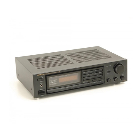
Onkyo A-7022 User manual

SERIAL
NO.
3006
ONKYO
SERVICE
MANUAL
OLID
STATE
STEREO
PRE
MAIN
AMPLIFIER
model
A-7022
UDO
COMPOREN

SPECIFICATIONS
Main
Amplifier
Section
Power
Output
Dynamic
200W
(THF
42)
150W
(IHF
8Q)
72W
+72W
(4Q
both
channel
driven}
65W
/65W
(8Q
each
channel
driven)
52W
+
52W
(8Q
both
channel
driven)
Continuous
Total
Harmonic
Distortion
0.1%
at
Rated
Output
0.03%,
at
1OW
Output
Inter
Modulation
Distortion
0.05%
at
Rated
Output
Power
Bandwidth
10-100,
000Hz(-3dB
THD
0.2%)
Signal
to
Noise
Ratio
110dB(IHF
A
NETWORK)
Damping
Factor
80
at
8
Rated
Input
and
Impedance
1V/100kQ
Load
Impedance
4-16Q
Pre
Amplifier
Section
{
i
PHONO-1/~2:1.
2/2.
4/4.
8mV
(50kQ)|
Inputs
TUNER,
AUX,
TAPE
PLAY:
Input
Sensitivity
100mV
(100k)
Total
Harmonic
Distortion
0.03%at
Rated
Output
Intermodulation
Distortion
0.05%
at
Rated
Output
Outputs
RIAA
Deviation
Phono
Overload
+0.
5dB
(30-15,
000Hz
)
300mV
RMS
at
1kHz,1.4V
RMS
at
10kHz
PHONO
-1/-2:75dB(THF
A
NETWORK)
TUNER/AUX:90dB(IHF
A
NETWORK)
Signal
to
Noise
Ratio
Features
Output
Voltage
1V
Tone
Control]
with
2dB/step
Switch
and
Frequency
Shift
type
BASS
:400/125Hz
TREBLE:
2k/8kHz
Frequency
Shift
Bass
Control
Treble
Control
+5
steps
Boost
and
Cut
+5
steps
Boost
and
Cut
Filter
HIGH
8kHz(6dB
/oct.
)
LOW
30Hz
(6dB
/
oct.
)
!
Muting
~20dB
,
Power
Supply
Rating
Loudness
+5dB
at
70Hz,
+5dB
at
10kHz
,
Semiconductors
Controls
POWER
SPEAKERS
(OFF,
A, B,
A+B)
SELECTOR(
AUX,
TUNER,
PHONO
1,
PHONO
2,
MIC)
Weight
TAPE
MONITOR(PRINT
1-2,
TAPE-1,
SOURCE,
TAPE-2,
PRINT
2-1)
Dimensions
MODE(REV,
NORM,
R+L,
L,
R)
VOLUME/BALANCE
TREBLE
BASS
FREQUENCY
SHIFT
SWITCH
BASS
(400Hz,
125Hz)
TREBLE(2kHz,
8kHz!
MUTING
LOUDNESS
FILTER
HIGH
LOW
PHONO
SENSITIVITY
(1.2/2.
4/4. 8mV)
PRE
MAIN
SEPARABLE
SWITCH(UNITE-SEPARATE)
PHONO-1,
PHONO-2,
TUNER,
AUX,
MIC
L/R
TAPE
PLAY-1,
TAPE
PLAY-2,
MAIN
IN
SPEAKER-A,
SPEAKER-B
TAPE
REC-1,
TAPE
REC-2
PRE
OUT
AC
OUTLET
UNS
WITCHED,
SWITCHED
x2
PHONES
2
Phono
inputs
2
Tape
Monitor
and
Printing
2dB
Step
Tone
Controller
2
Choice
of
Turn
over
Frequency
ASO
type
protection
circuit
Transient
Killer
circuit
Main
Amplifier
incorporating
OCL
circuit
MIC
input
Big
Phono
Overload
ac
110/120/220/240V
50/60Hz
44
Transistors,
30
Diodes,
2
Thermistors
16
5/8°W
x
53/8"H
x
14
3/4"D
423mm
W
x
136mm
H
x
373mm
D
10.5kgr,
23lbs

1.
COMPONENT
LOCATIONS
DESCRIPTION DESCRIPTION
Amp
Box
assembly
Soft
Block
Front
Fiber
Board
Front
Cover
Eind
Cap
Flat
Screw(3S
+5F)
Joiner
Pan
head
Screw(3P+8F)
Knob—Push
Switch
Binder
Screw(3+6)
Knob—
Tone
Front
Panel
Facet
Knob—
Volume
Knob
—Balance
Knob
Sheet
Knob—
Selector
Rubber
Cushion
Tapping
Screw(4+12)
Bottom
Cover
Chassis
Toothed
Lock
Washer
Truss
Screw(4+20)
Soft
Block
Knob
Guide
Knob
—
Tape
Facet
Ring
Concave
Washer
Knob
—
Speaker

2.
ADJUSTMENT
OF
THE
IDLING
CURRENT
[40.5
cos
+6
|
Re
Ray
220/63
ae
|
R329
0301
R328
aio
~----,
Reh.
Q305
1%
8
(21)
—
0327
;
KS)
as
P
Q311.0"
0.047
LS
-
+13
0,
0
1
kK)
2
ty?
]
O71
30
10P/500
100
rat
Et
R319
—N,
=
22K
Rad7
1
AJ
(1/2
|
R367
TRL
a
($23,
R369
68
(17
2)
CO
33725
ca
yenmoss
Gum
jeouT
LO
£50my
R307
KU
0.047
ie
680
R321
L301
1apH
fe
#313
339
R309
100
/
30
|
-
mov)
‘@
Q005
6.067
0309
Scar
»
Yas
(i)
|
W2-210
|
5
‘sp.
R323
R369
0307
SS
ax4
\-24V
4.7K
SS
ELK
S471
6
Q3
(172)
1472)
[~4.3¥]
30P
IN6O
R339
5329
l
R371
333
:
22k
=
D311
01
R325
D305
wv?)
(172)
1001
680
191555
l
re
1K)
“8
ool
OE
(nau
7470/50
|
Rech
LoL
ORO
_t
Instrument
required
:
DC
Ammeter
50mA
or
100mA.
DC
Voltmeter
50mV
or
VTVM.
When
replacing
the
POWER
transistor
(Q003,
Q004,
Q005,
Q006)
or
the
DRIVER
transistor
(Q311,
Q312,
Q313,
Q314),
check
the
idling
current
of
the
POWER
transistor.
To
adjust
to
normal
value
(40+5)mA,
proceed
as
follows.
(Leh)
(1)
Cut
the
connection
between
+B
and
collector
of
Q003
on
MAIN
Amp
assembly,
and
connect
a
DC
Ammeter.
(2)
Adjust
the
current
to
(40+5)mA,
with
R319(2.2kQ)
after
switching
on
for
10
minutes.
(3)
After
adjusting,
connect
original
wiring.
If
a
DC
Voltmeter
(50mV)
or
VIVM
is
available,
connect
the
Voltmeter
betweenE]
and
TP
terminals.
Adjust
the
voltage
to
(20+2.5)mV
with
R319(2.2kQ).
(Rech)
Using
R320(2.2kQ),
adjust
in
the
same
manner
as
indicated
above.
*
Note:
Volume—Minimum.
Open
Load.
3.
PARTS
LIST
DESCRIPTION
SPECIFICATION
|Q’TY|
STOCK
NO.
Equalizer
Amp
ass’y
NAEQ-206
12939506
Tone
Amp
ass’y
NATC-186b
12939586B
Main
Amp
ass’y
NAMA~187a
12939587A
Power
Supply
ass’y
NAFI-207
12939507
Protector
ass’y
NAPC-208
12939508
Transistor
25C945(P)
2210353
ZSD¢27
25
D218(M
2200042
2200142
25899
/

PARTS
NO.
DESCRIPTION
SPECIFICATION
(QTY
STOCK
NO.
PL0O1
Pilot
Lamp
6.3V0.15A
1
210003
T001
Transformer-Power
NPT-552ADGQ
1
230056
ore
Capacitor-Electrolytic
CE62W50V8200uF
2
|
3504035A
CE04W50V33uF
2
|
325783301A
C305,
306
|
Capacitor-SP
SP04C25V2.
2uF
4
|
392250229
cea8
V
SP04C25V10uF
2
Volume
RO15
Variable
Resistor
N24RDGSOOKMN250KB2T
|
1
|
5104006
Balance
S001
S
witch-Rotaly
NRS-385-20Y
1
|
250165-1
Selector
S003
"
NRS~465-15Y
1
|
350175-2
Tape
Monitor
S004
"
NRS-125-15Y
1
250180-1
Mode
S008,
S009
”
NRS-2211-20Yb
2
250117
Tone
S013
¥
NRS-124-20Y
1
250118-1
Speakers
S002
Switch-Slide
NSS-2323
1
|
250121
Phono
Sens
S012
"
NSS-4224
1
250122
Pre
Main
$005,010
Switch—Lever
NLS-122-29S
L
4
|
2501191
Mvtng
adness
S006,
007
y
NLS~-142-29S
L 2
|
250120-1
Frequency
Shift
S01
S
witch-Power
NPS111LA2
1
|
250157
S015
Klixon
9700L-26-11
1
|
252009
S016
"
9700L-21-11
1
|
252011
Jack-Stereo
Head
Phone
3P64M
1
250126
Jack-Microphone
HJ-631S-H-3
2
|
250176~1
F001
Fuse
1.5A-T
1
|
252015
F002
"
2A-T
1
|
252002
Amp
Box
ass’y
1
|
280762
Front
Panel
1
|
280759
End
Cap
2
280367
Facet
1
|
280556
Joiner
4
|
280376
Knob-Tone
2
|
283085
Knob-Selector
1
|
283086
Knob-Volume
1
|
283087
Knob-Balance
1
|
283088
Knob-S
peaker
1
283096
Knob-Tape
ass'y
2
283103
Knob-Power
1
283071
Bottom
Cover
1
270295
Rubber
Cushion
4
|
280379
Master
Carton
Box
1
290378
Side
Pad
2
|
290203-1
NATC-186b
OO
Q201~
Q204'
Transistor
—
25
A493(GR)
4
|
2210235
=|
_
Q205,
Q206
”
25C1000(0-1)
2
|
2210280
Q207,
Q208
|
"
25C733(GR)
2
|
2210085
Q209
"
2SC734(0-1)
1
|
2210060
D201,
D203
|
Silicon
Diode
1S1554
2
|
223106
C201,C202
Capacitor-Electrolytic
CE04W
25V0.
47uF
2
|
352754791A
C205,
C206
q
CE04W6.
3V100uF
2
|
352721011A
C203,
C204
|
n
CE04W35V220uF
1
|
352762211A
C229
~
C232
SP04C25V2.2uF(M)
4
3500023
Capacitor-SP

Relay
PARTS
NO.
DESCRIPTION
SPECIFICATION
(Q’TY|
STOCK
NO.
C233~
C234]
Capacitor-SNP
|
SNP04C25V22uF(M)
|
2
|
3500027
y
|
»
2.2uF(M)
2
|
3500025
NAMA-187a
-
Q301~
Q304|
Transistor
25C€1000(0-1)
4
|
2210280
313
Q314
”
2S
A706(52)
4
|
2200032
Q307,
Q308
y
2SC735(GR)
2
|
2210245
Q309,
Q310
|
»
25
A562(GR)
2»
2210255
Q311,
Q312
y
25C1124(2)
2
2200016
Paes,
Dane
|
Silicon
Diode
1$1555
4
|
223105
D311
1
10D1
1
|
223801
Dag”
Daog
|
Germanium
Diode
1N60(N)FM
4
|
2231031
D309
Zener
Diode
W
Z-210
1
|
223921
1.301,
L302
Coil-Load
Compensation
S-1.
3B
2
231001
C309,
C310
Capacitor-Electrolytic
CE04W
6.
3V220uF
2
|
352722211A
C341
"
"
50V470uF
|
1
|
352784711A
R319,
R320
|
Resistor-Semi
Fixed
R-HK2.
2KB
2
|
5225005
TH301,
TH302
|
Thermistor
D-22A
|
2
|
4000003
NAEQ-206
Q101,
Q102
|
Transistor
2SA493(GR)
2
2210235
Q103,
Q104
|
n
2SC1000(0-1)
|
2
|
2210280
Q105,
Q106
|
"
2SC1124(3)
2
|
2200101
D101,
D102
Silicon
Diode
181555
2
223105
Capacitor—Electrolytic
CE04W
16V47uF
2
352744701A
"
”
6,3V220uF
2
|
352722211A
" »
25V100uF
3
|
352751011A
C101,
C102
|
Capacitor-SP
SP04C25V2.
2uF
2
|
3500023
C125,
C126
"
"
10uF
2
}
3500024
NAFI-207
-
Q401,Q407
Transistor
25D234(0)
2
|
2200113
|
Q403—
|
"
2SA561(0)
1
|
2210073
Q405
”
25C945(P)
1
|
2210353
D403
Silicon
Diode
10DC2R
1
|
223813
D405
"
10D1
1
|
223801
D401
Zener
Diode
|
WZ-270
1
|
223922
NAPC-208
Q501.
|
Transistor
25C945(P)
"1
|
200353
=]
Q503
n
2$C945(Q)
1
|
2210354
Q505
"
2SD235
|
1
|
2200013
Q507,
Q509
|
4
2S
C634A
(70)
2
|
2210187
Dae’
Deis
|
Silicon
Diode
10D1
4
223801
D523)
D525
'
SR3AM-6B
4
|
223815
Des.
Deon
|
Germanum
Diode
1N60(N)FM
4
2231031
D513
|
Zener
Diode
BZ-120
1
223918
©
C501
Capacitor-Electrolytic
CE04W25V1uF
1
|
392750101A
C503
"
»
16V100uF
1
352741011A
C505
y ”
—
1000uF
1
|
352741021A
C513,
C515
"
CE04W50V
47uF
2
|
302784701A
C521,
C523
n
»
25V220uF
2
|
392752211A
S501
NRSP5A-DC12
1
|
250166

4.
PACKING
PROCEDURE
1.
Tighten
SPEAKER
terminals
by
a
hand.
9
Clean
an
AMP
BOX
assembly,
attending
to
your
fingerprints.
Set
a
SENSITIVITY
SWITCH
to
center
(2.
4mV).
Clean
a
REAR
PANEL
and
a
RADIATOR.
Insert
SHORTED
PIN
into
PHONO
—
1,2
terminals.
Wrap
a
POWER
CORD
with
a
AC
CORD
WRAPPER
and
bind
it
with
a
rubber
band.
7.
Wrap
unit
with
a
AMP
COVER
and
attach
a
SIDE
PAD
to
both
sides.
g
Put
in
a
CARTON
BOX
and
make
sure
the
front
marks
of
the
carton
matches
the
unit
front.
9.
Put
an
ACCESSORY
BAG
including
an
INSTRUCTION
BOOKLET,
WARRANTY
CARD
ete.
in
the
box.
10.
Close
the
CARTON
BOX
and
seal.
a
oe
&
AMP
BOX
ASSEMBLY
pega
«|
©)
e)
(AON
Bi
|
eicledeicte
sf
|
Ey
|
REAR
PANEL
iSssss
">
SPEAKER
WSS
TERMINAL
Or
ern
VOLT
CAUTION
TAG
Fa
os
WRAPPE
Gv
LABEL
li
R
TRANSIENT
KILLER
TAG
SIDE
PAD

S007
LOW
FREQUENCY
SHIFT
125Hz.
400Hz
(400Hz)
$008
TREBLE
$10,
-8.-6.-4.+2.
FLAT.
«2.
24..6.+8.
«10
(FLAT)
S009
BASS
=10.-8
-6.-4.~+2,
FLAT
«2.64.
+658.
+10
(FLAT)
$010
LOW
FILTER
OFF.
ON.
a
$011
HIGH
FILTER
OFF.
ON.
(OFF
$012.
PRE-MAIN
UNITE.
SEPARATE.
(UNITE)
$013.
SPEAKERS
OFF.
A.
8
A+B.
(A)
$014
POWER
OFF.
ON.
(OFF)
$017.
LOUDNESS
OFF.
ON.
(OFF)
Qidt
284493(GR)
Q103
25C€1000
(0-2)
Q105
2501124
(3)
Q201.0203
25A493(GR)
Q205
25C
1000
(0-1)
Q207.G208
25C733(GR)
Q209
28€
734
(0-1)
Q301.
4303
28C
1000
(0-1)
Q305
254706(52)
-
Q307
2SC
735
(GR)
Q309
2SA562
(GR)
Q311
28C€1124(2)
Q313
284706
(52)
Q401
280234(0)
Q403
2S4561
(0)
405
2S8C945(P)
Q407
280234
(0)
Q501
2SC945(P)
deer
osoo
|
fseeae
90
ool
decane
aoo1
2SC945(P
Q003
2$0218(M)
Q005
at
yitit
oO
o
DC
VOLTAGE
((—¥1)
MEASURED
WITH
OC
VTVM
TO
CHASIS
AT
NO
SIGNAL
INPUT.
ALL
RESISTORS
ARE
IN
OHMS.
VGWATT
UNLESS
OTHERWISE
NOTED.
ALL
CAPACITORS
ARE
IN
pF
UNLESS
OTHERWISE
NOTED.
ELECTROLYTIC
CAPACITORS
(—-#R—)
ARE
IN
pF/Wy.
NAEQ-206
PHONO
-1
73
Sees
ie
coot
T
0047
PHONO
-2
(Q-¢———-—___—
'poos
GNO
TUNER
AUX
TAPE
-1
PLAY
@
Ww
FA
2
°
e
a)
SELECTOR
AUX.
TUNER.
PHONO-1.
PHONO-2.
MIC.(PHONO-1)
PHONO
SENS
1.2mV.
2amV.
48mV.(2.4mvV)
TAPE
MONITOR
12.
TAPE-1.
SOURCE.
TAPE-2.
2-~1.(SOURCE)
MODE
REV.
STEREO.
L.
L+R.
A.
(STEREO)
MUTING
0.
-20dB.
(0)
HIGH
FREQUENCY
SHIFT
2KHz.
8KHz.
(2KHz)
REC
73
S003
=3:fi
os
Se
aed
ee
cis
cng
00036)
O01
S064:
2R
coi?
oo
cos
O15
BASS-
UNIT
R179
150K
NATC-
186b
So
err
4+
83
R203
!
150K
'
Q201
-IN
é
R021
15M
zor
SOIT
Gen”
Lal
RO87
=
Rot
re
aoc!
$005
a
|
7
RoIS0
R017
g
SOOKMN
18K
—
nOwSe
7508
bs
te
yt
BALANCE
=
VOLUME
R601
3312)
wOOC2R
lah
Qi2/25
SP
:
aoe
7
R201
:
‘he
1M
BP
33K
;
ee
|
Fear
|
om
»
wn
Rg
C225
O01)
e
a
I
Ay
8
y
x2
"as
a
2
°
4
3
ral
bh
oo
oe
2
a8
ze
A211
Cz
i
0047
R215
C209
2.2K
at
at
Be
16
R217
1
aoee
=
@207
am
G
Digan
|
CH
E
:
4
le
_
tour
or--7
J
62
gov)
181554
pomar®
©)
PRE
-OUT
RO3)
15M
ton
=
SOT
2
5012
°
©)
MAIN-
IN
coo?
8200750
her
coos
8700/50
einen
(
I
!
‘
030)
428
181555
ra
18)
C315
3307
e)
151555
SPEAKER
-A
’
SPEAKER-
B
S016
THERMO
SWITCH
pF
$013
.
Fo
ad
a
aie
©
abo
rx)
Rech
K)
|
ee
pe
Tar
re
a
r
Wo
Ren
AD
"
ct
390(2K)
»
0517
"
:
10D1
?
'
HE
ADPHONE

7.
LINE
VOLTAGE
AND
FUSE
The
model
A—7022
operates
on
one
of
the
four
line
voltages,
110V,
120V,
220V,
and
240V.
Set
the
unit
to
the
proper
line
voltage
by
following
the
procedure
described
below.
CHANGING
LINE
VOLTAGE
SETTING
AND
FUSE
Turn
the
voltage
selector
so
that
the
proper
line
voltage
marking
can
be
seen
through
the
slot
on
the
rear
panel.
4
x
Whenever
the
position
of
the
selector
is
changed,
check
the
rating
of
the
fuse.
4)
op
~
A
2A
fuse
is
to
be
used
for
either
220V
or
240V
operation
and
a
4A
fuse
for
110V
or
120V
operation.
25h
(6
YC
Ge
WH
GE
é
(dow
—_
oeanas
(uP)
“
i
*
N
cr
~P
Other manuals for A-7022
3
Table of contents
Other Onkyo Amplifier manuals

Onkyo
Onkyo A-9711 User manual

Onkyo
Onkyo A-807 User manual

Onkyo
Onkyo M-5160 User manual

Onkyo
Onkyo TX-SV909PRO User manual

Onkyo
Onkyo TX-SV727 User manual

Onkyo
Onkyo DAC-HA300 User manual

Onkyo
Onkyo A-809 User manual

Onkyo
Onkyo 9555 - A Amplifier User manual

Onkyo
Onkyo A-8015 User manual

Onkyo
Onkyo DAC-HA200 User manual
Popular Amplifier manuals by other brands

JDS Uniphase
JDS Uniphase MAP EDFA OAB 1550 user manual

Mapletree
Mapletree Ultra 4B SE user manual

Balanced Audio Technology
Balanced Audio Technology VK-60SE owner's manual

Precision Power
Precision Power D1000/1 owner's manual

BARO
BARO BR-300A user manual

Harman Kardon
Harman Kardon CITATION 21 owner's manual