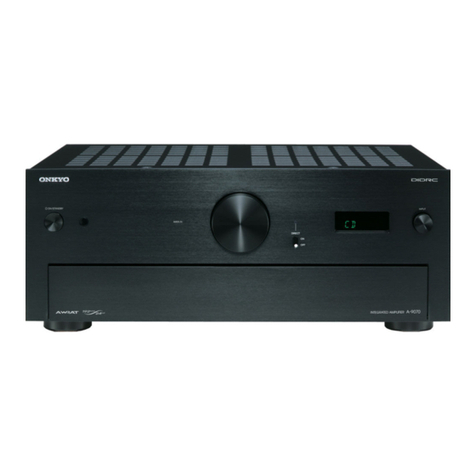
Onkyo TX-SV525 User manual

Artistry
in
Sound
ONKYO.
udio
Video
Control
Tuner
Amplifier
X-SV525
A-SVS25K
Instruction
Manual
ONEBYWO
suo
obo
CoAT
AO
TUNER
AW,
GE
QL
ONAN
ESS
a
OE
Mae
A0DE
:
Ta
Re
»SOULCE
........,.18
#
a
A
Fee
e
ETE
EY
PEN
wd
eeees
32
.

Thank
Y
OU
for
your
purchase
of
the
Onkyo
A/V
Tuner
Amplifier.
Please
read
this
manual
thoroughly
before
making
con-
nections
and
turning
on
the
power.
Following
the
instructions
in
this
manual
will
enable
you
to
obtain
optimum
performance
and
_
listening
enjoyment
from
your
new
A/V
Tuner
Amplifier.
Please
retain
this
manual
for
future
reference.
Features
M@
Powerful
A/V
Receiver
with
Discrete
Outputs
Plenty
of
pristine
power
drives
your
home
theater
system
to
perfection.
In
surround
mode
you
get
60
watts
per
channel
(8
ohms)
to
your
front
L/R
and
center
speakers,
plus
20
watts
per
channel
to
your
L/R
surround
speakers.
Stereo
mode:
80
watts
per
channel
(8
ohms).
Discrete
output
stage
circuitry
for
all
channels
contributes
and
heavy-duty
power
supplies
help
the
TX-SV525/R
excel
at
driving
accu-
rately
the
most
demanding
low-impedance
speakers.
@
Dolby
Pro
Logic
&
4
Digital
Soundfields
In
addition
to
fully
digital
Dolby
Pro
Logic
(for
the
most
accu-
rate
surround
sound),
your
TX-SV525/R
gives
you
a
choice
of
four
ambience-producing
DSP
surround
modes
(Theater,
Hall,
Live
and
Arena)
so
you
can
select
the
listening
environment
that
best
suits
your
source
and
your
mood.
@
IPM
System
Onkvo’s
Intelligent
Power
Management
(IPM)
system
switches
on
the
TX-SV525/R
and
automatically
selects
Video-1
when
you
turn
on
your
TV.
giving
you
instant
surround
sound.
®@
Multiroom
and
Multisource
Capability
You
can
listen
to
a
CD
in
the
bedroom
while
someone
else
enjoys
the
radio
or
any
other
source
in
the
main
room.
(Requires
additional
speakers
and
optional
accessories.
The
necessary
accessories
may
differ,
depending
on
area
where
sold.
Your
authorized
Onkyo
service
center
has
details.)
@
e1
Compatible
Remote
Control
Onkyo’s
4
(Remote
Interactive)
remote
control
gives
you
command
of
the
major
functions
of
virtually
any
Onkyo
com-
ponent
that
bears
the
RI
symbol.
M@
Useful
Extras
You’ll
Enjoy
e
3
Video
and
6
audio
Inputs:
For
all
your
present
and
future
AV
needs.
Heavy-duty,
multiway
binding
posts
for
front
L/R
speak-
ers:
They
offer
higher
quality,
more
dependable,
loss-free
speaker
connection
and
can
easily
accommodate
large
speaker
lugs.
e
30
Random
FM/AM
presets
and
3-group
classification:
Lets
you
store
your
30
preset
stations
into
three
groups
and
name
the
groups.
e
Recording
selector:
You
can
listen
to
a
different
source
while
you
record,
or
put
background
music
on
videos.
e
Selective
tone
control:
Boosts
those
low
50Hz-range
bass
frequencies
and
extends
the
treble
range
without
discolora-
tion.
e
Subwoofer
Preout
terminal:
Lets
you
easily
plug
in
a
sub-
woofer
for
lowbass
excitement.
e
Automatic
FM
scanning:
To
quickly
find
your
favorite
sta-
tions.
e
Motor-driven
volume
control:
Minimizes
the
possibility
of
signal
degradation.
e
Battery-free
memory
backup:
Protects
the
memory’s
con-
tents
during
a
power
outage,
or
when
you
unplug
the
receiver.
e
Sleep
timer:
Shuts
down
your
system
after
you've
gone
to
sleep.
e
RDS
(European
model
TX-SV525R):
For
Radio
Data
Sys-
tem
reception
(PS.
PTY.
RT.
TP).
Note
to
CATV
system
installer:
e
This
reminder
is
provided
to
call
the
CATV
system
installer’s
attention
to
Section
820-40
of
the
NEC
which
provides
guide-
lines
for
proper
grounding
and,
in
particular,
specifies
that
the
cable
ground
shall
be
connected
to
the
grounding
system
of
the
building,
as
close
to
the
point
of
cable
entry
as
practical.
FCC
INFORMATION
FOR
USER
CAUTION:
Changes
or
modifications
not
expressly
approved
by
the
manu-
facturer
for
compliance
could
void
the
user's
authority
to
oper-
ate
the
equipment.
NOTE:
This
equipment
has
been
tested
and
found
to
comply
with
the
limits
for
a
Class
B
digital
device,
pursuant
to
Part
15
of
the
FCC
Rules.
These
limits
are
designed
to
provide
reasonable
protection
against
harmful
interference
tn
a
residential
installa-
tion.
This
equipment
generates,
uses,
and
can
radiate
ratio
fre-
quency
energy
and,
if
not
installed
and
used
in
accordance
with
the
instructions,
may
cause
harmful
interference
to
radio
com-
munications.
However,
there
1s
no
guarantee
that
interference
will
not
occur
in
a
particular
installation.
If
this
equipment
dose
cause
harmful
interference
to
radio
or
television
reception,
which
can
be
determined
by
turning
the
equipment
off
and
on.
the
user
is
encouraged
to
try
to
correct
the
interference
by
one
or
more
of
the
following
measures:
e@
Reorient
or
relocate
the
receiving
antenna.
e
Increase
the
separation
between
other
equipment
and
receiver.
e@
Connect
the
equipment
into
an
outlet
on
a
circuit
different
from
that
to
which
other
receiver
is
connected.
®
Consult
the
dealer
or
an
experienced
radio/TV
technician
for
help.
e
For
models
having
a
power
cord
with
a
polarized
plug.
CAUTION:
TO
PREVENT
ELECTRIC
SHOCK,
MATCH
WIDE
BLADE
OF
PLUG
TO
WIDE
SLOT,
FULLY
INSERT.
e
THIS
DIGITAL
APPARATUS
DOES
NOT
EXCEED
THE
CLASS
B
LIMITS
FOR
RADIO
NOISE
EMISSION
FROM
DIGITAL
APPARATUS
SET
OUT
IN
THE
RADIO
INTER-
FERENCE
REGULATIONS
OF
THE
CANADIAN
DEPARTMENT
OF
COMMUNICATIONS.
Sur
les
modéles
dont
la
fiche
est
polarisée.
ATTEN
TION:
POUR
EVITER
LES
CHOCS
ELEC-
TRIQUES,
INTRODUIRE
LA
LAME
LA
PLUS
LARGE
DE
LA
FICHE
DANS
LA
BORNE
CORRESPONDANTE
DE
LA
PRISE
ET
POUSSER
JUSQU’
AU
FOND.
e
L'INTERFERENCE,
RADIO
ELECTRIQUE
GENEREE
PAR
CET
APPAREIL
NUMERIQUE
DE
TYPE
B
NE
DEPASSE
PAS
LES
LIMITES
ENONCEES
DANS
LE
REGLEMENT
SUL
LES
PERTURBATIONS
RADIO
ELECTRIQUES,
SEC-
TION
APPAREIL
NUMERIQUE,
DU
MINISTERE
DES
COMMUNICATIONS.
e
This
apparatus
complies
with
requirements
of
EC
directive
87/
308/EEC.

“WARNING”
“TO
REDUCE
THE
RISK
OF
FIRE
OR
ELECTRIC
SHOCK,
DO
NOT
EXPOSE
THIS
APPLIANCE
TO
RAIN
OR
MOIS-
TURE.”
CAUTION:
“TO
REDUCE
THE
RISK
OF
ELECTRIC
SHOCK,
DO
NOT
REMOVE
COVER
(OR
BACK).
NO
USER-SERVICEABLE
PARTS
INSIDE.
REFER
SERVICING
TO
QUALIFIED
SER-
VICE
PERSONNEL.”
Important
safeguards
6A.
IQ.
Read
Instructions
—
Al!
the
safety
and
operating
instructions
should
be
read
before
the
appliance
is
operated.
Retain
Instructions
—
The
safety
and
operating
instructions
should
be
retained
for
future
reference.
Heed
Warnings
—
All
warnings
on
the
appliance
and
in
the
operat-
ing
instructions
should
be
adhered
to.
Follow
Instructions
—
All
operating
and
use
instructions
should
be
followed.
Water
and
Moisture
—
The
appliance
should
not
be
used
near
water
—
for
example,
near
a
bathtub,
washbowl,
kitchen
sink,
laundry
tub,
in
a
wet
basement,
or
near
a
swimming
pool,
and
the
like.
Carts
and
Stands
—
The
appliance
should
be
used
only
with
a
cart
or
stand
that
is
recommended
by
the
manufacturer.
An
appliance
and
cart
combination
should
be
moved
with
care.
Quick
stops,
excessive
force,
and
uneven
surfaces
may
cause
the
appliance
and
cart
combination
to
overturn.
PORTABLE
CART
WARNING
S3125A
ws
~~
Wall
or
Ceiling
Mounting
—
The
appliance
should
be
mounted
to
a
wall
or
ceiling
only
as
recommended
by
the
manufacturer.
Ventilation
—
The
appliance
should
be
situated
so
that
its
location
or
position
does
not
interfere
with
its
proper
ventilation.
For
example,
the
appliance
should
not
be
situated
on
a
bed,
sofa,
rug,
or
similar
surface
that
may
block
the
ventilation
openings:
or,
placed
in
a
built-in
instal-
lation,
such
as
a
bookcase
or
cabinet
that
may
impede
the
flow
of
air
through
the
ventilation
openings.
Heat
—
The
appliance
should
be
situated
away
from
heat
sources
such
as
radiators,
heat
registers.
stoves,
or
other
appliances
(including
amplifiers)
that
produce
heat.
Power
Sources
—
The
appliance
should
be
connected
to
a
power
supply
only
of
the
type
described
in
the
operating
instructions
or
as
marked
on
the
appliance.
.
Polarization
—
If
the
appliance
is
provided
with
a
polarized
plug
having
one
blade
wider
than
the
other,
please
read
the
following
infor-
mation:
The
polarization
of
the
plug
is
a
safety
feature.
The
polarized
plug
will
only
fit
the
outlet
one
way.
If
the
plug
does
not
fit
fully
into
the
outlet,
try
reversing
it.
If
there
is
still
trouble,
the
user
should
seek
the
services
of
a
qualified
electrician.
Under
no
circumstances
should
the
user
attempt
to
defeat
the
polarization
of
the
plug.
.
Power-Cord
Protection
—
Power-supply
cords
should
be
routed
so
that
they
are
not
likely
to
be
walked
on
or
pinched
by
items
placed
upon
or
against
them,
especially
near
plugs,
convenience
receptacles,
and
the
point
where
they
exit
from
the
appliance.
.
Cleaning
-
The
appliance
should
be
cleaned
only
as
recommended
by
the
manufacturer.
CAUTION
RISK
OF
ELECTRIC
SHOCK
DO
NOT
OPEN
@
The
lightning
flash
with
arrowhead
symbol,
within
an
equilateral
triangle,
is
intended
to
alert
the
user
to
the
presence
of
uninsulated
“dangerous
voltage”
within
the
product’s
enclosure
that
may
be
of
suffi-
cient
magnitude
to
constitute
a
risk
of
electric
shock
to
persons.
@
The
exclamation
point
within
an
equilateral
triangle
is
intended
to
alert
the
user
to
the
presence
of
important
operating
and
maintenance
(servicing)
instructions
in
the
literature
accompanying
the
product.
_
Power
Lines
—
An
outdoor
antenna
should
be
located
away
from
power
lines.
.
Nonuse
Periods
—
The
power
cord
of
the
appliance
should
be
unplugged
from
the
outlet
when
left
unused
for
a
long
period
of
time.
.
Object
and
Liquid
Entry
-
Care
should
be
taken
so
that
objects
do
not
fall
and
liquids
are
not
spilled
into
the
enclosure
through
open-
ings.
.
Damage
Requiring
Service
—
The
appliance
should
be
serviced
by
qualified
service
personnel
when:
.
The
power-supply
cord
or
the
plug
has
been
damaged:
or
Objects
have
fallen,
or
liquid
has
been
spilled
into
the
appliance;
or
The
appliance
has
been
exposed
to
rain;
or
The
appliance
does
not
appear
to
operate
normally
or
exhibits
a
marked
change
in
performance;
or
E.
The
appliance
has
been
dropped,
or
the
enclosure
damaged.
DO
D>
.
Servicing
—
The
user
should
not
attempt
to
service
the
appliance
beyond
that
described
in
the
operating
instructions.
All
other
servicing
should
be
referred
to
qualified
service
personnel.
.
Outdoor
Antenna
Grounding
-
If
an
outside
antenna
1s
con-
nected
to
the
receiver,
be
sure
the
antenna
system
1s
grounded
so
as
to
provide
some
protection
against
voltage
surges
and
built
up
static
charges.
Article
810
of
the
National
Electrical
Code,
ANSI/NFPA
70,
provides
information
with
regard
to
proper
grounding
of
the
mast
and
supporting
structure,
grounding
of
the
lead-in
wire
to
an
antenna
dis-
charge
unit,
size
of
grounding
conductors,
location
of
the
antenna
dis-
charge
unit,
connection
to
grounding
electrodes,
and
requirements
for
the
grounding
electrode.
See
Figure
73.1.
FIGURE
73.1:
EXAMPLE
OF
ANTENNA
GROUNDING
AS
PER
NATIONAL
ELECTRICAL
CODE
GROUND
ANTENNA
DISCHARGE
UNIT
(NEC
SECTION
810-20}
ELECTRIC
SERVICE
GROUNDING
CONDUCTORS
{NEC
SECTION
810-21)
GROUND
CLAMPS
POWER
SERVICE
GROUNDING
ELECTRODE
SYSTEM
(NEC
ART
250,
PART
H}
NEC
—~
NATIONAL
ELECTRICAL
CODE
S2898A

Precautions
1.
Warranty
Card
The
serial
number
ts
written
on
the
rear
panel
of
this
unit.
Copy
the
serial
number
and
model
number
onto
your
warranty
card
and
keep
it
in
a
safe
place.
2.
Recording
Copyright
Recording
of
copyrighted
material
for
other
than
personal
use
is
illegal
without
permission
of
the
copyright
holder.
3.
AC
Fuse
The
fuse
1s
located
inside
the
chassis
and
is
not
user-serviceable.
If
power
does
not
come
on,
contact
your
Onkyo
authorized
service
station.
4.
Care
From
time
to
time
you
should
wipe
the
front
and
rear
panels
and
the
cabinet
with
a
soft
cloth.
For
heavier
dirt,
dampen
a
soft
cloth
in
a
weak
solution
of
mild
detergent
and
water,
wring
it
out
dry,
and
wipe
off
the
dirt.
Following
this.
dry
immediately
with
a
clean
cloth.
Do
not
use
rough
material,
thinners,
alcohol
or
other
chemi-
cal
solvents
or
cloths
since
these
could
damage
the
finish
or
remove
the
panel
lettering.
5.
Power
WARNING
BEFORE
PLUGGING
IN
THE
UNIT
FOR
THE
FIRST
TIME,
READ
THE
FOLLOWING
SECTION
CAREFULLY.
@
Some
models
are
designed
for
use
only
with
the
power
supply
voltage
of
the
region
where
they
are
sold.
European
and
Australian
models:
AC
230V,
50Hz
U.S.A.
and
Canadian
models:
AC
120V,
60Hz
Worldwide
model:
AC
220V/120¥V
switchable,
50/60Hz
e
Voltage
Selector
(Rear
Panel)
Worldwide
models
are
equipped
with
a
voltage
selector
to
con-
form
to
local
power
supplies.
Be
sure
to
set
this
switch
to
match
the
voltage
of
the
power
supply
in
your
area
before
plug-
ging
in
the
unit.
Models
without
a
voltage
selector
can
only
be
used
in
areas
where
the
power
supply
1s
the
same
as
that
of
the
unit.
Memory
Preservation
Supplied
accessories
Zz
ESE
sag
1
Remote
control
1
Remote
control
cable
2
Batteries
(size
AA,
R6,
or
UM-3)
1
AM
loop
antenna
1
T-shaped
FM
antenna
(Worldwide
models
only)
1
75/300
ohm
antenna
adaptor
1
CV
plug
(Shape
may
vary
according
to
the
area
where
purchased.)
This
unit
does
not
require
memory
preservation
batteries.
A
built-in
memory
power
back-up
system
preserves
the
contents
of
the
mem-
ory
during
power
failures
and
even
when
the
unit
is
unplugged.
The
unit
must
be
plugged
in
order
to
charge
the
back-up
system.
The
memory
preservation
period
after
the
unit
has
been
unplugged
varies
depending
on
climate
and
placement
of
the
unit.
On
the
aver-
age,
Memory
contents
are
protected
over
a
period
of
a
few
weeks
after
the
last
time
the
unit
has
been
unplugged.
This
period
is
shorter
when
the
unit
ts
exposed
to
a
highly
humid
climate.
For
USA
and
Canada
@
Manufactured
under
license
from
Dolby
Laboratories
Licensing
Corporation.
Additionally
licensed
under
Canadian
number
1[,037,877.
“Dolby”,
“Pro
Logic”,
and
the
double-D
symbol
are
trade-
marks
of
Dolby
Laboratories
Licensing
Corporation.
e@
Replacement
and
mounting
of
an
AC
plug
on
the
power
supply
cord
of
this
unit
should
be
performed
only
by
qualified
service
personnel.
@
IMPORTANT:
The
wires
in
the
mains
lead
are
coloured
in
accordance
with
the
following
code:
Blue:
Neutral
Brown:
Live
As
the
colours
of
the
wires
in
the
mains
lead
of
this
apparatus
may
not
correspond
with
the
coloured
markings
identifying
the
termi-
nals
in
your
plug,
proceed
as
follows:
The
wire
which
1s
coloured
blue
must
be
connected
to
the
terminal
which
is
marked
with
the
letter
N
or
coloured
black.
The
wire
which
ts
coloured
brown
must
be
connected
to
the
termi-
nal
which
is
marked
with
the
letter
L
or
coloured
red.

Before
using
this
unit
(Worldwide
models
only)
1.
Determine
the
proper
voltage
for
your
area:
220V
or
[20V.
2.
If
the
preset
voltage
is
not
correct
for
your
area,
insert
a
screw-
driver
into
the
groove
in
the
switch.
Slide
the
switch
all
the
way
to
the
right
(120V)
or
to
the
left
(220V),
whichever
1s
appropri-
ate.
VOLTAGE
SELECTOR
220V0L
120V,
eoo0oceo0o0o0o0o0
ky
CoO
eooococooo0so
Worldwide
models
are
equipped
with
a
switch
that
controls
the
AM
(9kHz/10kHz)
band
tuning
steps.
Please
set
this
switch
to
match
the
tuning
step
frequency
in
your
STEP
area.
QkHz
1OkHz
ULS.A.:
AM
10kHz
Other
areas:
AM
9kHz
AM
FREQ.
Insert
the
batteries
into
the
remote
control
according
to
the
illustration.
The
following
information
will
help
you
get
optimal
use
from
the
remote
control.
@
Place
this
unit
away
from
direct
bright
light,
which
can
prevent
proper
operation
of
the
remote
control.
e@
Make
sure
audio
rack
doors
do
not
have
tinted
glass.
If
this
unit
is
placed
behind
such
a
door,
this
may
prevent
proper
remote
control
operation.
e
Using
other
remote
controls
in
the
same
room
as
this
unit's
remote
control
may
cause
interference.
approx.
5m
Average
battery
life
is
about
one
year,
depending
upon
the
fre-
quency
of
use
and
the
environment
(temperature
and
humidity)
in
which
the
remote
contro]
is
used.
Only
use
batteries
of
the
kind
specified
in
the
table
below.
Warning
@
Do
not
leave
an
expired
battery
in
the
case
—
it
may
leak
or
dam-
age
the
remote
control.
e
Do
not
use
nickel
cadmium
(rechargeable)
batteries.
e
Replace
both
batteries
at
once;
do
not
use
one
old
battery
and
one
new
battery.

Explanation
Surround
system
Many
motion
pictures
produced
in
the
last
decade
have been
released
in
“Dolby
Stereo”
sound,
with
music,
dialogue,
and
panned
effects
com-
ing
from
the
3-channel
front
soundstage,
and
surround
effects
and
ambience
emanating
from
the
sides
and
rear
of
the
theater.
These
four
chan-
nels
are
encoded,
or
matrixed,
into
a
two-channel
DOLBY
STEREO
release,
and
decoded
in
the
theater
by
a
professional
DOLBY
STEREO
MP
(Motion
Picture)
decoder.
These
surround
sound
effects
are
“hidden”
in
the
two-channel
stereo
movie
release,
and
decoded
in
the
theater
by
special
Dolby
equipment.
These
same
two-channel
motion
picture
masters
are
used
for
production
of
stereo
VHS,
VHS-Hi-Fi,
Beta
Hi-Fi,
and
stereo
Laser
Vision
discs
that
you
can
buy
or
rent
at
your
video
store.
This
unit
incorporates
the
Digital
Dolby
Pro
Logic
Surround
Circuit,
which
is
designed
to
emulate
the
audience
experience
found
in
DOLBY
STEREO
theaters.
Like
Dolby
Surround,
Dolby
Pro
Logic
Surround
is
capable
of
creating
a
multi-
dimensional
soundstage,
but
with
the
increased
channel
separation
it
gives
a
far
greater
sense
of
“movement”
and
sound
localization.
Just
like
in
the
theater,
the
addition
of
the
active
Center
channel
ensures
that
all
audience
members
hear
dialogue
coming
from
its
on-screen
sources
regard-
less
of
seating
position.
Since
this
unit
is
equipped
with
Front
amplifiers,
Center
amplifier
and
Rear
(Surround)
amplifiers,
Dolby
Pro
Logic
Surround,
Theater,
Hail,
Live
and
Arena
effects
can
all
be
produced.
You
can
enjoy
the
feeling
of
a
movie
theater
or
concert
hall
in
your
own
room.
To
reproduce
these
effects,
Rear
(Surround)
speakers
and
Center
speaker
are
necessary.
The
placement
of
these
speakers
is
important.
You
can
experiment
with
various
positions
and
locations
to
find
the
best
placement
for
optimum
sound
quality
in
your
room.
DSP
(Digital
Signal
Processor)
The
DSP
converts
the
musical
signal
into
digital
form
and
produces
reflected
sound
from
the
digital
signal.
This
1s
apphed
to
the
musical
signal
to
yield
an
effect
approaching
that
of
a
live
performance.
Ceiling
reflections
4
all
reflections
Stage
reflections
Wall
reflections
Multiple
Room
Remote
System
(mR)
This
remote
system
greatly
increases
system
flexibility
when
it
is
used
with
Onkyo’s
or
Xantech
Corporation's
Multi
Room
system.
1.
U.S.A.,
Canadian
and
Mexican
models
The
following
concerns
Xantech
Corporation’s
Mult:
Room
system.
The
gray
terminal
on
the
TX-SV525
is
the
(TREX
terminal.
Used
with
your
TX-SV525
the
XANTECH
480B-00
(DINKY
LINK)
or
780-10
(J-BOX
RECEIVER)
and
789-40
(CONNECTING
BLOCK),
and
781C-00
(ACI20V
POWER
SUPPLY)
or
782-00
(HI
CURRENT
POWER
SUPPLY)
allows
you
to
control
speakers
even
when
you
are
not
in
the
same
room
as
the
TX-SV525.
In
addition
to
basic
functions
like
speaker
on-off
and
volume
and
so
on,
you
can
also
control
most
ONKYO
CD
players
and
cassette
decks
that
use
the
yy
system.
Adding
an
282-00
(MINI
EMITTER)
allows
you
to
control
even
the
non-ONK
YO
components
in
your
home
entertainment
system
from
a
separate
room.
When
the
282-00
is
being
used
to
control
more
than
one
device
from
a
distance
but
the
infrared
beams
from
the
282-00
remote
control
alone
will
not
reach
these
devices,
connect
an
another
282-00
to
the
789-40.
Consult
your
nearest
Onkyo
Service
Center
with
any
questions
concerning
Xantech
Corporation’s
Multi
Room
system.
2.
Models
other
than
U.S.A.,
Canadian
and
Mexican
models
The
following
concerns
Onkyo’s
Multi
Room
system.
The
green
terminal
on
the
TX-SV525/R
is
the
MIRX
terminal.
The
ONKYO
HR-10
Remote
sensor
greatly
increases
system
flexibility.
Used
with
your
TX-SV525/R
the
HR-10
allows
you
to
control
speakers
even
when
you
are
not
in
the
same
room
as
the
TX-SV525/R.
In
addition
to
basic
functions
like
speaker
on-off
and
volume
and
so
on,
you
can
also
control
most
ONKYO
CD
players,
cassette
decks
and
digital
audio
tape
decks
that
use
the
gQy
system.
Adding
an
HE-50
(AC)
Remote
Emitter
allows
you
to
control
even
the
non-ONK
YO
components
in
your
home
entertainment
system
from
a
separate
room.
When
the
HE-50
(AC)
is
being
used
to
control
more
than
one
device
from
a
distance
but
the
infrared
beams
from
the
HE-50
(AC)
remote
control
alone
will
not
reach
these
devices,
connect
an
HE-10
(Remote
Emitter
head)
to
the
HE-50
(AC),
and
set
it
up
to
be
aimed
at
the
devices
to
be
controlled.
It
would
be
necessary
to
change
the
construction
of
the
TX-SV525/R
in
order
to
switch
it
from
an
ONKYO
Multi
Room
system
to
a
XAN-
TECH
Multi
Room
system.
Consult
your
nearest
Onkyo
Service
Center
with
any
questions.
XANTECH
1s
a
registered
trademark
of
Xantech
Corporation
(USA).

Making
system
connections
e
Do
not
plug
in
the
power
cord
until
all
connections
have
been
made.
e
On
each
pair
of
input
jacks,
the
lower
jack
(marked
R)
corresponds
to
the
right
channel,
and
the
upper
jack
(marked
L)
to
the
left
channel.
e
Please
refer
to
the
instruction
manual
of
each
component
when
making
any
connections.
Q
‘@
a0000
e0co0000G0G0
a
©
sogoccdo00D
feTo)
o
¥
ooocs
fo
fo)
Seocee
Me
oo
©
®
©©
TX-SV525/R
INST
OL.
PIT
REC
PLAY
EQUALIZER
Second
TAPE
DECK
3
a
o
oocooa00c00e
a
a6
oooococoaoo
ao
VIDEO
AUDIO
OUT
OUT
Connect
the
output
leads
of
the
turntable
to
the
PHONO
Jacks.
Be
sure
to
connect
the
ground
(earth)
lead
wire
from
the
turntable
to
the
ground
terminal
(GND).
Turntables
not
provided
with
GND
wires
do
not
need
to
be
connected
in
this
way.
Place
the
turntable
on
a
firm
shelf
or
deck
free
from
vibrations
(especially
those
generated
by
the
speaker
system).
If
the
turntable
can
pick
up
such
unwanted
vibrations,
not
only
will
the
perfor-
mance
of
the
unit
drop,
but
distortion
in
the
bass
frequencies
and
howling
in
the
speakers
may
also
occur.
Connect
a
compact
disc
player
to
the
CD
input
jacks.
This
unit
has
facilities
for
two
tape
decks.
If
you
are
using
only
one
tape
deck,
connect
it
to
the
TAPE-!
jacks.
If
you
have
two
tape
decks,
connect
one
to
the
TAPE-]
jacks
and
the
other
to
the
TAPE-2
jacks.
If
you
wish
to
use
a
graphic
equalizer
as
well
as
two
tape
decks,
connect
the
graphic
equalizer
to
the
TAPE-2
jacks,
and
connect
the
second
tape
deck
to
the
TAPE
jacks
on
the
graphic
equalizer.
(See
the
diagram.
)
Connect
the
OUTPUT
jacks
on
the
graphic
equalizer
to
the
TAPE-
2
PLAY
jacks
on
the
A/V
Tuner
Amplifier,
and
the
INPUT
jacks
to
the
TAPE-2
REC
jacks
as
shown.
Connect
the
VIDEO
output
of
the
video
disc
player
to
this
unit
VIDEO-1
V
“IN”
jack
and
the
audio
output
to
the
VIDEO-1
L
and
R
“IN”
jack.
The
VIDEO-1
jack
is
onty
for
playback,
there
is
no
OUT
jack.
For
more
details,
refer
to
the
video
disc
player
instruc-
tion
manual.
NOTE:
The
IPM
function
can
operate
only
if
a
TV
is
connected
to
the
VIDEO-1
jack.
(See
page
8.)

Making
system
connections
VIDEO
VIDEO
AUDIO
IN
OUT
OUT
TO
MONITOR
TV
(VIDEO
IN)
VIDEO
AUDIO
OUT
OUT
Connect
the
VIDEO
output
of
the
VCR
to
the
rear
panel
VIDEO-2
and/or
VIDEQO-3
V
“IN”
jack
and
the
VIDEO
input
of
the
VCR
to
the
rear
panel
VIDEO-2
and/or
VIDEO-3
V
“OUT”
jack.
Then
connect
the
audio
output
of
the
VCR
to
the
VIDEQO-2
and/or
VIDEO-3
L
and
R
“IN”
jacks.
Finally,
connect
the
AUDIO
input
of
the
VCR
to
the
VIDEO-2
and/or
VIDEO-3
L
and
R
“OUT”
jacks.
e@
When
using
a
playback-only
VCR,
you
only
need
to
make
the
output
connections.
For
more
details,
refer
to
the
VCR
instruction
manual.
1.
Connect
the
TV
VIDEO
input
to
this
unit
MONITOR
OUT
jack.
There
is
no
need
to
perform
an
audio
connection
since
sound
will
be
sent
directly
from
this
unit
to
the
speaker
systems.
2.
This
unit
does
not
have
an
RF
converter.
Therefore,
it
can
be
used
with
only
a
monitor
TV
equipped
with
a
video
input
jack.
3.
Interference
may
be
caused
between
the
TV
and
this
unit.
If
this
interference
occurs,
place
this
unit
and
the
TV
as
far
apart
as
possible.
We
do
not
recommend
the
use
of
a
common
TV/FM
antenna
(see
antenna
section).
IPM
(Intelligent
Power
Management
System)
If
the
TV
connected
to
VIDEO-}
is
turned
on,
this
unit
is
automat-
ically
turned
on
and
the
input
selector
is
set
to
VIDEO-1.
The
IPM
system
then
automatically
switches
the
unit
off
when
the
TV
is
switched
off
(provided
that
the
input
selector
remains
set
to
VIDEO-1).
A.
Connection
where
IPM
will
operate
Set
the
IPM
switch
to
ON.
VIDEO-1!
TV
ts
displayed
on
the
multi
function
display.
B.
Connection
where
IPM
will
not
operate
Set
the
IPM
switch
to
OFF.
VIDEO-1
VDP
is
displayed
on
the
multi
fanction
display.
NOTES:
e
This
unit
will
automatically
switch
on
approximately
three
to
five
seconds
after
the
TV
comes
on.
e
The
IPM
function
is
not
operating
when
the
TV
screen
remains
blank,
even
if
the
TV
is
switched
on.

Subwoofer
with
a
built-in
amplifier
USA
and
Canadian
models
°
FT
agsedo
oo
a0gocoaco0o0n
gooocodooD
|
[ole
0
o
a
Worldwide
and
European
models
TX-
i
SV525/R
Green
or
Grey
Black
RIREMOTE
©
mR
CONTROL
La
*
a
COMPACT
OISG
PLAYER
RI
AEMOTE
Ot
Be
©)
CONTROL
@
y—
CASSETTE
TAPE
DECK
FAI
REMOTE
©O
4
CONTROL
eo
The
SUBWOOFER
PRE
OUT
jack
can
be
connected
to
a
sub-
woofer
amplifier
or
to
a
subwoofer
with
a
built-in
amplifier
.
When
connecting
anything
to
the
SUBWOOFER
PRE
OUT
jack,
set
the
SPEAKERS
A
button
on
the
front
panel
to
ON.
Sr
The
SWITCHED
outlet
is
switched
on
and
off
by
the
power
but-
tons
on
the
front
panel
and
remote
control.
The
shape,
number
and
total
capacity
of
the
AC
outlets
may
differ
according
to
the
model
and
the
area
where
the
unit
is
purchased.
Be
careful
that
other
components
connected
to
this
unit
do
not
exceed
the
capacity
that
is
printed
on
the
rear
panel
above
the
AC
outlets.
A
cassette
tape
deck
and
compact
disc
player
that
have
the
ONKYO
fli
mark
can
be
operated
using
the
accessory
remote
control
with
this
unit.
Refer
to
the
explanations
of
items
“4
(Tape
operation
buttons)
and
()
(CD
operation
buttons)
on
page
17.
Connect
a
remote
control
cable
to
the
black
jack
with
the
Ra
mark.
Never
connect
it
to
the
green
or
grey
jack
with
the
MARX
mark.
Connect
the
remote
control
cable
as
shown
left
side
to
enable
remote
control
operation
of
other
components.
NOTES:
e
To
enable
proper
remote
control
operation,
both
the
RI
cable
and
the
audio
cables
must
be
connected
between
units.
e@
This
unit’s
remote
control
cannot
be
used
to
control
ONKYO
turntables.
@
An
Rl
remote
control
cable
equipped
with
a
1/8”
(3.5
mm)
miniature
2
conductor
phone
plug
is
included
with
this
unit
and
with
any
other
component
with
the
#
mark.

10
Making
speakers
connections
Press
down
the
lever.
FRONT
SPEAKER
AMAIN:
REAR
SPEAKER
FRONT
SPEAKERS
[REMOTFE}
Ly
kp
Insert
wire.
Insert
wire.
CENTEA
SPEAKER
Return
the
lever
FRONT
SPEAKER
iMAINI
REAR
SPEAKER
GENTFR
REAR
FRONT
REMOTE
9
OHMS
MiNSPEAKER
FRONT
MaAcN
&
OHMS
MIN-SPE
ARLH
When
using
banana
plugs,
make
sure
the
speaker
terminal
screws
are
screwed
in
firmly
before
inserting
the
banana
plugs.
NOTE:
Speaker
terminals
on
European
models
are
not
banana
plug
com-
patible.
aT
If
you
want
to
use
the
Surround
effects,
the
Rear
and
Center
speak-
ers
must
be
connected.
The
speakers
that
are
to
be
located
in
the
same
room
as
this
unit
should
be
connected
to
the
MAIN
speaker
terminals.
Different
sets
of
speakers
that
are
to
be
located
in
another
room
(or
the
same
room)
should
be
connected
to
the
REMOTE
speaker
ter-
minals.
To
get
the
full
effects
of
the
Surround
processor,
ensure
the
left
and
right
Front
MAIN
and
Rear
speakers
are
not
reversed.
NOTE:
Use
speaker
cables
that
have
a
low
impedance
and
that
are
as
short
as
possible.
SPEAKER
IMPEDANCE
FRONT
MAIN:
6
ohms
min/speaker
CENTER,
REAR,
FRONT
REMOTE:
8
ohms
min/speaker

Speaker
placement
Sub-
Center
woofer
speaker
Left
Right
Surround Surround
speaker
speaker
Listener
Center
speaker
Speaker
placement
plays
an
important
role
tn
the
reproduction
of
sound
using
Surround.
The
manner
in
which
the
speakers
are
placed
varies
depending
on
the
size
of
the
room
and
the
wall
cov-
erings
used
in
the
room.
The
following
shows
an
example
of
a
lay-
out
for
standard
speaker
placement.
Refer
to
the
example
for
placing
the
speakers
appropriately
in
order
to
experience
the
best
Surround
sound.
In
principle,
for
Surround
sound
reproduction,
two
Front
speakers
and
two
Surround
(Rear)
speakers
are
required.
Refer
to
the
illus-
tration
on
the
left.
If
the
Front
L
and
R
speakers
are
placed
too
far
away
from
each
other,
sound
spreads
out too
much
and
is
dispersed
resulting
in
diminished
sound
quality.
To
enjoy
Surround
sound,
a
Center
speaker
is
required
in
addition
to
the
four
basic
speakers.
If
a
screen
with
a
projector
is
used,
place
the
Center
speaker
under
the
screen.
If
a
Monitor
TV
is
used,
it
is
recommended
that
the
Center
speaker
be
placed
on
top
of
or
under
the
Monitor.
To
bring
out
the
feeling
of
shifting
sound,
the
rear
speakers
should
not
be
placed
on
the
floor,
but
would
be
most
effective
placed
above
ear
position.
They
can
also
be
placed
facing
the
ceiling
or
walls
to
reflect
the
sound.
To
enjoy
powerful
bass
sounds,
install
a
subwoofer
with
a
built-in
power
amphfier.
The
placement
of
the
Subwoofer
does
not
affect
the
final
quality
of
the
sound
image
too
much,
therefore
as
its
exact
placement
is
not
critical,
you
can
install
it
more
with
the
room
layout
in
mind.
To
especially
enjoy
A/V
Surround,
a
Sub-
woofer
can
bring
out
the
best
features
of
Dolby
Pro
Logic
Sur-
round.
11

Making
antenna
connections
The
antenna
adaptor
is
only
included
with
worldwide
models.
FM/TV
Indoor
Outdoor
T-shaped
Loosen
the
screws
and
wrap
the
wire
around
these
screws.
Then
Antenna
Antenna
tighten
the
screws
with
a
screwdriver
300
ohm
~
ribbon
wire
1.
With
your
fingernail
or
a
small
screwdriver,
press
the
stoppers
outwards
and
remove
the
cover.
2.
Remove
the
transformer
wire
A
from
slit
B
and
insert
it
into
slit
C.
3.
Prepare
the
coaxial
cable
as
shown
in
the
diagram.
Connect
the
75/300
ohm
antenna
adaptor
to
the
coaxial
cable
1)
Insert
the
end
of
the
cable.
(2)
Clamp
it
in
place
with
pliers.
Do
not
use
the
same
antenna
for
both
FM
and
TV
(or
VCR)
recep-
tion
since
the
FM
and
TV
(or
VCR)
signals
can
interfere
with
each
other.
If
you
must
use
a
common
FM/TV
(or
VCR)
antenna,
use
a
directional
linkage
type
splitter.
Directional
linkage
type
splitter
To
receiver
To
TV
(or
VCR)
Assemble
the
loop
antenna
as
shown
in
the
illustration.
Insert
into
the
hole.
1.
Press
down
the
lever.
2.
Insert
wire.
3.
Return
the
lever.
12

(USA
and
Canadian
models)
(European
and
Worldwide
models)
ANTENNA
ANTENNA
(USA
and
Canadian
models)
(European
and
Worldwide
modeis)
ANTENNA
ANTENNA
(USA
and
Canadian
models)
(European
and
Worldwide
models)
ANTENNA
ANTENNA
(USA
and
Canadian
models)
(European
and
Worldwide
models)
ANTENNA
The
T-shaped
FM
antenna
is
for
indoor
use
only.
Extend
the
antenna
and
move
it
in
various
directions
until
the
clearest
signal
is
received.
Fix
it
with
push
pins
or
similar
in
the
position
giving
the
least
amount
of
distortion.
If
the
reception
is
not
very
clear
with
the
attached
T-shaped
FM
antenna,
the
use
of
an
external
antenna
is
recommended.
Please
make
sure
that
you
comply
with
the
following
consider-
ations
regarding
the
location.
Keep
the
antenna
away
from
noise
sources
(neon
signs,
busy
roads
etc.)
It
is
dangerous
to
put
it
close
to
power
lines,
so
keep
it
well
away
from
power
lines,
etc.
The
AM
loop
antenna
ts
for
indoor
use
only.
Set
it
in
the
direction
and
position
where
you
receive
the
clearest
sound.
Put
it
as
far
as
possible
away
from
the
main
unit,
TV
set,
speaker
cables
and
power
cord.
When
reception
is
not
satisfactory
using
the
attached
AM
loop
antenna
alone,
connection
of
an
external
antenna
is
recommended.
(Do
not
remove
the
AM
loop
antenna)
The
external
antenna
will
be
more
effective
if
you
stretch
it
hori-
zontally
in
a
high
place
above
a
window
or
outside.
13

Connection
for
Multiple
Room
Remote
Control
1.
XANTECH
CORPORATION
MULTI
ROOM
system
(For
U.S.A
and
Canadian
models)
Consult
the
store
where
this
unit
was
purchased
or
an
Onkyo
Service
Center
for
information
concerning
the
connections.
In
order
to
use
the
TX-SV525
to
control
a
CD
player
and
cas-
sette
deck,
both
displaying
ONKYO’s
fRE
mark,
from
another
room,
make
the
connections
as
shown
in
the
illustra-
tion
below.
To
enable
remote
control
operation
when
the
TX-SV525
is
mounted
in
a
rack
which
will
not
permit
infrared
beams
to
pass,
mount
the
480B-00,
789-40
and
781C-00
outside
the
rack
so
that
the
signals
can
be
picked
up.
Remote
sensor
789-10
or
480B-00
Connecting
block
789-40
Connecting
block
789-40
Remote
sensor
480B-00
Poo
oo
Remote
contro!
REMOTE
Loud
speaker
set
Main
Loudspeaker
Remote
contro!
Main
room
Another
room
TX-SV525
Power
supply
7810-00
Main
Loudspeaker
CASSETTE
TAPE
DECK
from
789-40
Emitter
terminal-1
COMPACT
DISC
PLAYER
FRONT
SPEAKERS
Grey
To
REMOTE
loudspeaker
set
Rear
panel
of
the
TX-SV525
In
order
to
use
the
TX-SV525
to
control
a
CD
player
and
cassette
deck,
neither
displaying
ONKYO’s
I
mark,
from
another
room,
make
the
connections
as
shown
in
the
illustration
below.
The
Emitter
282-00
should
also
face
the
TX-SV525.
Power
suppl
782-00
PPY
Connecting
block
789-40
c=,
Remote
sensor
780-10
T
or
480B-00
ap
*,
REMOTE
Loud
speaker
set
Emitter
282-00
“
nM
Emitter
282-00
Main
room
Mee
eee
ee
Remote
control
Another
room
from
Emitter
282-00
from
789-40
Emitter
terminal-1
FRONT
SPEARERS
REMOTE
To
REMOTE
loundspeaker
set
Rear
panel
of
the
TX-SV525
NOTES:
e@
Always
unplug
the
AC
power
cord
for
the
TX-SV525
and
multiroom
system
when
connecting
the
NMRX.
e
Insert
the
MTRX
mini
plug
into
the
gray
terminal
on
the
rear
panel
of
the
TX-SV525.
14

2.
ONKYO
ff
R
system
(Models
other
than
U.S.A
and
Canadian
models)
To
enable
remote
control
operation
when
this
unit
is
mounted
in
a
rack
which
will
not
permit
infrared
beams
to
pass,
mount
the
HR-10
outside
the
rack
so
that
the
signals
can
be
picked
up.
If
all
components
bear
the
fRI
mark,
connect
a_
cable
from
the
HR-10
to
the
MFRXX
input
on
this
unit,
and
from
there
connect
|RRI
cables
to
the
other
components
(see
page
9).
If
the
other
components
can
receive
infrared
remote
control
sig-
nals,
but
do
not
have
the
(QI
mark,
mount
an
HE-S50(AC)
inside
the
cabinet
so
that
signals
from
it
will
reach
the
sensors
in
all
components,
and
connect
it
to
the
HR-10
with
an
cable.
When
using
the
main
room
from
another
room,
connect
them
as
shown
below.
In
this
case,
both
the
ONKYO
CD
player
and
the
cassette
tape
deck
bearing
the
QI
mark
and
connected
to
this
unit
can
be
controlled.
REMOTE
Loudspeaker
set
MAIN
Loudspeakers
Remote
control
poocdl):
goood
TX-8V525/R
Main
room
Another
room
to
REMOTE
speakers
CASSETTE
TAPE
DECK
COMPACT
DISC
PLAYER
Green
FRONT
SPEAKERS
i
EMOTE
terminal
To
REMOTE
loudspeakers
set
Rear
panel
of
the
TX-SV525/R
A
connection
example
using
the
HR-10
(optional)
and
HE-50
(AC)
(optional)
to
control
components
in
the
main
room
from
another
room
is
Shown
below.
If
all
the
components
can
not
be
controlled
by
the
HE-50
(AC)
alone
because
they
are
installed
at
various
places
in
the
main
room,
use
a
Remote
Emitter
head
HE-10
(optional).
This
also
allows
you
to
control
components
that
are
not
ONK
YO,
or
do
not
have
an
QE
mark,
as
long
as
they
can
be
controltied
by
infrared
remote
control.
When
using
an
HE-SO(AC),
the
HE-S0{AC)
or
HE-10
shouid
aiso
face
this
unit.
Note
on
multiple
room
cables
Any
remote
sensors
and
emitters
(HR-10,
HE-50(AC),
HE-10)
should
be
connected
with
low
capacitance
shielded
2-wire
coaxial
cables
with
1/8”
(3.5
mm
diameter)
mini-plug
connectors.
Maximum
cable
length
is
determined
by
the
characteristics
of
the
particular
cables
used
but
up
to
approximately
164’
(50
m)
lengths
are
generally
practical.
Refer
to
the
instruction
manual
which
comes
with
the
HR-10
when
making
these
connections.
Sets
of
loudspeakers
in
another
room
should
be
connected
to
this
unit
in
the
main
room
with
low
impedance
cables.
MAIN
Loudspeaker
REMOTE
Loudspeaker
MAIN
Loudspeaker
Another
room
1
Loudspeaker
HE-50
(AC)
”
°
A)
4
TX-SV525/R
Remote
control
SENS
GUT
iow
[Tuc
=O
OMEYO
+E‘0
Bottom
of
HR-10
Bottom
or
HE-50
(AC}
to
HE-10
to
REMOTE
speakers
set
Rear
panel
of
the
TX-SV525/R
NOTES:
e
Always
unplug
the
AC
power
cords
for
this
unit
and
HE-50
(AC)
when
connecting
the
MRX.
e
Insert
the
MTR
mini-plug
into
the
green
terminal
on
the
rear
panel
of
this
unit.
15

16
Control
positions
and
names
For
more
information
about
buttons
or
controls,
turn
to
the
page
number
listed
in
the
brackets
after
each
item.
Front
panel
YQ
@
3
© ©
HO
O@
)
i)
d @
(14)
oO
POWER
LY
|
cee
1.
MR
OFF
(5)
6
@
19)
20
é)
2aOo
ea
@
26)
Wy
C8
(1)
Power
button
and
stand-by
received
(2
Direct
access
tuning
button
(7)
Input
selector
buttons
indicator
(POWER)
[18,
19]
(DIRECT
TUNING)
[20]
[18,
27,
28, 29,
30]
(2)
MR
off
button
(MR
OFF)
and
indicator
(3)
Tuning
selector
buttons
Audio
selectors
(CD,
PHONO,
FM,
AM,
[30]
(DOWN,
UP)
[20,
23]
TAPE-1,
TAPE-2
MONITOR)
(3)
By-Pass
button
(BY-PASS)
[25]
Volume
control
knob
and
indicator
Video
selectors
(VIDEO-1
TV/VDP,
(4)
DSP
mode
button
(DSP
MODE)
[25,
26]
(MASTER
VOLUME)
[18,
19]
VIDEO-2
VCR,
VIDEO-3
VCR)
(5)
Dolby
Pro
Logic
button
[25,
26]
(5)
Recording
out
button
@)
Character
button
(CHARACTER)
[24]
(DOLBY
PRO
LOGIC)
(REC
OUT)
[27,
28,
29]
(Only
TX-SV525R)
(6)
Memory
button
(MEMORY)
[21]
Speaker
selector
buttons
@3
Display
button
(DISPLAY)
[23]
(7)
FM
muting/mode
button
(SPEAKERS
MAIN/REMOTE)
(Only
TX-SV525R)
(FM
MUTE/MODE)
[20,
21]
£18,
19,
30]
24
PTY/TP
button
(PTY/TP)
[23]
Remote
control
sensor
[5]
(7)
Headphone
jack
(PHONES)
[19]
(Only
TX-SV525R)
)
Group
button
(GROUP)
[21]
Multi-source
button
@5
Selective
tone
control
button
Number
buttons
(1
to
9,
0/10
(MULTI
SOURCE)
[30]
(SELECTIVE
TONE)
[18,
19]
20,
21,
24]
ons
(1
to
9,
0/10)
Center
mode
button
@
Bass
control
knob
(BASS)
[18,
19]
@
reset
Sean
button
(PRESET
SCAN)
(CENTER
MODE)
[25,
26]
7)
Treble
control
knob
(TREBLE)
[18,
19]
[21]
(TX-SV525)
@0)
Delay
time
button
(DELAY
TIME)
@8)
Balance
control
knob
(BALANCE)
Scan
button
(SCAN)
(25,
26]
[18,
19]
[21,
23]
(TX-SV525R)
Display
STEREO
AUDIOMUTING
|
MEMORY
SLEEP
SELECTIVE
TONE
(1)
Video
input
selector
indicators
Sleep
indicator
(1)
Recording
out
/
multi-source
indica-
(2)
Speaker
selector
indicators
(9)
Selective
tone
control
indicator
tors
(3)
FM
muting
on/off
indicators
Multi
function
display
(2)
RDS
indicator
(TX-SV525R
only)
(4)
FM
stereo
indicator
frequency
/
input
selector
/
character
/
43)
Tape-2
monitor
indicator
(5)
Audio
muting
indicator
preset
station
/
sleep
timer
/
multi-
Surround
mode
indicators
source
volume
level
/
delay
time
/
cen-
(6)
Tuned
indicator
'
ter,
rear
volume
level
(7)
Memory
indicator

Remote
control
REMOTE
CONTROL
RC2879
FRI
(>
Sleep
button
(SLEEP)
(Remote
control
transmitter
only)
Press
to
set
the
power
off
timer.
The
sleep
timer
is
a
function
which
turns
off
the
power
to
the
system
from
the
time
it
is
set.
When
this
button
is
pressed,
“90
MIN”
is
displayed
for
5
sec-
onds,
and
the
power
goes
off
90
minutes
later.
Each
time
the
button
is
pressed
during
5
seconds,
the
timer
setting
changes,
by
10
minute
intervals,
such
as
80,
70,
60
....
While
the
sleep
timer
is
operating,
the
indicator
is
lit.
If
the
sleep
but-
ton
is
pressed
during
this
time,
the
amount
of
time
remaining
on
the
sleep
timer
is
displayed,
and
if
the
button
is
pressed
dur-
ing
that
display,
10
minutes
will
be
subtracted
from
that
time.
If
the
button
is
pressed
when
the
panel
display
shows
10
minutes
or
less,
the
sleep
timer
is
cancelled,
and
the
power
is
not
turned
off.
(2)
Power
button
(POWER)
[18,
19]
(3)
Input
selector
buttons
[18,
30]
(TAPE-1,
TUNER,
PHONO,
CD,
TAPE-2,
VIDEO-1,
VIDEO-
2,
VIDEO-3)
When
the
TUNER
button
is
pressed,
the
station
which
was
received
previously
ts
recalled.
Selection
of
AM
or
FM
should
be
done
on
the
main
unit.
(4)
Tape
oeration
buttons
(DECK-A,
DECK-B)
These
buttons
control
ONKYO
double
cassette
tape
decks
that
can
be
remote
controlled.
Use
the
DECK-B
buttons
to
control
single
cassette
tape
decks
with
the
I
mark.
@/11
:
When
this
is
pressed,
the
recording
stand-by
mode
is
entered.
<a:
The
tape
plays,
moving
from
right
to
left,
or,
in
the
recording
stand-by
mode,
recording
begins.
a
:
Interrupts
all
operations.
wm
:
The
tape
plays,
moving
from
left
to
right,
or,
in
the
recording
stand-by
mode,
recording
begins.
¢<
=:
~
Fast
forward
from
right
to
left.
pe
=
Fast
forward
from
left
to
right.
(5)
CD
operation
buttons
(CD)
These
buttons
are
used
to
operate
an
ONKYO
CD
player
with
the
“QI
mark.
wm
:
Press
this
button
to
play
the
CD
player.
LT
|
:
Press
this
button
to
pause
the
CD
play
back.
To
resume
disc
play,
press
the
m=
button.
DISC
:
Press
to
use
for
sequential
selection
of
discs
in
the
order
they
were
loaded
on
the
CD
changer.
a
:
Press
this
button
to
stop
the
CD
player.
Iq
=:
Press
this
button
to
go
back
to
the
beginning
of
the
cur-
rent
track
and
again
to
skip
back
to
the
previous
track.
Pri
:
Press
this
button
to
skip
to
the
next
track.
(6)
Test
tone
button
(TEST)
[26]
(7)
Surround
mode
button
(SURROUND
MODE)
[25,
26]
Delay
time
button
(DELAY
TIME)
[25,
26]
(9)
Speaker
selector
buttons
(SPEAKERS
MAIN/REMOTE)
[18,
19,
30]
Multi
source
button
(MULT!
SOURCE)
[30]
1)
Multi
source
level
up/down
buttons
[30]
(LEVEL
«/¥v)
(2)
Group
selector
button
(GROUP)
[21]
(3)
Preset
memory
UP/DOWN
buttons
(PRESET
4/¥)
[21]
Audio
muting
button
(MUTING)
This
button
temporarily
switches
off
the
sound
from
the
speak-
ers
or
headphone
by
operating
this
unit
audio
muting
circuits.
The
audio
muting
indicator
“AUDIO
MUTING”
will
flash.
Pressing
the
button
again
or
using
the
POWER
button
to
turn
the
power
on
will
turn
off
the
audio
muting.
@
Pressing
this
button
does
not
mute
the
sound
of
the
multi
source.
Press
the
SPEAKERS
REMOTE
button
to
mute
the
sound
of
the
multi
source.
(5)
Volume
buttons
(VOLUME
4/¥)
[18,
19]
Center
level
up/down
buttons
(CENTER
LEVEL
a/v)
Rear
level
up/down
buttons
(REAR
LEVEL
4/W
)
[26]
1/

18
Listening
to
your
favourite
source
7
Remote
control
POWER
C4
Remote
control
SPEAKERS
MAIN
REMOTE
MAIN
Cc
INPUT
SELECTOR
RD
ee
RD
ee
GD
ee
Remote
control
|
TAPE:
TUNER
PHONO
cD
'
TAPE-2
VIDEO-1
ViDEO-2 VIDEO-3
Remote
contro!
SELECTIVE
TONE
—
BASS
TREBLE
BALANCE
. * *
.
* *
.
a
.
~
+
.
+
L
a
1.
3
2
£
me
See
elcl|
4
oo
DS
oO
oo
cco
eo
a
co
co
co
a
cc
ca
co
/—
Cc
co
co
Before
plugging
in
the
unit,
confirm
that
all
connections
have
been
made
properly.
Insert
the
AC
power
supply
cord
into
the
wall
outlet.
The
STAND-BY/RECEIVED
indicator
comes
on.
Press
the
POWER
button
to
turn
on
the
power.
Press
the
MAIN
speakers
button.
MAIN
indicator
lights
up.
Press
the
desired
input
selector
button.
Confirm
that
the
TAPE-2
MONITOR
indicator
is
off
when
a
source
other
than
the
TAPE-2
MONITOR
has
been
selected.
Also
check
the
audio
muting
is
off.
Start
the
selected
input
source
playing.
Follow
the
operating
instructions
of
that
unit.
Adjust
the
volume
to
appropriate
level
using
the
MASTER
VOLUME
knob
or
VOLUME
A/V
buttons
on
the
remote
control.
Adjust
the
tone
controls

PHONES
&
Stereo
headphones
with
a
standard
stereo
jack
plug
can
be
con-
e
nected
to
the
PHONES
jack.
The
sound
heard
through
the
head-
phones
is
the
same
sound
that
can
be
heard
from
the
Front
speakers,
although
it
may
be
slightly
different
from
what
1s
heard
from
the
speakers
when
the
Surround
mode
is
used.
(The
sound
from
the
headphones
may
sound
a
little
distant.)
POWER
MASTER
VOLUME
SPEAKERS
MAIN/REMOTE
POWER
!
0
VOLUME
a/v
ye
ae
oo
U00jO0
0100
SELECTIVE
TON
BALANCE
SPEAKERS
Bass
MAIN/REMOTE
TREBLE
U
U
HM
Power
button
(POWER)
and
STAND-BY/RECEIVED
indicator
The
STAND-B
Y/RECEIVED
indicator
comes
on
when
the
AC
power
cord
for
this
unit
has
been
inserted
in
an
outlet.
This
indicates
that
this
unit
is
standing
by
for
operation.
Press
the
power
button
will
turn
the
main
unit
on,
then
this
indicator
goes
off.
The
indicator
also
lights
when
a
signal
is
received
from
the
remote
control.
ME
Speaker
selector
buttons
(SPEAKERS
MAIN/REMOTE)
and
indicators
MAIN
button
...........00...
This
button
turns
on
or
off the
speakers
connected
to
the
MAIN,
CENTER
and
REAR
terminals.
When
the
speakers
are
turned
on,
the
MAIN
indicator
lights
up.
REMOTE
button
.........
This
button
turns
on
or
off the
speakers
connected
to
the
REMOTE
terminals.
When
the
speakers
are
turned
on,
the
REMOTE
indicator
lights
up.
Turn
on
these
speakers
when
using
multi
source.
(See
page
30.)
@
Master
volume
control
knob
(MASTER
VOLUME)
Use
this
knob
to
adjust
the
volume
of
the
Front,
Main,
Center,
Rear
(Surround)
speakers.
@
Tone
and
balance
controls
Treble,
bass
and
selective
tone
are
effectively
only
for
the
Front
L
and
R
speakers.
The
best
results
are
obtained
from
DOLBY
PRO
LOGIC
Surround
when
the
center
and
front
L
and
R
speakers
contain
the
same
amounts
of
mid
and
high
frequencies.
As
the
treble
and
bass
control
do
not
affect
the
Center
speaker,
adjust
the
tone
controls
for
the
Front
L
and
R
speakers
to
match
the
sound
given
by
the
Center
speaker.
Because
of
this,
we
recommend
the
use
of
a
good
quality
center
speaker.
e
Bass
control
knob
(BASS)
Adjust
to
strengthen
or
weaken
bass
response.
@
Treble
control
knob
(TREBLE)
Adjust
to
strengthen
or
weaken
treble
response.
e
Selective
tone
control
button
(SELECTIVE
TONE)
and
indicator
The
selective
tone
control
is
used
to
clearly
reproduce
ultra
low
and
high
frequencies,
and
only
affects
the
Front
speakers.
e
Balance
control
knob
(BALANCE)
Use
the
balance
control
knob
to
adjust
the
relative
volume
levels
of
the
right
and
left
front
Main
speaker
systems.
This
adjusts
the
relative
volume
level
of
the
Front
Main
speakers
only.
19

20
Using
the
tuner
Please
make
sure
that
the
TAPE-2
MONITOR
indicator
is
off
and
audio
muting
is
off.
Z
>
2
FM
MUTE/MODE
1,1
When
the
frequency
is
not
known—Manual
tuning
1.
Press
the
FM
or
AM
button.
2.
Use
the
<
DOWN
TUNING
UP
P
buttons
to
change
the
frequency.
UPL
the
frequency
increases.
DOWN
....the
frequency
decreases.
e
The
frequency
is
changed
in
50
kHz
steps
in
FM
and
10
kHz
+
vowN
_TUNNG
ROP
CP
fog
(or
9kHz)
in
AM
when
the
tuning
selector
button
is
pressed
in
single
steps.
e
If
this
button
is
held
continuously
for
more
than
0.5
seconds,
the
frequencies
are
scanned
automatically.
(FM
auto
tuning
mode)
When
a
broadcast
is
received,
scanning
stops.
.
.
.
=
.
a.
ovens
When
the
frequency
is
known—Direct
tuning
.
Press
the
FM
or
AM
button.
2.
Press
the
DIRECT
TUNING
button.
The
‘*--
--”
will
flash
16
seconds
in
the
frequency
display.
?,
Enter
the
frequency
with
the
number
buttons
while
the
cur-
sor
are
flashing.
DIRECT
TUNING
Example:
88.10
MHz
8
>
83>
150/10
seats acess
@
When
receiving
AM
broadcasts
with
a
9
kHz
step
(this
depend-
ing
on
your
region),
you
can
enter
the
frequency
directly.
e@
With
10
kHz
steps,
entering
a
number
for
the
10
kHz
digit
will
set
the |
kHz
digit
automatically
to
0.
e
If
you
enter
a
frequency
that
does
not
have
a
station,
this
unit
will
automatically
tune
to
the
next
station
immediately
below
that
station.
e
Ifyou
enter
a
frequency
that
is
out
of
range,
this
unit
will
return
to
the
previous
frequency.
If
this
happens,
repeat
the
procedure.
FM
MUTE.MODE
If
you
tune
in
a
stereo
FM
station,
the
STEREO
indicator
will
be
O
illuminated
if
the
signal
is
sufficiently
strong.
If
the
signal
is
weak,
it
may
be
impossible
to
tune
in
to
your
desired
station.
In
this
case,
tune
in
as
follows.
Press
the
FM
MUTE/MODE
button
and
FM
MUTE
OFF
lights.
At
this
time,
the
station
will
be
in
mono
and
interstation
noise
will
be
heard.
Select
the
station
you
want
listen
to.
Other manuals for TX-SV525
2
This manual suits for next models
1
Table of contents
Other Onkyo Amplifier manuals

Onkyo
Onkyo A-1VL User manual

Onkyo
Onkyo M-5200 User manual

Onkyo
Onkyo A-10 User manual

Onkyo
Onkyo A-8800 User manual

Onkyo
Onkyo TX-850 User manual

Onkyo
Onkyo MCA1120 User manual

Onkyo
Onkyo A-8500 User manual

Onkyo
Onkyo TX -890 User manual

Onkyo
Onkyo M-282 - Amplifier User manual
Onkyo
Onkyo TX-SV515PRO II User manual