D
e
Die Freuden des Heimkinos
Mit dem Heimkino können Sie Surround-Klang mit einer echten Wahrnehmung der Bewegung bei Ihnen zu Hause genießen - als
ob Sie sich in einem Kino oder Konzertsaal befinden.
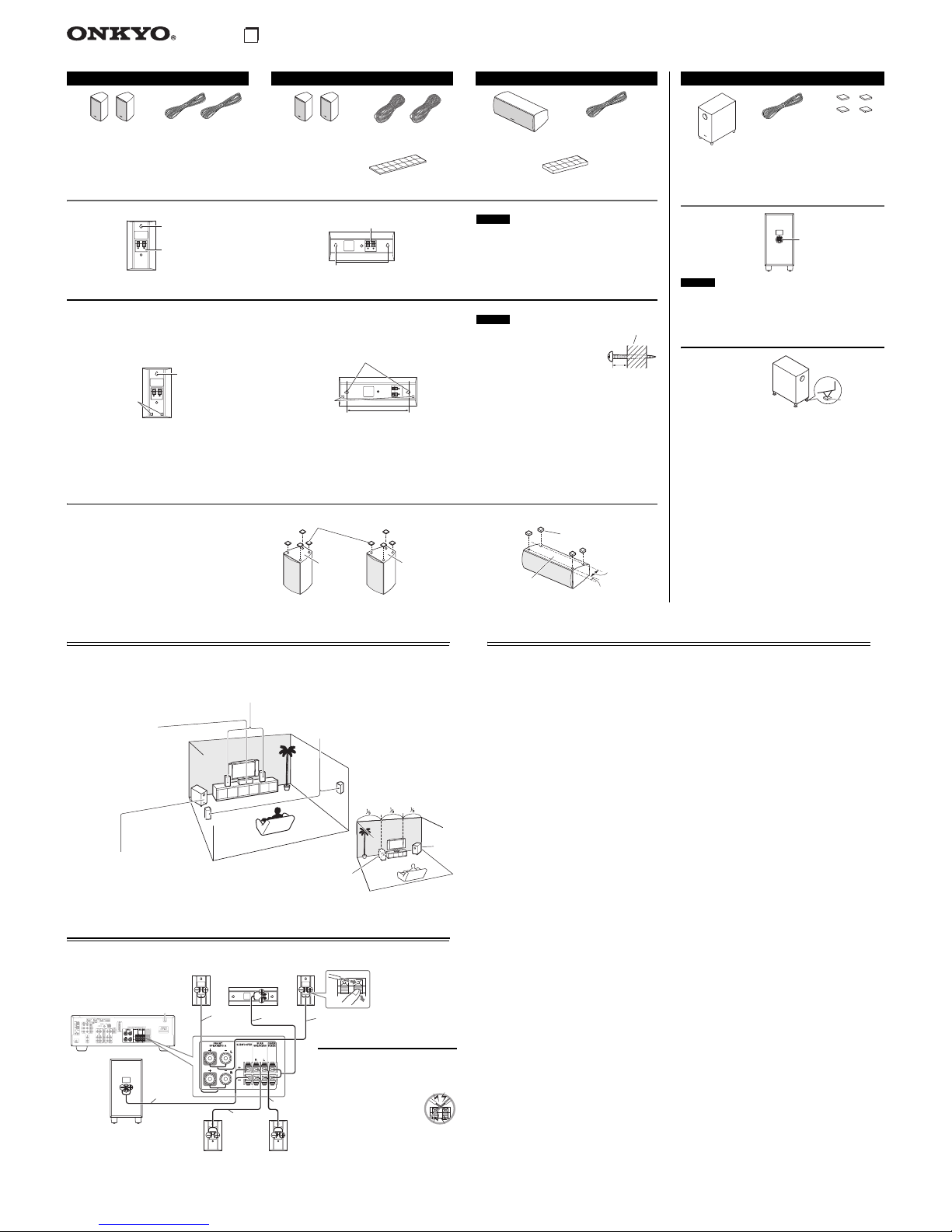
Anschließen der Lautsprecher
Eckposi
tion
1/3
Wandlänge
Center-Lautsprecher
(SKC-038)
Stellen Sie sie so nahe wie möglich
an den Fernseher (vorzugsweise
darauf) und richten Sie sie auf
Hörposition aus oder sie sie sollten
sich auf derselben Höhe befinden,
wie der linke und rechte Front-
Lautsprecher.
Linker und rechter Front-Lautsprecher (SKF-038)
Sie sollten auf die Hörer ausgerichtet sein, und zwar auf Ohrhöhe, und im gleich großen
Abstand zum Fernseher positioniert werden. Drehen Sie sie leicht nach innen, um ein
Dreieck zu erzielen, an dessen Unterseite sich der Hörer befindet.
Linker und rechter Surround-Lautsprecher
(SKR-038)
Sie sollten sich neben dem Hörer oder knapp
dahinter, etwa 60 bis 100 cm über Ohrhöhe
befinden. Idealerweise sollten Sie im gleichen
Abstand vom Zuhörer entfernt positioniert
werden.
Subwoofer (SKW-338)
Der Subwoofer gibt die Bass-Klänge des LFE-Kanals (Low-Frequency Effects)
wieder. Der Pegel und die Intensität der Basswiedergabe Ihres Subwoofers
sollte sich nach der Hörposition, der Form des Hörraums und seinem
Aufstellungsort richten. Im Allgemeinen kann ein guter Bassklang erzielt
werden, wenn man den Subwoofer in einer vorderen Ecke bzw. bei einem Drittel
der Länge der vorderen Wand gemäß der Abbildung aufstellt.
Rot Weiß
Blau
Grün
Front rechts
Lautsprecher Center-
Lautsprecher
Grau
Front links
Lautsprecher
Surround rechts
Lautsprecher
Surround links
Lautsprecher
Subwoofer
Vorsicht beim Anschließen der
Lautsprecher
Bevor Sie Ihre Lautsprecher anschließen,
lesen Sie sich folgende Hinweise durch:
• Schalten Sie Ihren Receiver aus, bevor Sie
Ihre Lautsprecher anschließen.
• Achten Sie dabei besonders auf
die Polarität der
Lautsprecherkabel. Verbinden
Sie den Pluspol (+) eines
Anschlusses mit dem Pluspol
(+) des Lautsprechers und den Minuspol (–)
eines Anschlusses mit dem Minuspol (–)
des Lautsprechers. Wenn Sie die Polarität
vertauschen, tritt eine Phasendrehung auf,
welche die Klangqualität beeinträchtigt.
• Vermeiden Sie außerdem Kurzschlüsse des
Plus- und Minuspols. Andernfalls könnte
Ihr Verstärker beschädigt werden.
Lila
Technische Daten
■Passiver Subwoofer (SKW-338)
■Front-Lautsprecher (SKF-038)
■Center-Lautsprecher (SKC-038)
■Surround-Lautsprecher (SKR-038)
Technische Daten und Aussehen können ohne vorherige
Ankündigung geändert werden.
Typ Bass-Reflex-Typ eines passiven
Subwoofers
Impedanz 6 Ω
Maximale Ausgangsleistung 130 W
Sensivität 82 dB/W/m
Frequenzverhalten 30 Hz bis 150 Hz
Gehäuse-Fassungsvermögen 24 L (0,8 Kubikfuß)
Abmessungen (B ×H ×T) 211 mm ×425 mm ×381 mm
(inkl. Überstand)
Gewicht 5,5 kg (12,1 lbs.)
Steuereinheit 16 cm Kegel ×1
Klemme Federzug farbkodiert
Typ Fullrange-Bassreflex
Eingangsempfindlichkeit/Impedanz
6 Ω
Maximale Eingangsleistung 120 W
Ausgangsschalldruckpegel 81 dB/W/m
Frequenzverhalten 80 Hz bis 20 kHz
Gehäuse-Fassungsvermögen 1,1 L (0,039 Kubikfuß)
Abmessungen (B ×H ×T) 101 mm × 175 mm × 116 mm
(inkl. Abdeckung und Überstand)
Gewicht 0,7 kg (1,54 lbs.)
Lautsprecher 8 cm Kegel ×1
Klemme Federzug farbkodiert
Befestigungsloch 1
Abdeckung Befestigt
Sonstige Magnetische Abschirmung
Typ Fullrange-Bassreflex
Eingangsempfindlichkeit/Impedanz
6 Ω
Maximale Eingangsleistung 120 W
Ausgangsschalldruckpegel 82 dB/W/m
Frequenzverhalten 80 Hz bis 20 kHz
Gehäuse-Fassungsvermögen 1,8 L (0,064 Kubikfuß)
Abmessungen (B ×H ×T) 237 mm ×101 mm ×106 mm
(inkl. Abdeckung und Überstand)
Gewicht 1,0 kg (2,2 lbs.)
Lautsprecher 8 cm Kegel ×1
Klemme Federzug farbkodiert
Befestigungsloch 2
Abdeckung Befestigt
Sonstige Magnetische Abschirmung
Typ Fullrange-Bassreflex
Eingangsempfindlichkeit/Impedanz
6 Ω
Maximale Eingangsleistung 120 W
Ausgangsschalldruckpegel 81 dB/W/m
Frequenzverhalten 80 Hz bis 20 kHz
Gehäuse-Fassungsvermögen 1,1 L (0,039 Kubikfuß)
Abmessungen (B ×H ×T) 101 mm ×175 mm ×116 mm
(inkl. Abdeckung und Überstand)
Gewicht 0,7 kg (1,54 lbs.)
Lautsprecher 8 cm Kegel ×1
Klemme Federzug farbkodiert
Befestigungsloch 1
Abdeckung Befestigt
*2 Nicht magnetische Abschirmung.
Achtung
• Die vorderen Abdeckungen können nicht entfernt werden.
Versuchen Sie daher nicht, sie gewaltsam zu entfernen. Sie
könnten beschädigt werden.
Verwendung der Bodenauflagen für den
Subwoofer
Wenn der Subwoofer auf
einem harten Boden (Holz,
Vinyl, Fliesen, usw.)
aufgestellt wird und das
Playback sehr laut ist,
können die Füße des
Subwoofers den Boden
beschädigen. Um dies zu vermeiden, platzieren Sie die gelieferten
Bodenauflagen unterhalb der Füße des Subwoofers. Die
Bodenauflagen bieten auch ein stabiles Fundament für den
Subwoofer.
Subwoofer (SKW-338)
Subwoofer*2
Lautsprecherkabel
3,0 m
4 Bodenauflagen
(Lila)
Lautsprecheranschlüsse
Bodenauflage
5.1ch Home Theater Speaker Package HTP-038
Wandmontage
Verwendung der Gummistopper für eine stabilere Plattform
Front-Lautsprecher (SKF-038) Surround-Lautsprecher (SKR-038) Center-Lautsprecher (SKC-038)
Front-Lautsprecher*1 Lautsprecherkabel 3,5 m Surround-Lautsprecher*2
Lautsprecherkabel 8,0 m Center-Lautsprecher*1
Lautsprecherkabel 3,0 m
*1 Zur magnetischen Abschirmung.
*2 Nicht magnetische Abschirmung.
*3 Die Konfiguration der Gummistopper kann von der Abbildung abweichen. So kann
es zum Beispiel 2 Blätter anstatt nur einem geben, aber die Gesamtzahl bleibt gleich. 16 dünne Gummistopper*3 12 dicke Gummistopper*3
Achtung
• Die vorderen Abdeckungen können nicht entfernt
werden. Versuchen Sie daher nicht, sie gewaltsam zu
entfernen. Sie könnten beschädigt werden.
Um die Front-/Surround-Lautsprecher vertikal zu
montieren, verwenden Sie das Befestigungsloch, um jeden
Lautsprecher an einer Schraube aufzuhängen, die sicher in
die Wand geschraubt wurde.
Um den Center-Lautsprecher horizontal zu montieren,
verwenden Sie die beiden Befestigungslöcher, um jeden
Lautsprecher an zwei Schrauben aufzuhängen, die sicher in
die Wand geschraubt wurden.
Achtung
• Die Tragfähigkeit einer
Befestigungsschraube hängt davon ab,
wie gut sie in der Wand verankert ist.
Wenn Sie Hohlwände haben, schrauben
Sie jede Befestigungsschraube in einen
Dübel. Wenn es keine Dübel gibt oder die
Wände stabil sind, verwenden Sie geeignete Wandanker.
Verwenden Sie Schrauben mit einem Kopfdurchmesser von
9 mm oder weniger und einem Kolbendurchmesser von 4 mm
oder weniger. Bei Hohlwänden verwenden Sie einen Kabel-/
Rohrleitungsdetektor, um die Wand nach Stromkabeln oder
Wasserleitungen abzusuchen, bevor Sie Löcher bohren.
• Lassen Sie eine Lücke zwischen 5 mm und 10 mm
zwischen der Wand und der Basis des Schraubenkopfes,
wie es gezeigt wird. (Wir empfehlen Ihnen, einen
Fachmann für die Installation bei Ihnen zu Hause zu
konsultieren.)
Wir empfehlen Ihnen die gelieferten Gummistopper zu
verwenden, um den bestmöglichen Klang mit Ihren
Lautsprechern zu erzielen. Die Gummistopper verhindern,
dass die Lautsprecher sich bewegen und bieten eine
stabilere Plattform. Verwenden Sie dicke Stopper für den
Center-Lautsprecher und dünne Stopper für die anderen
Lautsprecher.
(Weiß) (Rot) (Blau) (Grau)
(Grün)
Lautsprecheranschlüss
Befestigungsloch
SKF-038
SKR-038
Lautsprecheranschlüsse
Befestigungslöcher
SKC-038
Befestigungsloch
für Wandmontage
Dicke
Gummistopper
Befestigungslöcher für Wandmontage
217 mm
Dicke
Gummistopper
Wand
5 bis 10 mm
Dünne Gummistopper
Unterseite
der SKR-038
Unterseite
der SKF-038
Unterseite
der SKC-038
55 mm
12 mm
Dicke Gummistopper


 User manual")


