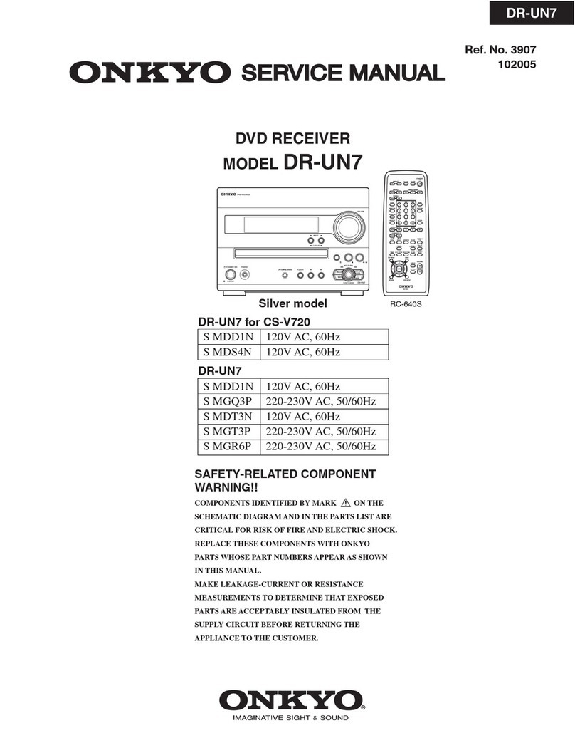
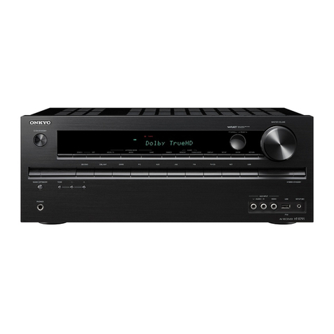
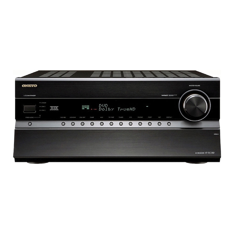
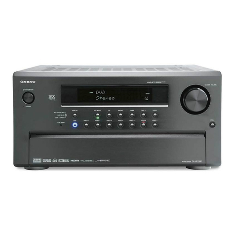
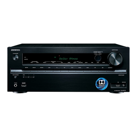
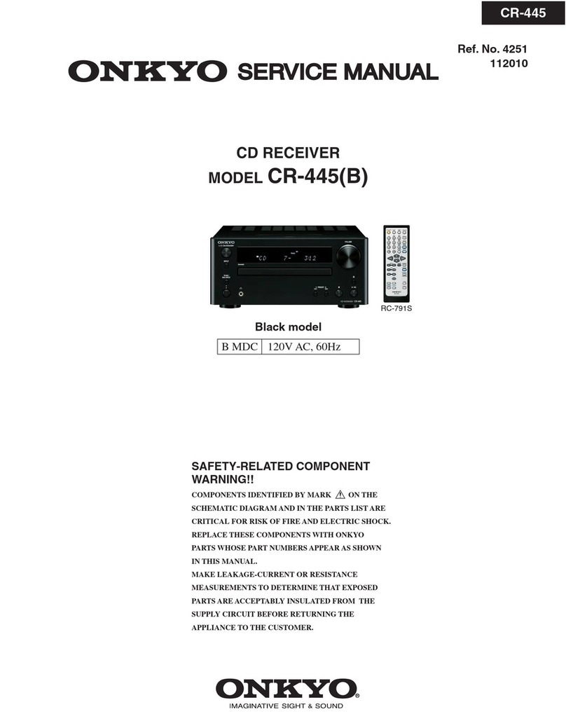
Onkyo CR-185 User manual

ONKYO.
SERVICE
MANUAL
COMPACT
DISC
RECEIVER
MODEL
CR-185
Black
and
Silver
models
|
UP
|
_230V_
AC,
50Hz
SAFETY-RELATED
COMPONENT
WARNING!!
TABLE
OF
CONTENTS
COMPONENTS
IDENTIFIED
BY
MARK
A\
ON
THE
Spemibcatiomn
elo
ei
eee
eal:
2
SCHEMATIC
DIAGRAM
AND
IN
THE
PARTS
LIST
ARE
CRITICAL
FOR
RISK
OF
FIRE
AND
ELECTRIC
SHOCK.
REPLACE
THESE
COMPONENTS
WITH
ONKYO
PARTS
;
WHOSE
PARTS
NUMBERS
APPEAR
AS
SHOWN
IN
THIS
Laser
waming
Dae
IS
oi
ss
csi
sscsseccts
echscesv
dacs
casdenvetidscdssevstecesacesss
MANUAL.
Microprocessor-connection
diagram....
ive
Caution
on
replacement
of
optical
pickup.
Protection
of
eyes
from
laser
Deam.........s.csssssssssesssosesenseerese
MAKE
LEAKAGE-CURRENT
OR
RESISTANCE
MEA-
SUREMENTS
TO
DETERMINE
THAT
EXPOSED
PARTS
ARE
ACCEPTABLY
INSULATED
FROM
THE
SUPPLY
CIRCUIT
BEFORE
RETURNING
THE
APPLIANCE
TO
THE
CUSTOMER.
Exploded
view
CD
adjustment
procedures
Tuner
adjustment
procedures..........s.csssssscscsssccssssosorsecnesnceseess
21
Service
procedures.
Pc
board
view from
soldering
side.
Schematic
diagram..............-sssscscsssccssssssssssecsesscnssacnceecesseceeeses
Pc
board
view
from
soldering
side.
F
Printed
circuit
board-parts
list............sescessccoressssesssseeneneseesees
Schematic
diagram
(Mechanism)............sccsssssssesseccocssnsseeees
34
N
K
Gr
Block
diagrams.
dei
aes
AUDIO
COMPONENTS
Packing
VieW..iccccesiscccccssteasescisscensasuouncceseusscstessseseanseues
stseeesees

CR-185
SPECIFICATIONS
AMP
SECTION
Power
Output:
Dynamic
Power:
Total
Harmonic
Distortion:
IM
Distortion:
Damping
Factor:
Sensitivity
and
Impedance:
Frequency
Response:
Tone
Control:
Single
to
Noise
Ratio:
Muting
General
Power
supply:
Dimensions:
Weight:
2
x
20
Watts
at
4
ohms
|
kHz
DIN
2x
17
Watts
at
6
ohms
1
kHz
DIN
2
x
15
Watts
at
8
ohms
1
kHz
DIN
2x
15
Watts
min
RMS
at
8
ohms
|
kHz
no
more
than
0.2
%
THD
2
x
24
Watts
at
4
ohms
2
x
18
Watts
at
8
ohms
0.2
%
at
Rated
Power
0.2
%
at
Rated
Power
40
at
8
ohms
TAPE
/
MD
PLAY
:
150
mV,
50
kohms
10
to
50,000
Hz
:
+0
/-3dB
Super
BASS
:
+
13
dB
at
55
Hz
BASS
:
+
10
dB
at
100
Hz
TREBLE
:
+
10
dB
at
10,000
Hz
TAPE
:
100
dB
(THF
A)
—co
dB
AC
230
volts,
50
Hz
185Wx
131Hx
329Dmm
(7-5/16"
x
5-3/16"
x
12-15/16")
4.0
kg
(8.8
Ibs)
Specifications
and
features
are
subject
to
change
without
notice.
FM
Tuner
section
Tuning
Range:
Usable
Sensitivity:
50
dB
Quieting:
Sensivity:
Capture
Ratio:
Image
Rejection
Ratio:
IF
Rejection
Ratio:
Signal
—
to
—
Noise:
Ratio
Selectivity:
Harmonic
Distortion:
Frequency
Response:
Stereo
Separation:
Stereo
Threshold:
CD
SECTION
Signal
readout
system:
Reading
rotation:
Linear
velocity:
Error
correction
system:
D/A
converter:
Digital
filter:
Number
of
channels:
Frequency
response:
87.50
to
108,00
MHz
(50
kHz
steps)
Mono
12.8
dBf,
1.2
pV
(75
ohms
IHF)
1.0
pV
(75
ohms
DIN)
Stereo
18.8
dBf,
2.2
pV
(75
ohms
IHF)
25.0
pV
(75
ohms
DIN)
Mono
18.8
dBf,
2.4
nV
(75
ohms)
Stereo
38.8
dBf,
24.0
pV
(75
ohms)
2.0
dB
85
dB
90
dB
Mono
73
dB,
IHF
Stereo
67
dB,
THF
50
dB
DIN
(+
/-
300
kHz
at
40
kHz
Devi.)
Mono
1.0
%
Stereo
1.5
%
30
to
15,000
Hz
(+/-
1.5
dB)
35
dB
at
1.000
Hz
25
dB
at
100
to
10,000
Hz
17.2
dBf,
2.0
pV
(75
ohms)
Optical
non-contact
About
500
—
200
r.p.m.
(constant
linear
velocity)
1.2-14m/s
Cross
Interleave
Read
Solomon
code
1
bit
352.8
kHz
8
times
over
sampling
2
(stereo)
5
Hz
-
20
kHz
CAUTION
ON
REPLACEMENT
OF
OPTICAL
PICKUP
During
repair,carefulley
take
the
following
precautions.
The
laser
diode
in
the
optical
pickup
block
is
so
sensitive
to
static
electricity
surge
current
and
etc,
that
the
components
are
liable
to
be
broken
down
or
its
reliability
remarkably
deteriorated.
PRECAUTIONS
1.Ground
for
the
work-desk.
Place
a
conductive
sheet
such
as
a
sheet
of
copper
(with
inpedance
lower
than
10M)
on
the
work-
desk
and
place
the
set
on
the
conductive
sheet
so
that
the
chassis.
2.Grounding
for
the
test
equipment
and
tools.
Test
equipments.
and
toolings
should
be
grounded
in
order
that
their
ground
level
is
the
same
the
ground
of
the
power
source.
(The
following
precautions
are
included
in
the
service
parts.)
,
3.Grounding
for
the
human
body.
Be
sure
to
put
on
a
wrist-strap
for
grounding
whose
other
end
is
grounded.
Be
particularly
careful
when
the
workers
wear
synthetic
fiber
clothes,
or
air
is
dry.
4.Select
a
soldering
iron
that
permits
no
leakage
and
have
the
tip
of
the
iron
well-grounded.
5.Do
not
check
the
laser
diode
terminals
with
the
probe
of
a
circuit
tester
or
oscilloscope.

CR-185
PROTECTION
OF
EYES
FROM
LASER
BEAM
DURING
SERVICING
This
set
employs
a
laser.
Therefore,
be
sure
to
follow
carefully
the
instructions
below
when
servicing.
WARNING!!
WHEN
SERVICING,
DO
NOT
APPROACH
THE
LASER
EXIT
WITH
THE
EYE
TOO
CLOSELY.
IN
CASE
IT
IS
NECESSARY
TO
CONFIRM
LASER
BEAM
EMMISION,
BE
SURE
TO
OBSERVE
FROM
A
DISTANCE
OF
MORE
THAN
30cm
FROM
THE
SURFACE
OF
THE
OBJECTIVE
LENS
ON
THE
OPTICAL
PICK-UP
BLOCK.
LASER
WARNING
LABELS
The
label!
shown
below
are
affixed.
1.
Warning
lable
This
label
is
located
on
the
chassis.
-
DANGER
INVISIBLE
LASER
RADIATION
WHEN
OPEN
AND
INTERLOCK
OR
TEE
Ae
REC
EXPOSURE
10
BEAM,
CAUTION
—sazaroous
Laser
AND
PLECTROMAGNETIC
RADIATION
WHEN
OPEN
AND
INTERLOCK
DEFEATED.
ENTION
_RAVONNEMENT
LASER
ET
ELECTROMAGNE
HQUE
DANGE
QUVERT
AVEC
L
ECLENCHEMENT
DE
SeCURITE
VARNING
OSYNLIG
LASERSTRALNING
NAR
DENNA
DEL
AR
OPPNAD
OCH
SPARREN
AR
URKOPPLAD.
BETRAKTA
EJ
STRALEN.
VARO!
ANATTAESSA
JA
SUOJALUKITUS
OHITETTAESSA
OLET
ALTTUNA
NAKYMATTOMALLE
LASERSATEILYLLE.
ALA
KATSO
SATEESEEN.
ADVARSEL:
USYNUG
LASERSTRALING
VED
ABNING,
NAR
SIKKERHEDSAF-
BRYDER
ER
UDE
AF
FUNKTION.
UNDGA
UDS/ETTELSE
FOR
STRALING.
®
:
Danger
label
©
:
Only
230V
model
ADVARSEL
{USYNLIG
LASERSTRALING
NAR
DEKSEL
APNES
OG
SIKKERHEDSLAS
BRYTES.
UNNGA
EKSPONERING
FOR
STRALEN.
Laser
Diode
Properties
@
Material:
GaAlAs
@
Wavelength:
760
~
800
nm
@
Emission
Duration:
continuous
@
Laser
output:
max.
0.5mW*
*This
output
is
the
value
measured
at
a
distance
about
1.8mm
from
the
objective
lens
surface
on
the
Optical
Pick-up
Block.
2.
Class
I
label
This
label
is
located
on
the
left
side
of
top
cover.
LUOKAN
1
“CLASS
1
LASER
LASERLAITE
PRODUCT”
KLASS
1
LASER
APPARAT
ADVARSEL
Denna
maekning
er
anbragt
pd
apparatets
hojre
side
og
ind
ikerer,
at
apparatet
arbejder
med
jaserstraler
af
klasse
1,
hvilket
betyder,
at
der
anvendes
laserstraler
af
svageste
klasse,
og
at
man
ikke
pa
apparatets
yderside
kan
blive
udsat
for
utilladelig
kraf
tig
straling.
APPARATET
BQ@/R
KUN
ABNES
AF
FAGFOLK
MED
SE
RLIGT
KENDSKAB
TIL
APPARATER
MED
LASERSTRALER!
Indvendigt
i
apparatet
er
anbragt
den
her
gengivne
advarselsmérkning,
som
advarer
imod
at
foretage
sadnne
isdgreb
i
apparatet,
at
man
kan
komme
til
at
udsaette
sig
for
lasers
raling.
VAROITUS!
LAITTEEN
KAYTTAMINEN
MUULLA
KUIN
TASSA
KAYTTOOHJEESSA
MAINTULLA
TAVALLA
SAATTAA
ALTISTAA
KAYTTAJAN
TURVALLISUUSLY
OKAN
1
YLITTAVALLE
NAKYMATTOMALLE
LASERSATEILYELE.

CR-185
MICROPROCESSOR
CONNECTION
DIAGRAM
uPD78044AGF-123
Q30!
SIGNAL
PROCESSOR
Ve
Q703
SYSTEM
R T
-
2
*
5
i
°
z
c
CDDATA
| |
!
1
1
=
o
OPERATION
27
|
ve,
|
|
wey
[26]
a
ee
ee
+5y
22
|
zw
|
owen
+5v
22
Ys.
|]
STOPPAGE
Bt
pial
74»
|_|
DETECTOR
>
32
»
PD78044AGF
pst
23»
_| _|
a
=
a
INPUT
SELECTOR
oy
v2
|
4.19MHz
X'TA
7
osc
|
3s
|
70
36
|
«os
|
w
Pp
le
||
2
Ciiaratal
meaner
ee
ee
Qi131
PUL
SYNTHESIZER
AND
CONTROLLE
P
BUZZER
LM700)1
@|
[outs]
se
|
Q
&
Q591.0592
AMP.
+8
sw
ast
RDS
DECOODER
PC134.0cS
4
xe
aS
RI
O
=o
ey
(N/OU
Fe
FO
on
|
Operation
|
VOLUP
output]
VOLDOWN
output
ae
ae
a
|
vorup
[|
ow
|
VOL
DOWN
1
Barheie
=
-.
>|
87.50~
108MHz
Worldwide
_|87.50~
108MHz
Table
1
1
87.9~
107.9MHz
Japan
Table
2
Table
3
FTO

TERMINAL
DESCRIPTIONS
Function
4G710G
CDDATA
SQCK
Sense
signal
input
terminal.
Connect
the
terminal
SENS
of
signal
processor
IC.
STEREO
AVSS
VOL
UP
Refer
the
table
1.
SBASS
Super
bass
control
output
terminal.
Pin
No.
17
<
o
—]
_
oy
~
~
wi
1
14
3
_
ZEB
REGAL
ihistall
—
n
_
\o
20
21
22
23
24
Initializing
setting
terminal
for
the
Frequency
range.
25
IN/OUT
Input
terminal
for
tray
open/close
detection switches.
26
SIGNAL
Signal
level
input
terminal
for
automatic
memory.
Operation
key
connection
terminals
AVDD
Analog
power
supply
for
D/A
converter.
g
~
29
30
AVREF
Reference
power
supply
for
D/A
converter.
fill
il
Crystal
resonator
connection
terminal
for
sub
system.
SS
<
We
[2
fod TWO
vu
Wd
[=
oo
>
Ceramic
resonator
connection
terminal
for
main
system.
Connect
the
4.19MHz
ceramic
resonator.
Clock
output
terminal
for
PLL
IC
and
the
source
selector
IC.
RDS
broadcast
detection
terminal.
Sub
code
detection
terminal.
Connect
the
terminal
SCOR
of
signal
processor
IC.
Ww
wa
36
37
38
39
40
41
42
>
w
BISI5
(Z(EIZ
SIZE
OjAlla
|B
TI
IS
IN
Ic
~—
RIAN
21a
|S
~
Ol>
1S
|"
7
|>
>\s
Ww
44
45
46
Clock
input
terminal
from
RDS
decoder.
nx
&
|B
216
nw
System
code
output
terminal.
>
~“_
49
50
EP
>
QA
SER)
z
9
5
Gis
z
sla
Power
supply
terminal
for
CD
mechanism
Defect
output
pin
for
CD
mechanism.
aw~wIa
zal
4|z
ies!
~]
bel
E
SE
Optical
pickup
control
output
terminal.
Pu
OAD
ewes
eniompdaeta
ee
z
51
52
33
34
355
56
s7
58
59
iit
ia]
nN
i
Zz
a

CR-185
IC
BLOCK
DIAGRAM
AND
DESCRIPTIONS
CXA1372Q
(Servo
Signal
Processor)
WOiVuvdWO?
MOONIM
[
asa]
3
g
»
=
¥
2
v
a
>
a
wv
~
a
z
2-103
4200330
inaiNo
8300320
«=SSauddv
PEPtIpEl
|
ONIMIV
ML
€-1Sd
2-1
AdIHS
INN
NOILVSNIdGWOD
3S
Ord
[PIN
NO.
SYMBOL
|V/O
[DESCIRPION
[PINNO.
[SYMBOL
[VO
[DESCIRPION,
}
VC
TT
|
Mid-point
voltage
input
terminal.
[|
23(XLT___|_1
[Latch
input
terminal
for
microprocessor.
|
Connect
the
capacitor
between
FS3andthispin
|
_24{DATA
__|
I
[Serial
data
input
terminal
for
microprocessor.
__|
2
when
the
high
frequency
gain
focus
servo
[____2S|XRST__|
1
[Resetinputterminal.Activelow.
is
dropped.
|
___26{C.0UT___|
©
[Signal
ourput
to
count
the
track
numbers.
i
ecient
all
Ee
input
terminal.
according
command
from
the
microprocessor.
FLB
Input
terminal
for
the
low
frequency
boost
of
[__29[MIRR___|
O
[Mirrorcomparator
outputterminal.
pe
Neeser.
aber
To
leted
eomemrens
usec
eran
FEO
9
Focus
drive
ourput
terminal.
|
3K{ASY
_[_{
[Auto
asymmenry
conwol
input
terminal.
|
____«|FE-
|_1
[Inversion
input
terminal
of
focus
amplifier.
[__32{EFM___'|
O
[EFMcomparator
output
terminal.
|
Lee
fee
als
algae
Pe
a
es
select
=|
ore
beam
ine
eee
ee
waveform.
|
34{CCi_
0
[Defect
boom
hold
outputterminal.
eee
terminal.
37|CB__[_T_
[Defect
bottom
hold
capacitor
connection
terminal,
_|
|
1i[TAO
|
O
[Tracking
drive
outputterminal.
S|
~SSBICP
ss
[Mirror
hold
capacitor
connection
terminal.
|
|
14|SLO
[0
{Sied
drive
ourputterminal
|S
AQTZC
OT
|
Tracking
zero-cross
comparator
input
terminal.
|
|
__t5|St-___|
_I_
|
Inversion
input
terminal
of
sled
amplifier.
[43/TE
ss
[Tracking
errorinputterminal,
Sees
ener
ee
focus
tracking.
when
defect.
This
terminal
is
flowed
the
current
so
that
the
ee
ae
Window
comparator
input
terminal
for
ATSC
7
focus
search,tarcking
jump,and
sled
kick
height
detection.
is
decided.
{
—-461FZC
—si|_1._
[Focos
zero-cross
comparator
input
terminal.
[——TaISSTOP
1
[inner
swich
sclection
input
emia,
|
47]FE
[1
Focus
error
input
terminal,
|_____20(DIRC
__|[_I_
[This
terminal
is
used
when
track
jump.
4
FDFCT
aa
Capacitor
connection
terminal
for
time
constant
ae
The
sted
runaway
prevention
circuit
operates
when
defect.
at
the
low
level.
i
eae
G2
Serial
data
transfer
clock
input
from
microprocessor.

CR-185
SM5875BM
(DA
CONVERTER)
LRCI
DI
(8)
(6)
INPUT
INTERFACE
FILTER
ARITHMETIC
AND
ATTENUATION
ARITHMETIC
ATTENUATION
MUTE
COUNTER
MODE
@3)
RSTN
3)
|
conn:
ne
D
CONTROL
(i9)
XTO
pvss
@)
PWM
DATA
NOISE
SHAVER
GENERATION
ARITHMETIC
xTI
vi
pvop
©
BLOCK
BLOCK
TSTN
(9)
G7)
XVDD
TO1
TO2
AVDDL
(11)
AVDDR
LO
AVSS
RO
MODE=H:Muting
control
pin
70
De-emphasis
control
pin.
On
at
high
level.
MODE=L:
Attenuator
level
control
pin
Analogue
supply
pin
for
left
channel
Clock
output
pin:
16.9344MHz
Analogue
signal
output
pin
for
left
channel
Test
output
terminal
Supply
pin
for
resonator
system
Crystal
connection
or
external
clock
input
pin
Crystal
connection
pin
Supply
pin
for
resonator
system
Playback
speed
select
pin.
Double
speed
at
H

CXD2500A/BQ
(Digital
Signal
Processor)
9
DAO!~I6
9
MUTE

CR-185
[no.
|syMBoL
|yo[pescrrrion
ss
CC™—~—~—~CSCSC*dS_NO._
|
SyMBO_|
YO
DESCRIPTION
1
Irok
|
1
|roucsOkinpt
SS
SS™S™~—~sSCS
Ea
sO
|
[DAOS
—GESoupr
|
2
[rsw
|
©
[Output
filter
changeover
output
for
spindle
motor
||
43
|DAO7
|
O
[DAG7
_—IRFCKoupu.
3
[MON
|
[Spindle
motor
control
ouput
Cid
|
44
AOS
|
©
[DADS
—*[C2POoupu
Cd
4
|Mpp
|
0
[Spindle
motor
servoconrol
Sd)
|
45
—IDAOS
|
O
[DAOS
—|XRAOFoupu
Ts
Imps
|
©
[Spindle
motor
servocomrot
Ss
|
46
(DADS
«|
[DAOA
—|MNTSoutp
|
6
|tock
|
O
|HwhenGrSisthehighievel
«|
|
47
_‘[a03
|
[DAO3
[MNT
2ompur
[7
Inc
|
|.
T™t™~™~—.
CC~C*~*~*SYCSYT=SC48
a
~—s
fc
DAD
—MNTiompuw
|
|vcoo
__|
©
|Oscillation
circuit
output
for
analog
EFM
PLL.
[49
|Daor
|
O
[paot
_—s[MNTOoupm
ike
i
eeereet
ie
eter
[50_[APTR
|
©
|Controt
output
for
aperture
correction.
H
when
R
ch._|
(8.6436MHz
[51
{APTL
|
©
[Control
output
for
aperture
correction.
H
when
L
ch._|
to
frest
[1
[Testemint
—SSSS—™—~—CSsS—SS—S
|S
vss
|
Grounderminds
SC
—E
T2
[vss
|
[Grounduermind
33.8688MHz
input.
risisinc.
|
|
—™—SC~C~CS
84
Fx
[0
[crystal
oscillation
circuit
output
of
16.9344MH2.
|
|
46
|VPCO
_|
O
[PLU
charge
pump
output
for
variable
pitch
eal
cee
Go
selection
input
terminal.
L
when
16.9344MHz.
ee
ae
Clock
input
for
variable
pitch
from
VCO
H
when
33.8688MHz.
16.934MHz
[36
_[estr___|
©
2/3
divided
ouputof
pins
53
and54.
Yas
[ro
|
©
|FikerourputformasterPLL.
Sd
|_S7_
CAM
To
[4.2336MHzoup
19
Temi
1
1
[rimer
input
for
master
PLL.
SSSS~s«_
88
|cugM
[0
fi6.9344MHzoupm
=
|
20
Ipco
_|_©
|charge
pump
output
of
master
PLL
1
~s9
[mp2
sr
|
Digital
oui
pat
contro!
input.
On
at
high
level.
|
21
|AVss
|__|
Analog
ground
60
_|pout
|
©
[Digiatoupn
.
2
{erty
__|_1
[vcO
contol
voltage
input
for
master
[61
|EMPH
|
O
[Emphasis
conwol
ouput.
Active
high,
|
|
23,
[AVDD
|__|
Analog
section
power
supply
(+5
|
62_|weck
|
0
|Writeframeclock
outpt
ee
ale
aaa
95
|BIAS
|
1
{A
mmety
circuit
constant
current
input
or
SI.
|
9%
lasyr
|
1
[a
mmetry
comp
or
voltage
input
|
64_|sBSO_|
©
|Serial
ourputof
subcode(P~W)
T_27
lasyo
|
O
\EFMfullswingouput
|
65
|EXCK
|
1
|Ctock
inputforreadouSQso.
Pte
ecm
[Foes
ae
ree
el
ee
eee
output.
Pee
Audio
data
output
mode
changeover
input
|
_67_|sgcx
|
1
|ClockinputforreadoutSQsO_
Serial
data
at
L
and
paraller
data
at
H.
[68
[MUTE
|
©
[Mutingconwrol
ouput.
ActiveH.
Par
[wack
__|_1
JD/A
interface
for
48
bits
slot.
Word
clock
f=2Fs.
|
|_69
[SENS
|
[Sens
ourput.
Output
to
the
microprocessor
|
Y
32
|URCK
|
_1
[D/A
imestace
for
48
bits
slot.
LR
clock
f=Fs._|
70
_|xRsT
__|
1
|System
reset.
Resetatthelow
level.
T~33
Ivpp
___|__frower
supply
terminal
(+5V)
«|
|_71
[DATA
|
_1
[Serial
data
input
from
the
microprocessor.
|
as
Dal
al
=n
YT
|S
C=*d:SsédP
sum
[pssu-o
Latch
the
serial
data
at
the
wailing.
|
34
[pais
_|
O
|DAt6
[73
|vpp
|
[Powersupply
remind
[35
(DAIS
|
O
DAIS
_[Bitclockof
48
bits
slor__|
|
74
[cox
|
1
|Serial
data
transfer
clock
input
from
microprocessor_|
|
36
[DAis
|
O
|DA14
__|Serial
data
of
64
bits
slot_|
[75
[sein
|
1
|SensinputfromSsP_
DAI3
TO
|DAI3
_[Bitclock
of
68
bits
slot__|
CNCI
1
[Track
jump
numbers
count
signal
input_
|
|
38
|DAI2
|
O
|DAI2
_
LR
clock
of
68
bits
slon__
|
77_[DATO
|
0
|SerialdataoupmoSSP_
[39
{pai
|
O
[DAN
—(GTOPowpur
[78
|xtTO
|
©
[Serial
data
latch
output
to
SSP.
Latch
at
wailing.
_|
[4
|paio
|
Oo
|DaAio
—|xUGFoupu
[79
[ctKo
|
0
|Serial
datawansferclock
ouput
to
SSP.
|
41
|DAo9
|o
[paog
_|XPLCK
output
[80
_[MIRR
|
1
[Mirorsignalinpr
Note:
SSP:
1C101
CXA1372Q

CR-185
BA1448S
(AM
Radio,
FM
IF,
and
Stereo
System)
[No.
|
Terminal
Descriptions
[1
[EM
IFamplifierinputterminal
|
13
Groundterminl
|
16
[FM/AM
detectorsignal
output
terminal
|
=
=
Terminal
Descriptions
|
a
|
[7
stereo
indicator
terminal
|
19
[AMmixer
outputterminal
|
[8
[tFrequest
and
Muting
terminal
|
20
[AMamtennatermingl
[9
|iFsignaltermin
|
[11
[Leftchannel
output
terminal
|
23
(Reference
voltage
terminal
AM
local
oscillator
output
terminal
LM7001
(PLL
Synthesizer
and
Controller)
aé.
Tuning
indicator
terminal
18
|
AM
FF
input
terminal
10
AMIN
'
j

CR-185
XOUT
Connect
the
7.2MHz
crystal
resonator.
7
lupe
[upFsetectoroup,
[ANT
[Antenna
selector
output.
A
athigh
evel
andBatlowlevek
|
SAT/
E
LPF
FM
local
oscillator
input
terminal.
Power
source
terminal
for
back-up.
VDD2
Power
source
terminal.
Phase
comparator
output
15
Phase
comparator
output
4
12
13
Ground
terminal
uPC1346CS
(RDS
DECODER)
BIPHASE
DECODER
DEF.
Description Description
Supply
voltage
for the
digital
circuit
Ground
for
the
analog
circuit
Resonator
input
|
ia
|intec
_|
Integrating
filter
terminal
Adjustment
fc
of
band
pass
filter
Ground
for
the
digital
circuit
Biphase
signal
output
Test
input
te
|
19
|
Zz
¢
:
Resonator
output
Qa
10
1O
I<
B
ip
le
(2
[2
|
TERED
Zk
IS
Id
4
i
PER
e)
:
SOUT
OCK
OUT
ATA
OUT
as,
i
12
oO

LEVEL
SHIFTER
i
a,
a
LATCH
CIRCUIT
LATCH
CIRCUIT
TC9184P
(Electro
Tone
Volume)
TREBLE
+
TREBLE
-
COM
BASS
-
BASS
+
Function
|
No.
|Symbo!__
Fs
ocean
|
16
|vpp__|
Volume
terminals
BASS
-
(Ground
terminal
for
digital
section
‘Clock
input
terminal
to
take
in
the
data
of
terminal
DATA.
~12—
Peet
‘
a

CR-185
TA7291
(VOLUME
MOTOR
DRIVER)
Vcc
Vref
ourpur
{|
Cw/CCWw
CCw/CW
BRAKE
CCW:Counter
clockwise
direction
CW:Clockwise
direction
INI
=
IN2
GND
REMOVEMENT
OF
TRAY
ASS’Y
Remove
the
top
cover.
Turn
the
locked
screw
to
the
clockwise
to
release
the
lock
of
gear.(Refer
fig.
1)
Pull
out
the
tray
ass'y.
Remove
the
stopper.(Refer
fig.2)
Press
the
tray
stopper
to
the
arrow
mark
direction
and
remove
the
tray
ass'y.
UNLOCK
~
ie
iO
Front
Panel
Clear
Plate
fig.
1
—~13—

CR-185
MECHANISM-EXPLODED
VIEW
—14—

102
10}
4)
PARTS
LIST
REF.NO.
PART
NO.
1
24840053
3
24822014
4
24810020
5
24840061
7
24830003
8
24832004
9
24836013
10
24810024
11
24802012
12
24820023
15
24840075
17
24802013
19
24810021
20
24840063
21
24840064
107
{
Ch)
:
©
RI2
Pe
Sey
ARs
[Ud
DESCRIPTION
Tray
Gear
cover
Tray
gear
Chucking
plate
Chucking
yoke
Magnet
Damper
Chucking
plate
Sub-chassis
Spring
CD
servo
pcb
ass'y
Main
chassis
Drive
gear
Control
cam
Leafswitch
—15—
102
110
REF.NO.
PART
NO.
22
25055369
23
24840066
24
24840067
25
24810022
26
24810025
27
248
16008
101
24828006
102
=.
24836014
104
=.
24822015
105
24820024
106
24824003
107
24110011
108
24810023
109
24802014
110
24804012
CR-185
108
DESCRIPTION
NPLG-5P352,Plug
Loading
motor
pe
bourd
Loading
motor
Middle
gear
Loading
plate
Belt
Sled
shaft
S
Insulator
S
Plate
S
Spring
Center
ring
KSS-240A,
Optical
pckusp
Wheel
Chassis
Motor
gear

CR-185
PARTS
LIST
REF.NO.
PART
NO.
DESCRIPTION
REF.NO.
PART
NO.
DESCRIPTION
1
27110865
Front
bracket
<B>
F901
252063
A\
0.5A-SE-EAWK,
Primary
fuse
ae
27110866
Front
bracket
<S>
P301
2046223012
NCFC6-223012,
Flat
cable
%
3
27100296
Chassis
P701
2047350512
NCFC7-350512,
Flat
cable
7
5
27122062
Rear
panel
P901
253193HIT
_A\
AS-CEE,
Power
supply
cord
7
28184583
Cover,
mechanism
Q557,Q558
2202063,
28C4511-0,
9
27160350
Radiator
2202064
or
2SC4511-Y
or
10
28184584
Cover,
radiator
2202066
2SC4511-P,
Transistor
11
27300750
A\
#2271,
Cord
bushing
Q559,Q560
2202053,
2SA1725-0,
15
838130088
3TTB+8B,
Self-tapping
screw
2202054
or
2SA1725-Y
or
16
870065
Washer
PT
2202056
2SA1725-P,
Transistor
-
17
830440089
4TTC+8C(BC),
Self-tapping
screw
T901
2301108
or
A
NPT-1241P
or
18
801433
3SMS8W.SW+14B(BC),
Sems
screw
2301125
A
NPT-1241P,
Power
transformer
19
838130088
3TTB+8B,
Self-tapping
screw
Ul
1H266558-2
NAAF-5458-2,
Preamplifier
circuit
pc
board
ass'y
26
28175213
Isolating
plate
U2
1H266559-2
NAPS-5459-2,
Power
supply
circuit
pc
board
ass'y
27
27301815
-
Cover
F
U3
1H266560-2
NADIS-5460-2,
Display
circuit
pc
board
ass'y
31
28184585
Top
cover
<B>
U4
1H266562-2
NAAR-5462-2,
Tuner
circuit
pc
board
ass'y
28184586
Top
cover
<S>
U5
1H266563-2
NAAF-5463-2,
Main
amplifier
circuit
pe
board
ass'y
32
838430088
3TTB+8B(BC),
Self-tapping
screw
<B>
U6
1H266564-2
NAETC-5464-2,
Speaker
terminal
pc
board
ass'y
a
834230088
3TTS+8B(Ni),
Nickel
screw
<S>
Zl
24800009C
NCD-130S,
CD
mechanism
ass'y
.
37
28141264
t5*80*15,
Cushion
7
51
27211710
Front
panel
<B>
NOTE:
<B>:
Black
model
only
27211711
Front
panel
<S>
<S>:
Silver
model
only
52
801230
3TTS+8B(BC),
Self-tapping
screw
53
28135241Y
Badge
54
28133311
Back
plate
<B>
28133260
Back
plate
<S>
55
28191711
Clear
plate
NOTE:
THE
COMPONENTS
IDENTIFIED
BY
MARK
A
ARE
56
28191712
Clear
plate
RE
CRITICAL
FOR
RISK
OF
FIRE
AND
ELECTRIC
SHOCK.
58
28148307
Door
<B>
REPLACE
ONLY
WITH
PART
NUMBER
SPECIFIED.
f
28148308
Door
<S>
a
61
27175252-1BY
Leg
62
838130088
3TTB+8B,
Self-tapping
screw
64
29360687
Label
CLASS
1
65
29361862
Rating
label
81
28325130
Knob,
volume
<B>
28325131
Knob,
volume
<S>
91
260208
Wire
tie
92
29361731A
Label
93
834130087
3TTS+8S,
Self-tapping
screw
a
46

CR-185
\
u
Ny
eon
Ni
8
Ly
:
PK
iyi;
A
NN
{}
/,
0
7
ma)
5
A
>)
3
(
ay
Wr
f
ANY
=
0
iL&
G
/
f
/
/
0
f
/
\
/
EXPLODED
VIEW
oN
—~18—
—17—
V16571
/
Druck
1

ADJUSTMENT
PROCEDURES
It
is
not
necessary
to
perform
the
adjustment
of
optical
pickup.
This
confirmation
should
be
made when
replacing
the
optical
pickup.
1).
Connect
the
oscilloscope
to
test
points
RF
and
VC.
Osilloscope
DC
range
RF/Servo
pc
board
TPF)
G
TP(VC)
G
2).
Turn
the
power
switch
on.
3).
Load
the
test
disc
YEDS-18
on
the
tray
and
press
the
play
button.
4).
Confirm
that
the
waveform
on
the
oscilloscope
is
optimum
eye
_
pattern
and
optimum
level
as
shown
photo
1.
Optimum
eye
pattern
means
that
shape
"©"
can
be
clearly
distinguished
at
the
center
of
the
waveform.
RF
signal
waveform
CH
P1i36.2e4
A
.Syps
CH1
445
.Sihz
CH
S@uU
cxasSGal
A=1.2V
+
0.2
(Vp-p)
—~19—
V16571
/
Druck
2
Focus/Tracking
Gain
Adjustment
A
frequency
response
analyzer
is
necessary
in
order
to
perform
this
adjustment
exactly.
However,
this
gain
has
a
margin,
so
even
if
it
is
slightly
off,
there
is
no
problem.
Therefore,
do
not
perform
this
adjustment.
_Focus/tracking
gain
determines
the
pick-up
follow-
up
(vertical
and
horizontal)
relative
to
mechanical
noise
and
mechanical
shock
when
the
2-axis
device
operate.
However,
as
these
reciprocate,
the
adjustment
is
at
the
point
where
both
are
satisfied.
@
When
gain
is
raised,
the
noise
when
the
2-axis
device
operates
increases.
When
gain
is
lowered,
it
is
more
susceptible
to
mechanical
shock
and
skipping
occurs
more
easily.
When
gain
adjustment
is
off,
the
symptoms
below
appear.
e
The
time
until
music
starts
becomes
longer
for
STOP
+
DPLAY
or
automatic
Selection
(Ke@
PPE
buttons
pressed.
(Normally
takes
about
2
seconds.)
e
Music
does
not
start
and
disc
continues
to
rotate
for
STOP
—>DPLAY
or
automatic
selection
(Ked
bt
buttons
pressed.)
e
Sound
is
interrupted
dur-
ing
PLAY.
Or
time
count-
er
display
stops
progress-
ing.
e
More
poise
during
2-axis
device
operation.
The
following
is
a
simple
adjustment
method.
~
Simple
Adjustment
—
Note:
Since
exact
adjustment
cannot
be
performed,
remem-
ber
the
positions
of
the
controls
before
performing
the
adjustment.
If
the
positions
after
the
simple
adjust-
ment-are
only
a
little
different,
return
the
controls
to
the
original
position.
oscilloscope
(OC
range)
Procedure:
Main
board
&
TP
(FEO)
a
ey
+
!
ck
TP
(VC)
|
TP
(TEO)
Om-
-?
.
Keep
the
set
horizontal.
If
the
set
is
not
horizontal,
this
adjustment
[sao
be
performed
due
to
the
gravity
against
the
2
axis
device.
.
Insert
disc
(YEDS-18)
and
press
>
PLAY
button.
.
Connect
oscilloscope
to
RF/
Servo
board
TP
(FE).
.
Adjust
RV102
so
that
the
waveform
is
as
shown
in
the
figure
below.
(focus
gain
adjustment)
VOLT/DIV:
100mv
TIME/OIV:
2mS
100
mv
Ov
@
Incorrent
Examples
(DC
level
changes
more
than
on
adjusted
waveform)
low
focus
gain
VOLT/DIV:
100mv
TIME/DIV:
2mS
high
focus
gain
VOLT/ODIV.
100
TIME/DIV:
2mS
5.
Connect
oscilloscope
to
RF/
Servo
board
TP
(TE).
6.
Adjust
RV101
so
that
the
waveform
is
as
shown
in
the
figure
below.
(tracking
gain
adjustment)
VOLT/OIlV:
IV
TIME/OIV:
2mS
@
Incorrect
Examples
(fundamental
wave
appears)
low
tracking
gain
VOLT/OIlV:
IV
TIME/OIV:
2mS
high
tracking
gain
(higher
fundamental
wave
than
for
low
gain)
VOLT/OIv:
1V
TIME/OIV:
2mS
nA
Ae
A
fw
Ahab
med
b
dy
y
Vv
verti
Adjustment
Location:
RF/
Servo
board

V16571
/
Druck
3
ADJUSTMENT
PROCEDURES
Preparation
1.
Input
FM
mono:
1kHz,
75kHz
devi.,
60dB/
2
V
FM
stereo:
1kHz,
67.5kHz
devi.,
60dB/
V
Pilot
signal
19kHz
7.5kHz
devi.
2.
Outputs
Connect
the
non-inductive
type
resistor
of
8
ohms
to
the
all
speaker
terminals
unless
otherwise
noted.
FM
ADJUSTMENT
Connection
FM
SG
Stereo
modu-|
Tuning
of
instrument
output
lator
output
|
frequency
99.0MHz
1kHz
75kHz
devi.
AC
voltmeter]
TF?
on
the
65dBf(60dB)
atcod
99.0MHz
:
i :
Signal
Muting
‘
99.0MHz
|
Oscillosco;
AC
voltmeter
Generator
Oscilloscope
FM
MUTE/MODE
switch:
MONO
FM
MUTE/MODE
switch:
AUTO
Output
or
Oscillo-
Generator
scope
<Fig.
2>
RDS
decoder
J
.
*
Signal
Oscilloscope
AF
oscillator
Generator
—-21—
Output
Adjustment
Adjust
indicator
point
for
CR-185
SERVICE
PROCEDURES
1.
Replacing
the
fuses
3.
Safety-check
out
After
correcting
the
original
service
problem,
perform
the
i
[Tt
This
symbol
located
near
the
fuse
indicates
that
the
following
safety
check
before
releasing
the
set
to
the
customer.
fuse
used
is
fast
operating
type.
For
continued
protection
against
Connect
the
insulating-resistance
tester
between
the
plug
of
power
supply
cord
and
the
screw
on
the
back
panel.
Specifications:
More
than
10
MQ
at
500V.
fire
hazard,
replace
with
same
type
fuse.
For
fuse
rating
refer
to
the
marking
adjacent
to
the
symbol.
=
=a
Ce
symbole
indique
que
le
fusible
utlise
est
a
rapide.
Pour
une
protection
permanente,
n'utiliser
que
des
fusibles
de
4.
Memory
preservation
meme
type.
Ce
darnier
est
indique
la
qu
le
present
symbol
est
This
unit
does
not
require
memory
preservation
batteries.
appose.
A
built-in
memory
power
back-up
system
preserves
contents
of
the
memory
during
power
failures
and
even
when
the
unit
is
CIRCUIT
NO.
PART
NO.
DESCRIPTION
unplugged.
F901
252063
0.5A-SE-EAK,
Primary
The
unit
must
be
plugged
in
and
the
power
switch
turned
on
and
off
once
in
order
to
charge
the
back-up
system.
Note
that
since
this
is
not
a
permanent
memory,
the
power
switch
must
be
t
2.
To
Initialize
the
unit
pe
ry
po
umned
This
device
employs
a
microprocessor
to
perform
various
functions
and
operations.
If
interference
generated
by
an
external.
on
and
off
a
few
times
each
month
the
keep
the
back-up
system
operative.
The
period
of
the
time
during
which
memory
contents
are
power
supply,
radio
wave,
or
other
electrical
source
results
in
. ‘
preserved
after
power
has
last
been
turned
off
varies
depending
accident
which
causes
the
specified
operations
and
functions
to
:
;
on
climate
and
placement
of
the
unit.
On
the
average,
memory
operate
abnormally.
dj
f
contents
are
protected
over
a
period
of
3
to
4
weeks
(a
minimum
To
perform
a
result,
please
follow
the
procedure
below.
;
:
of
2
weeks)
after
the
last
time
power
has
been
turned
off.
This
period
is
shorted
when
the
unit
is
exposed
to
very
high
humidity
1.
Press
and
hold
down
the
MEMORY
button,
then
press
:
.
Kak
or
used
in
an
area
with
an
extremely
humid
climate.
the
OPEN/CLOSE
button.
2.
Press
the
POWER
button.
3.
After
“clear”
is
displayed,
the
preset
memory
and
each
mode
stored
in
the
memory,
are
initialized
and
will
return
to
the
factory
settings.
Rio!
Gy]
Mute
pi
MA
vever
en
TUYOO!
Adjustment
point
—22-—

PC
BOARD
VIEW
FROM
BOTTOM
SIDE
Ald-0Aa
a i
ae
zio
Ta
¢
23u-0N
25135459
NEPS-5459
.
1
telat
te
OsY-L
¥
PREAMPLIFIER
CIRCUIT
PC
BOARD
POWER
SUPPLY
CIRCUIT
PC
BOARD
MAIN
AMPLIFIER
CIRCUIT
PC
BOARD
SPEAKER
TERMINAL
PC
BOARD
—
23
-
—24—
V16571
/
Druck
4
Table of contents
Other Onkyo Receiver manuals

Onkyo
Onkyo DR-2000 User manual

Onkyo
Onkyo HT-R500 User manual

Onkyo
Onkyo TX-SR502 Reference manual

Onkyo
Onkyo TX-DS787 User manual

Onkyo
Onkyo HT-S9405THX Specification sheet

Onkyo
Onkyo TX-NR626 User manual

Onkyo
Onkyo TX SR608 User manual

Onkyo
Onkyo TX-NR474 User manual

Onkyo
Onkyo HT-R540 User manual

Onkyo
Onkyo TX-SR702 User manual
Onkyo
Onkyo TX-8511 User manual

Onkyo
Onkyo TX-NR737 Installation guide

Onkyo
Onkyo TX-NR636 Setup guide

Onkyo
Onkyo TX-NR414 User manual

Onkyo
Onkyo TX-NR414 User manual

Onkyo
Onkyo TX-SR303E User manual

Onkyo
Onkyo TX-RZ730 Manual

Onkyo
Onkyo TX-NR717 User manual

Onkyo
Onkyo TX-SA806 User manual

Onkyo
Onkyo TX-SR577 Specification sheet