2.To initialize the unit
This device employs a microprocessor to perform various
functions and operations.If interference generated by an external
power supply, radio wave, or other electrical source results in
accident which causes the specified operations and functions to
operate abnormally.
To perform a result, please follow the procedure below.
1.Press and hold down the VIDEO-1 button, then press the
STANDBY/ON button.
2.After "CLEAR" is displayed, the preset memory and each
mode stored in the memory, such as surround, are
initialized and will return to the factory setting.
3. Unplug the power supply cord.
3. Safety-check out
(U.S.A. model only)
After correcting the original service problem, perform the
following safety check before releasing the set to the customer.
Leakage Current Check
Measure leakage current to a known earth ground(water pipe,
conduit, etc.) by connecting a leakage current tester between
the earth ground and exposed metal parts of the appliance
(input/output terminals, screwheads,metal overlays, etc.).
Plug the power supply cord directly into a 120V AC 60 Hz outlet
and turn Standby switch on.Any current meausred must not
exceed 0.5mA.
1. Replacing the fuses
This symbol located near the fuses indicates that the
fuse used is fast operating type.For continued protection against
fire hazard, replace with same type fuse.For fuse rating refer to
the marking adjacent to the symbol.
Ce symbole indique que le fusible utlise est a rapide.
Pour une protection permanente, n'untiliser que fusibles de
meme type.Ce darnier est la qu le present symbol est
appse.
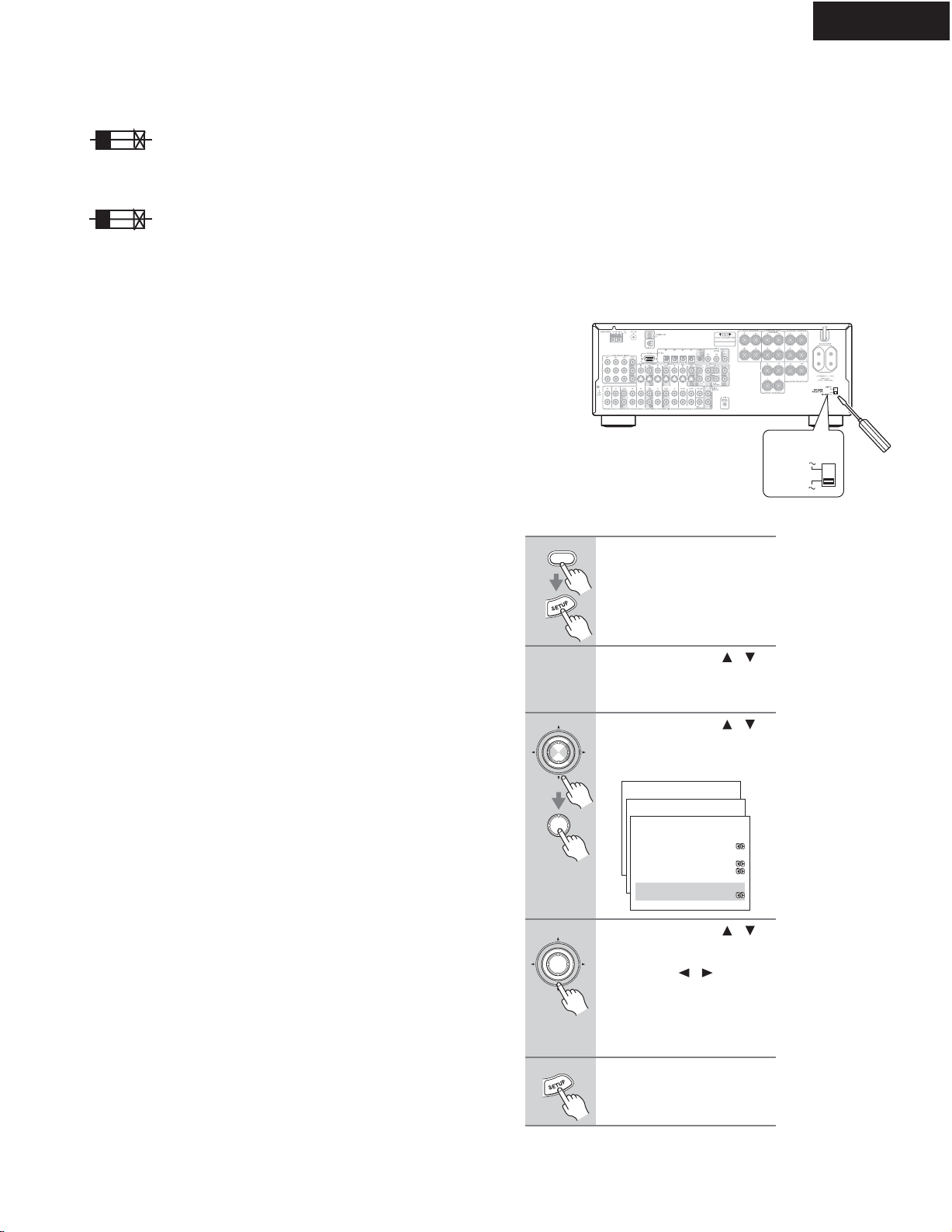
4.Setting the voltage selector (Worldwide models
only)
Worldwide models are equipped with a voltage selector to conform
with local power supplies. Be sure to set this switch to match the
voltage of the power supply in your area before plugging in the unit.
Determine the proper voltage for your area: 220-230 V or 120 V. If
the preset voltage is not correct for your area, insert a screwdriver
into the groove in the switch. Slide the switch all the way to the
upper (120 V) or to the lower (220-230 V), whichever is appropriate.
5.Setting the AM tuning step frequency
(Worldwide models only)
CIRCUIT NO. PART NO.
DESCRIPTION
Note: <D/C>:120V model only
<O>: Other models except 120V model
<WT>: Asian model only for 230V
120
V
VOLTAGE
SELECTOR
220-230
V
1Press the [RECEIVER] button fol-
lowed by the [SETUP] button.
The main menu appears onscreen.
2Use the Up and Down [ ]/[ ]
buttons to select"1. initial
Setup," and then press [ENTER].
The Initial Setup menu appears.
3Use the Up and Down [ ]/[ ]
buttons to select"3. Hardware
Setup," and then press [ENTER].
The Hardware Setup menu appears.
4Use the Up and Down [ ]/[ ]
buttons to select"d. AM Fre-
quency Step, and then use the
Leftand Right[ ]/[ ] buttonsto
select:
10 kHz: Select if 10 kHz steps are
used in your area.
9 kHz: Select if 9 kHz steps are used
in your area.
5Press the [SETUP] button.
The setup menu closes.
RECEIVER
ENTER
ENTER
Me n u
------------------------
1.Initial Setup
2. Speaker Set up
Adv a n c e d S e t u p
3. Sur r ound Set up
4. Audi o Adj ust
5. Li s t eni ng Mode Pr es et
6. Pr ef er ence
Bas i c Set up
1.Initial Setup
------------------------
2. Component Vi deo
3. Hardware Setup
1. Di gi t al I nput
1- 3. Har dwar e Set up
------------------------
:Not Activated
b. Sp I mpedance Mi ni mum
:6ohms
c. TV For mat : NTSC
d. AM Fr equency St ep
: 9kHz
a. Power ed Zone2
ENTER
F6901,F6902 252303 or 15A-TUL-250V or
252197 15A-UL/T-314,Fuse
F901 252196 or 12A-UL/T-314 or
252301 12A-TUL-250V <D/C/WT>
F902 252079 or 6.3A-SE-EAK or
252245 or 6.3A-SE-TL250V or
252279 6.3A-SE-TL250V,Fuse <O>
F903 252164 or 5A-UL/T-237 or
252258 5A-T/UL-ST2 <D/C>
252075 or 2.5A-SE-EAK or
252241 or 2.5A-SE-TL250V or
252275 2.5A-SE-TL250V <O>
F9501 252160 or 2.5A-UL/T-237 or
252254 2.5A-T/UL-ST2,Fuse <D/C>
252075 or 2.5A-SE-EAK or
252241 or 2.5A-SE-TL250V or
252275 2.5A-SE-TL250V <O>
TX-SR702/E
SERVICE PROCEDURES