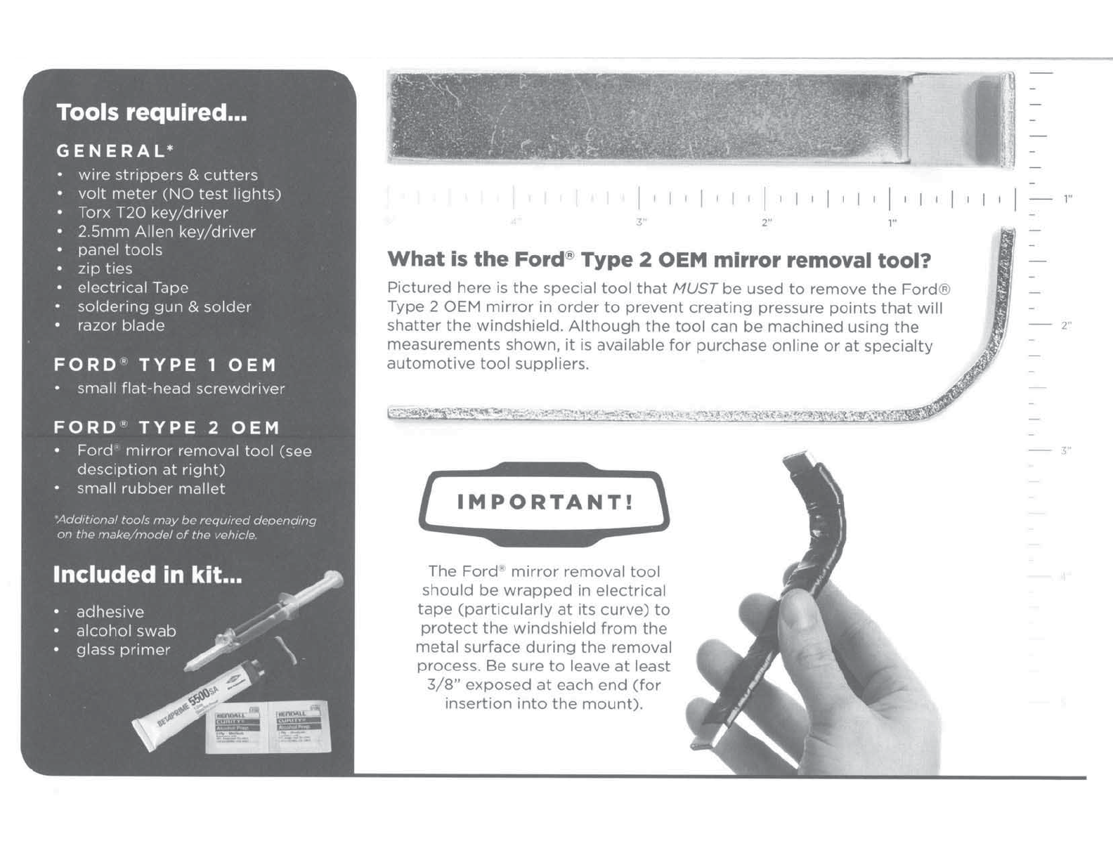
manuals.online logo
Brands
  1. Home
  2. •
  3. Brands
  4. •
  5. OnStar
  6. •
  7. Automobile Accessories
  8. •
  9. OnStar FMV User manual

OnStar FMV User manual

Star®
FMV
installation
instructions
Determining OnStar
FMV
Mirror
compatibility
...
The
OnStar
FMV
Mirror
is
NOT
designed
for
motorcycles,
RVs,
boats,
ATVs,
snowmobiles,
tractors,
go-karts,
etc. The
vehicle
must
be/have:
•
newer
than
model
year
1981
• a
passenger
vehicle
no
larger
than
a
light-duty
truck
under
85001bs
(gross
weight)
• a
windshield
angle
20-50
degrees
(for
mirror
adjustability
and
proper
crash
detection)
•
no
cracks
anywhere
in
the
windshield
and/or
chips
near
the
mirror
mount
• a
proper
mirror
mount
("big
foot")
and/or
a
mount
adaptor
as
listed
in
Section
A
Removing
the
OEM
Rear
View
Mirror.
•
clearance
to
allow
the
top
of
the
OnStar
FMV
Mirror
transmittal
access
to
the
sky
through
the
windshield
when
mounted
(if
not,
an
external
GPS
antenna
must
be
used).
•
no
metallic
tint
on
the
front
windshield,
remove
metallic
based
tint
before
install.
•
able
to
be
fully
adjusted
for
all
drivers
(e.g.
not
interfere
with
visors,
console,
etc.)
IMPORTANT:
Remote
start/keyless
entry
antennas,
road
quick-pass
devices
or
other
similar
transmit/receive
units
WILL
interfere
with
the
ability
to
acquire
a GPS signal.
Relocate
such
devices
at
least
one
(1)
foot
away
from
the
OnStar
FMV
Mirror.
Before you begin...
First, consult
the
compatability
requirements listed above. Once
compatability
is
confirmed,
request
the
following
information
from
the
customer
BEFORE
proceeding
with
installation
of
the
OnStar FMV Mirror*:
•
vehicle
make/model/year
and
VIN
•
customer
name,
address
&
phone
number
of
designated
OnStar
account
holder
+ OnStar
phone
number
will be provisioned based
on
customer
phone
number
provided.
•
OnStar
Station
ID (STID)
+ Capture
ALL
information
on
the
bottom
of
the
OnStar
FMV
Mirror
box,
including
STID.
+ IMPORTANT:
DO
NOT
confuse
STIDs
if
performing
multiple
installs.
*These
items
are
required
for
the
installer
to
perform
the
online
registration
of
the
OnStar
FMV
Mirror.
IMPORTANT: Read these instructions completely BEFORE
beginning installation
of
the OnStar FMV Mirror!
[
IMPORTANT!
~
Installing
the
OnStar
FMV
Mirror
may
result in
the
loss
of
some
features
embedded
within
the
OEM
mirror
including
(but
not
limited
to):
mirror
dimming;
audio
commands
for
systems like Ford
SyncR,
U-Connectp,
or
other
Bluetooth
R systems;
compass;
map
lights;
video
displays;
garage
door
openers.
Before
proceeding
with
OnStar
FMV
Mirror
installation, make sure
the
customer
is
aware
of
these
potential
feature
losses
within
their
particular
vehicle.
DO
NOT
remove
an
OEM
mirror
with
an
embedded
safety
feature
such as
passenger-side
airbag
indicator, lane
departure
sensor,
back-up
camera display,
or
any
component
that
will
trigger
a
diagnostic
trouble
code.
For the latest information
regarding FMV fit criteria visit:
onstar.com/fitcriteria
NOTE:
You
MUST disable
(without
reminder)
911
ASSIST'M in the phone
settings
of
the
Ford
Sync·•
system
for
Forcr' vehicles
equipped
with
the
Sync···
system.
I I I
I
I
I
I
I
I
I
I
I
I
I
I I
I
I I I
3
2"
,.
What
is
the
Ford!,
Type
2 OEM
mirror
removal tool?
P1ctured here
is
the
special
tool
that
MUST
be
used
to
remove
the
Ford
,
~
'
Type 2 OEM
mirror
in
order
to
prevent
creating
pressure
points
that
will
shatter
the
windshield.
Although
the
tool
can
be
machined
using
the
measurements shown,
it
is
available
for
purchase
online
or
at
specialty
automotive
tool
suppliers.
IMPORTANT!
The
Ford"
mirror
removal
tool
should
be
wrapped
1n
electncal
tape
(particularly
at
1ts
curve)
to
protect
the
windshield
from
the
metal
surface
dunng
the
removal
process. Be sure
to
leave
at
least
3/8"
exposed
at
each
end
(for
msertion
into
the
mount).
1"
2"
-
3'
Types
of
mounts...
Below
are
the
three
typ
es
of
mou
nt
s
you
will
see
on
ce
the
OEM
mirror
is
remo
v
ed
,
as
well as
the
a
dapt
or
th
at
may
be
necessary in
ord
er
to
pro
ce
ed
with
ins
tallati
on.
BIGFOOT
MOUNT
An
adaptor
IS
NOT
required
.
SMALLFOOT
MOUNT
An
adaptor
IS
required
.
CAM
LOCK
MOUNT
An
adaptor
IS
required.
Because
it
has
enough
surface area
to
support
the
weight,
the
OnStar FMV
Mirror
can
simply
be
slid
onto
this
mount.
Because
of
its
l
im
i
ted
surface
area, a
smallfoot
mount
adaptor
IS
required
before
installing
the
OnStar
FMV Mirror.
Because
of
its
unique
shape, a
cam
lock
mount
adaptor
IS
required
before
installing
the
OnStar
FMV
Mirror.
Glossary...
VBATT
orB+
(Yellow
Wire)
A
direct
positive
12-volt
power
from
the
battery,
this line is
ALWAYS active.
Gnd
(Black
Wire)
The
GROUND side
of
the
battery.
The
metal
chassis
of
the
vehicle
is
used
as
ground
in
most
cases;
however
there
may
be
ground
lines
present
in
the
vehicle.
Accessory
or
ACC
(Red
Wire)
A
positive
12-volt
power
line
that
is ONLY
active
when
the
ignition
of
the
vehicle
is in
ON/RUN
or
ACC
(if
available)
and
is
inactive
when
the
ignition
is in
CRANK
or
OFF
positions.
DTC
(Diagnostic
Trouble
Code)
See
the
trouble-shooting
guide;
there
is an issue
with
the
OnStar
System,
device
or
components.
UAC
(User
Access
Controls)
A
menu
used
to
access
diagnostic
information
as well
as
to
configure
the
OnStar
device. See UserAccessed Controls
(UAC)
section.
BUB
(Back-Up
Battery)
In
the event
of
vehicle
power
loss
after
a collision,
the
device
would
be
able
to
place an
emergency
call
to
the
OnStar
Call
Center;
audio
components
(speakers, microphone, etc.)
and/or
any
lighting
(icons, backlighting,
etc
.) are NOT
powered.
U
.,.
Ok
0 Removing
the
existing OEM rearview mirror...
There are
primarily
three
different
mounting
op
tions
used
by
vehicle
manufactur
ers.
Once
you
identify
which
type
of
mount
is
used
in
the
vehicle,
carefully
proceed
with
removal
of
the
existing
mirror
as follows:
1.
Screw
wedge
mount
o Using a screwdriver
or
Torx bit. loosen
the
screw
in
the
base
of
the
mirror
mount.
o
After
loosening
the
screw,
gent
ly
lift
upward
to
slide
the
mirror
off
of
the
mirror
mount.
2. Screwless
wedge
mount
(Ford
'"vehicles ONLY):
FORO
'
OEM
TYPE
1
• Using a
smalll/8"
flat-head screwdriver, insert
the
flat
end
into
the
opening
at
the
bottom
of
the
mirror
mount.
o Staying flush
with
the
windshield, slide
the
screwdnver
into
the
center
of
the
mirror
mount
until resistance
is
felt.
o
Gently
apply
a small
amount
of
additional
upward
force
to
lift
away
the
locking
spring
in the
mount.
• While still
app
lying
upward
pressure
with
the
screwdriver, grasp
the
mirror
bracket
and
wiggle
side
to
side.
•
Lift
mirror
up
toward
the
headliner
and
off
of
the
mirror
mount
button.
• IMPORTANT;
BE
VERY
CAREFUL!
TOO
MUCH
FORCE
CAN
CAUSE
DAMAGE
TO
THE
WINDSHIELD
.
FORO
'
OEM
TYPE
2
• Insert
the
CURVED end
of
the
Ford
mirror
removal
tool
(see above)
into
the
bottom
of
the
mirror
channel mount.
• GENTLY
pry
the
tool
to
release
the
spring clip.
o IMPORTANT: Ensure
the
clip
Is
fully
disengaged
from
the
mirror
mount
before
attempting
to
remove
the
mirror.
• Use a small
rubber
mallet
to
gently
tap the
base
of
the
mirror
channel
mount
upwards
towards
the
headliner.
• IMPORTANT:
BE
VERY
CAREFUL!
TOO
MUCH
FORCE
CAN
CAUSE DAMAGE
TO
THE
WINDSHIELD
.
3.
Cam lock
mount
(no
tools required)
• Grasp the base
of
the
mirror.
• Rotate
90
degrees
counte
rclockwise.
• Slide
the
mirror
down
toward
the
dash
to
remove.
0 Affixing
the
mount
adaptors...
Skip
to
section
C
if
vehicle has a
bigfoot
mount.
If
it
does
not
have a
mount
of
any sort, refer
to
the
section
on
the
back
of
this
page
detailing
how
to
install
the
bi
gfoot
mount.
DO NOT USE EXPIRED PRODUCT. Check
the
exp
1ration
date
on
both
the
adhesive.
pnmer
(Oay.Month.Year
format)
and
the
alcohol
wipe.
If
the
product
hasexp1red,
do
not
use
1t.
PROTECT THE VEHICLE'S INTERIOR! The
SSOOSA
primer
will
DRIP
AND
STAIN!
Completely
cover
the
work
area
in
the
vehicle.
Cat
ch
ALL
drips
with
paper
towel
in
your
free hand.
The
primer
will
instant
ly
soak
through
layers
of
paper
towel/fabric/etc.,
so
you
MUST
properly
protect
the
vehicle Interior.
Using
plastic
sheetmg
underneath
an
absorbent
material
is
highly
recommended
to
protect
the
vehic
le
intenor.
WEAR
SAFETY EQUIPMENTI
Wear
nitrile
chem
•
cal
resistant
gloves
(the
5500SA
primer
will
sta•n
your
hands).
safety
glasses,
work
apron.
or
other
protect
i
on
required
or
provided
by
your
company.
Work
in
a
WELL
ventilated
area (leave
doors
and
w1n
·
dews
of
the
vehicle
open)
between
so•F
and
as•F.
1.
Cleaning and prepping windshield and
mount
adaptor.
Scrape
the
windshield
with
a
razor
blade
to
remove
any
residue
or
contaminates
(may be clear and notvisible
by
the naked eye)
Mask
off
the
area
Sltde the appropriate mountadapter onto the existing mirror mount on the windsh•eld
• For the brgfoot service mount application,
see
Instructions on reverse
Use
blue painter tape
or
standard masking tape
•
Tape
around theadapter
so
when the black primer
Is
applied, the tape maskmg
w1ll
help ma.ntarn aclean protessronallook
to
the
black pnmer that will
be
applied
in
later steps
Remove
adapterafter tape
Is
applied
+
Make
sure the
mask1ng
has aclean strarght edge
Clean
the
glass
and
mount
adapter
W1th
provrded alcohol
wrpe:
(others may contarn additives that may affect the bondmg, only
us-.
the provided wrpe)
+ Thoroughly clean
th<l
glass Inside the masked
area.
let flash
off
(1
minute)
+ Thoroughly clean the channels
of
theadapter or the back
of
the brgfoot mount. let flash
off
(I minute)
DO
NOT
TOUCH
glass or the adapter/mount once they are cleaned
Prime
glass
surface
(CAREFUL:
The
primer
will
drip
and
stain)
Cover
the
dashboard
to
avo1d
damage
from
dnps
Shake
BETAPRIME~
SSOOSA
Glass/Frit Primer for at least one
(1)
minute beforeapplication
Open
BETAPRIME'•
SSOOSA
by
screwrng the t•P/felt applicator 10 clockwise, usea papertowel
to
catch drips (Jt
WJ/1
stam
anything
Jt
contacts)
Apply the primer
to
th~
inside
of
the taped/masked
olt
square on the
wlndshoeld
+ It the pnmer runs
outs1de
or the maskea
area.
th~>
prrmer run can
bP
scraped
off
w1th" razor blade once It has dried
Allow a
minimum
of
six
(6)
minutes for primer to
dry
before applying the
adhl?slv<:>
2.
Attach the appropriate
mount
adapter.
SMALLFOOT
MOUNT
ADAPTOR
Slide
the
small
foot
mount
adapter
DOWN
onto
the
small
foot
mount
on
the
windshield
of
the
vehicle
.
Ensure
the
adapter
is sea
ted
all
the
way
down
onto
the
mount.
IMPORTANT:
If
there
•s
a
1/8"
or
large
gap
between
the
adapter
and
the
windshield. usea
folded
p1ece
of
electncal
tape
to
wedge
between
the
windshield
and
the
top
center
of
the
adapter
(as
shown
below);
use
enough
layers
of
tape
to
ensure a
snug fit. This
will
prevent
the
adhesive
from
flow
ing
1nto
th1s
area
so
there ls
enough
adhes•ve
to
fill
both
channels.
IMPORTANT:
Apply
electrical
tape
al
ong
the
sides
and
top
of
the
mount
adaptor;
use a
flat
edged
tool
to
make
a
tight
seal
between
the
tape
and
windshield
to
keep
adhesive
from
squeezing
out
when
Injecting
the
adhesive(reverse
angle
above
right).
CAM
LOCK
MOUNT
ADAPTOR
Slide
the
cam
lock
adapter
UP
into
the
cam
lock
mount
on
the
windshield
of
the
veh1cle.
Ensure
the
adapter
is seated all
the
way
up
into
the
mount.
Tighten
the
set
screw
hand
tight
using a
1/64"
Allen
wrench.
IMPORTANT:
If
the
adapter
starts
to
push
way
from
the
windshield,
it
Is
too
tight.
IMPORTANT:
Apply
electrical
tape
along
the
sides
and
top
of
the
mount
adaptor.
use a
flat
edged
tool
to
make
a
tight
seal
between
the
tape
and
w•ndsh1
eld
(as
shown
below
nght)
to
keep
adhes1ve
from
squeezing
out
when
InJeCting
the
adhesive.
3.
Apply
the
adhesive.
IMPORTANT:
The
adhes•ve
starts
to
set
w•thin
5·10
mmutes
of
application.
Cover
the
dashboard
to
avoid
damage
from
drips
.
Using ONLY
the
adhesive
provided
(3M-DP604NS), insert the syringe
Into
the fill holes
at
the
top
of
the
adapter
and SLOWLYdepress
the
plunger
until approximately
1/2
of
adhesive remains In
the
syringe
IMPORTANT:
The
cam
lock
mount
adaptor
uses TWO syringes; depress each J
plunger
until
approximately
1/4
of
adhesive remains
in
the
syringe.
Make sure
both
channels are filled entirely
by
usmg
half
of
the
adhesive in each
channel (small
fool
adapter)
or
3/4
of
the
adhesive
from
each synnge
in
eachchannel
(cam
lock
adapater).
You
must
makesure
the
adapter
is
properly
masked
off:
if
there
Is
too
muchsqueeze
out
of
adhesive
you
will
not
have enough
to
fill
both
channels (
After
10
minutes, remove
the
tape
and
usearazor blade
to
remove any adhesive
that
may
have escaped.
IMPORTANT:
Though
the
original
mount
will
hold
the
we1ght
of
the
adapter
and
the
OnStar
FMV
Mirrorwhile the adhesive sets.
allow
at
least
20
minutes
for
the
adhes1ve
to
fully
cure
at
room
temperature before
dnving
the
vehicle.
.' .
GPlugging-in
the
Back-Up
Battery
(BUB)...
1.
Remove Allen screw
(2.5mm)
from
speaker
door
on
the
back
of
the
mirror
and remove
door
2. Plug in the Green
Battery
Pack
into
the
circuit
board
(make sure
it
locks
into
place).
3 Re-Install the
door
,ensuring the wires are safely
tucked
into
the
cavity
under
the plastic between housing and
circuit
board.
4. Hand Tighten
the
Allen screw till snug
(do
not
over
tighten)
IMPORTANT
:
Be
careful
not
to
strip
the hole.
If
you
do, use a slightly
larger
screw,
but
NOT
longer
than
the
screw
provided
.
IIC11\,;""
GAttaching
the
OnStar
FMV
Mirror & connecting
power
...
Slide the
mirror
onto
the
mount
or
fully cured
mount
adaptor, being certain
to
FULLY seat the
mirror
on
mount
and
tighten
the
Torx
(T20)
set
screw. Be sure the screw is snug (l.SN-m/16
lb-in)
.
•
If
mirror
or
adapter
Will
not
slide
onto
the
wedge
mount
on
the
windshield. check
for
any
oxidation
on
the
mount
and remove
the oxidation;
apply
a small
amount
of
white
lithium
grease
to
aid
in
mounting.
To
co
n
nect
po
wer to
the
O
nStar
FM
V Mi
rr
or, f
ollo
w these steps:
1.
locate
the
appropnate
vehicle
power
wires
in
the veh1cle
(B+
[Battery
12V]. ACC[Accessory/switched 12V],
Gnd[Ground]).
Ensure
that
the
VBATT and Gnd Wtres are
actually
a constant
connection
and
do
not
change
when
cranking,
dome
lights
on/off.
doors
open/closed, changing gears, park/reverse/drive.
(Note:
Power
lines
to
dome
lights
in
most
vehicles
turn
off
after
a
period
of
t1me
of
the
vehicle
being
off;
do
NOT
connect
to
such lines.)
2. Route the
wire
harness
(B+
[yell
ow].
ACC
[red]
and
Gnd
[black])
from the
mi
r
ror
to
the
power
source either along the
headliner and
down
the A-pillar
or
into
the headliner.
• Secure all wires along the entire
length
of
the
harness avo1dlng any
audio
or
antenna wires/cables while
making
sure
to
avoid sharp
metal
and
not
to
interfere
with
any
moving
parts
or
heal
sources such as steering, braking.
lighting
or
safety
equipment
(i.e. atrbags, seatbelts)
3. Find and use an OEM
ground
connection
or
create a SECURE
ground
connection
by
screwmg
into
the
vehicle's
metal
chass1s
(venfy
the
metal
is a
low
resistance
ground
point).
removing any
paint/coating
for
good
connectivity.
IMPORTANT:
Do
not
tamper
with
or
hinder any safety equipment
such
as
Side Curtain Airbags
(i.e. zip-tie and secure all wires near an airbag and NEVER route wires over the path
of
the airbag).
4.
Disconnect the negative terminal
of
the
vehicle's battery.
5. Make the
appropria
t
ed
wire splices and
connect
the B+
and
ACC wires:
Use an
In
line splice.
• Spread the
wire
strands.
• Insert the OnStar FMV
Mirror
wire
and
twist
together.
• Solder the connection.
Zip-tie
the lines
together
to
provide
strain relief.
• Thoroughly wrap electrical
tape
around the connection.
•
If
the provided harness is
too
long, bundle
the
wiring
and make sure
it
does
not
entangle other wires
or
cause a rattle -OR-
cut
to
the
appropr
i
ate
length
and
sever the lnline fuse(s) from
the
end
and
splice th
em
(an inline fuse MUST be used).
0 Mounting
the
external microphone...
Mount
the
mic
in
one
of
the
locations
indicated
in
the
User Access
Controls
section
on
reverse.
OnStar
recommends
adhering
the
microphone
to
a
plastic
trim
piece
if
possible;
however
it
can
be
applied
to
a headliner surface
if
necessary.
For
plastic surfaces.
thoroughly
clean
the
area
with
an alcohol
wipe
and
dry:
to
mount.
remove
the
adhesive tape backing,
then
press
and
hold
the
mic
firm
to
the
surface
for
20
seconds
IMPORTANT: The adhesive on
the
external microphone
Is
meant
for only ONE application.
Be
careful.
1t::fl
..
0 Registering
the
OnStar
FMV
Mirror...
1.
Reconnect
the
negative terminal
of
the
vehicle's battery.
• For warranty
part
replacement
or
vehicle transfer Information. see
the
Troubleshooting section.
2.
After
all
power
is
connected
(POWER CONNECTIONS MUST BE CHECKED):
• Turn
the
vehicle on
and
press
the
WHITE
phone
button.
"OnStar Ready" should be
heard
.
• Press
the
phone
button
again
and
"Thank
you.
Goodbye"
will be heard.
• With vehicle
OFF.
repeat last
two
steps The
unit
should be
tn
stand-byand "wake
up"
if
constant power
is
connected correctly.
• Ensure
when
the
vehicle is
turned
ON
and
OFF
the
OnStar
FMV
Mirror
does
the
same: then Leave
the
vehicle ON.
•
If
the
external
microphone
is
not
plugged
in (see
below),
a DiagnostiC Trouble Code (DTC)
will
be
set.
(red
telltale).
• A solid
yellow
Alert
(triangle)
Icon indicates
the
unit
has
not
been
registered.
proceed
to
step
3.
•
If
the
unit
does
NOT
have an illuminated
Alert
Icon, this means
it
has
been
registered
before
(i.e. returned
unit
or
vehicle
transfer); skip
step
3
and
press
the
BLUE OnStar
button
to
register
the
mirror
to
the
new
customer.
IMPORTANT: The OnStar Mirror MUST
be
ON
for the registration
to
be
successful.
3.
Leave
the
Veh1cle/OnStar FMV M1rror
ON
and
THEN
complete
the
Web
Registration:
• Go
to
www.OnStar.com/web/portal/fmv/reglstration.
• Enter information collected earlier; ensure
correct
STID is attached
to
the
ap
prop
riate vehicle/customer.
4
After
the Web Registration is submitted. leave
the
vehicle
ON
until
the
Alert
Icon extinguishes: this should
turn
off
in less than
15
minutes.
If
the
Alert
Icon
does
not
go
off
after
20
Minutes, press
the
BLUE OnStar
button
TWICE
to
complete
the
reg1strat1on
(Note
:
The
unit/vehicle
must
be
m a CellularData coverage area
for
the
automated
web
reg1strat1on
to
be
successful.)
uct
"
0
Final steps...
1.
Reinstall all removed panels and ensure vehicle is
back
to
its
original
condition
or
better
2.
Set
Audio
Tuning Parameters:
• Press and
hold
the Phone
button
for
5 seconds
to
enter
User Access Controls.
• Say
NO
to
all
the
prompts
until
you
hear
"Your
current
hands free
tuning
is
set
to
# .
Would
you
like
to
change
this
setting?"
• Say
YES
and
choose
the
appropriate
tumng
parameter (see
chart
on
reverse
in
UserAccess Controls section).
Once
complete.
press
the
WHITE
phone
button
again
to
exit.
3. Check
to
ensure
the
vehicle
can
recetve a
GPS
signal:
• Move
the
vehicle
into
an
open-sky
environment.
let
the
vehicle sit
for
1-2
minutes.
• Press
and
hold
the
PHONE
button
for
five
(5)
seconds
to
the
enter
the
User Access Controls (see reverse).
•
Under
D1agnost•cs>GPS, ensure
the
unit
has a
'Current"
location
(if
not. see Troubleshooting Guide
on
reverse).
4.
Install
the
provided
OnStar FMV
window
clings/stickers
of
front-side
windows
IMPORTANT: Inform the customer that they
MUST
press the
BLUE
OnStar
button
to
complete
the
enrollment
of
their account
and choose their OnStar Services Package.
Without
doing
so, OnStar cannot guaranty any services will
be
provided.
Congratulations! Installation
of
the
OnStar FMV Mirror
is
now
complete. Star'
FMV
User Accessed Controls
(UAC)
...
This menu
is
used
to
access diagnostic information
as
well
as
to
configure
the
OnStar
device.
1.
Press
and
hold
the
"Phone
Button"
for
5
seconds.
2.
You
will
hear
"Welcome
to
OnStar
9.0.
Continuing
will
change
your
settings
of
your
OnStar
system
...
".
3.
There
will
be
a
list
of
options
that
you
can
choose
from
by
saying
"Yes"
or
"No":
CHANGE
YOUR LANGUAGE
changes
your
Language
for
all
menus
VERIFY
HANDS-FREE
CALLING DATA
information
related
to
the
OnStar
Hands-Free
calling
phone
REPROGRAM YOUR HANDS FREE
CALLING
DATA use
ONLY
if
requested
by
OnStar
Technical
Assistance
HANDS-FREE
TUNING
SETTINGS
changes
setting
for
different
mic
positions:
TUNING
ROW
EXTERNAL
MIC LOCATION
0
DO
NOT
USE
1
(default
setting)
BEST: mic
is
near driver
to
the
side
of
overhead center console
2 BETTER: mic
is
near
the
front
of
headliner near windshield
3 CONVERTIBLE: with mic near
top
of
A-Pillar
4 CONVERTIBLE:
with
mic near
the
front
of
headliner near windshield
5
DO
NOT
USE
DIAGNOSTICS
diagnostic
info
for
the
OnStar
unit
(with
sub-categories):
• TROUBLE CODES (SAY "1")
+
Some
trouble
codes
are
provided
in
the
Trooubleshooting
section
below;
for
other
codes
not
listed,
please
contact
technical
support
at
1.877.733.6770.
• CELLULAR (SAY
"2")
+ Signal
Strength
(Scale: 51Dbm
to
-103Dbm,
the
lower
the
number
the
better
the
signal)
+
System
ID
+
Preferred
Roaming
List
(PRL):
used
for
roaming
purposes
+
Mobile
Device
Number
(MDN):
phone
number
for
the
OnStar
Hands
Free
Calling
+
Mobile
Identification
Number
(MIN):
10-digit
unique
number
used
to
identify
a
mobile
phone
+
Packet
Data
(available
or
unavailable):
based
on
the
cellular
coverage
area
you
are
currently
in;
must
be
available
to
be
able
to
download
turn-by-turn
route
or
perform
Web
registration.
• BLUETOOTH (SAY
"3")
+
Enabled/Disabled
+
Link
Quality
of
Currently
Paired
Device
(Scale: 0
to
255;
Higher
the
number
the
better
the
link
quality)
• GPS (SAY
"4")
+
Aged/Current:
if
aged
there
is
no
GPS signal;
this
will
be
true
if
the
vehicle
is
inside
+
Latitude/Longitude:
the
devices
current
or
last
known
location
+
Time
Stamp:
YEAR/MONTH/DAY/HOURS(24hr
scale)/MINUTES/SECONDS
Note:
it
will
read
only
numbers
back
with
no
pause
(example:
Feb
21,
2011
4:42
PM
=
20110221284200).
Alert
Icon Legend...
TELLTALE STATUS
ALERT
ICON
STATE
CONDITION
Green Telltale
Red Telltale
NONE
STEADY
FLASHING
STEADY
Troubleshooting Guide...
CONDITION/PROBLEM
No
power
Only
turns
ON
when
button
is
pressed
Green Telltale
with
Solid
Alert
Icon
Red Telltale
with
Flashing
Alert
Icon
No
or
low
audio
No
backlighting
No
GPS signal
Speech
recognition
does
not
hear
spoken
commands
or
audio
cannot
be
heard
from
other
end
of
phone
calls
Replacing
the
OnStar
FMV
Mirror
(warranty
,
etc
.)
Moving
the
OnStar
FMV
Mirror
to
a
new
vehicle
Un
stable/vibrating
image
in
the
mirror
Troub
le
Code
944603
Trouble
Code
944704
Other
Trouble
Codes
system
functioning
and
enrolled/registered
with
OnStar
system
functioning
but
NOT
enrolled
/
registered
with
OnStar
DTC Set• -
trouble
with
the
mirror
DTC
Set•
-
trouble
with
the
mirror
and
NOT
enrolled
/
registered
with
OnStar
'See
UAC
section.
SOLUTION
Check
the
inline fuses
of
the
wiring
harness;
replace
if
fuse
is
blown
(a
blown
fuse
indic
ates a
short
in
the
wiring)
;
inspect
the
entire
length
of
wiring
for
cuts
or
abrasions.
Using
a
digital
multi-meter,
check
both
VBA
TT
and
ACC
for
+12V
power.
Check
the
ground
connection
and
ensure
that
it
is
secure
and
has a
good
connection
(i.e.
no
paint
on
the
metal
,
etc
.).
If
no
wiring
issues are
found,
there
is
a
remote
possibility
of
a
locked-up
unit.
Remove
power
from
the
mirror,
wait
20
seconds
and
reconnect
power. If
there
is
still
no
power, replace
the
OnStar
FMV
Mirror
with
a
new
one.
If
the
old
OnStar
FMV
Mirror
was enrolled,
transfer
the
account
to
the
new
device.
This
indicates
that
the
accessory
line
is
not
functioning.
Check
the
inline
fuses
of
the
wiring
harness;
replace
if
fuse is
blown
(a
blown
fuse
indicat
es a
short
in
the
wiring);
inspect
the
entire
length
of
wiring
for
cuts
or
abrasions.
Using
a
digital
multi-meter,
check
ACC
for
+12V
power
when
the
vehicle
is
in
the
ON
or
RUN state.
The OnStar Unit
Is
NOT configured.
Complete
the
online
registration
in
the
Installation
Guide
. If
that
was
already
performed,
wait
25
minutes
after
it
was
submitted
wit
h
the
OnStar
FMV
Mirror
in
the
ON
mode
. (Failure
of
the
Web
registration
may
be
an
indication
that
the
vehicle
is
not
in a
cellular
data
coverage
area;
some
metal
structures
/
buildings
can
also
block
cellular
signals.)
If
the
Alert
I
con
is
still on, press
the
OnStar
Blue
Button
twice
and
it
will
connect
you
to
an
advisor
who
will
complete
the
registration.
There
is a
trouble
code
active
(e.g.
there
is a
problem
with
the
unit).
Trouble
codes
can
be
pulled
from
the
unit.
See
the
User
Accessed
Controls
(UAC)
section
for
more
details.
Turn
up
the
sound
us
ing
volume
up
button.
If
there
is sti
ll
no
so
und
;
remove
the
speaker
cover
and
c
heck
that
the
speaker
connected/plugged
into
to
the
circuit
board
(red
and
black
twisted
wires).
Increase
the
backlighting
using
the
light
bulb
button.
(When
at
the
lowest
le
vel,
the
backlighting
goes
off
completely
.)
Ensure
there
is a
clear
view
of
the
sky
through
the
windshield
from
the
top
of
the
mirror.
Metallic-lined
window
tint
will
block
GPS
reception;
if
present,
remove
from
windshield.
RF
interference
from
some
devices
can
block
/
jam
the
GPS
chipset
of
the
OnStar
FMV Mirror;
check
for
devices
near
the
OnStar
FMV
Mirror
that
may
cause this
kind
of
interference, such
as
(but
not
limited
to)
remote
start/keyless/alarm
antennas,
toll
pass devices,
or
anything
that
can
create
an
RF
signal. If
said
devices
are present,
relocate
away
from
the
OnStar
FMV
Mirror
and
re-test
for
GPS
signal.
Indicates
microphone
is
not
working.
Check
the
length
of
the
microphone
wiring
for
any
cuts
or
pinches.
Ensure
inline
connector
and
the
connector
on
the
back
of
the
mirror
are
connected
and
fully
seated.
Verify
microphone
is
working
by
using speech recognit
ion
(press PHONE
button
and
speak a
command).
.
Install
the
new
OnStar
FMV
Mirror
.
.
Pre
ss
the
OnStar
Blue
Button
twice.
(DO
NOT
USE
WEB
REGISTRATION.)
Tell
the
advisor
this
is
a
"part
replacement.
"
Give
the
advi
so
r
the
OnStar
Station
ID
(STID)
fr
om
the
old
mirror
(located
on
neck).
The
advisor
will
transfer
all
account
information
and
configure
the
new
mirror.
.Install
the
OnStar
FMV
Mirror
in
the
new
vehicle
.
.
Press
the
On
Star
Blue
Button.
(DO
NOT
USE
WEB
REGISTRATION.)
.Tell
the
advisor
this
is a
"vehicle
transfer."
.
Give
the
advisor
the
new
vehicle
information
.
.
The
advisor
will
transfer
all
account
information
.
This
indicates
the
mirror
is
not
fully
seated
onto
the
mount
.
Loosen
the
set
screw
on
the
base
of
the
OnStar
FMV
Mirror
and
wiggle
the
mirror
base
to
ensure
it
is
FULLY
seated
onto
the
mount;
re-tighten
the
set
screw
.
Backup
Power
Source
-
Voltage
Below
Threshold
Th
is
means
the
Back-Up
Battery
(BUB)
has
gone
bad
;
replace
the
BUB.
When
the
new
battery
is installed,
it
can
take
up
to
30
minutes
with
the
vehicle
ON
to
clear
the
DTC.
If
the
problem
persists
with
the
new
battery,
contact
Technical
Support
at
1.877.733.6770.
Backup
Power
Source-
Open
Circuit
Check
that
th
e
OnStar
FMV
Mirror
back-up
battery
is
plugged
in. If
battery
is
plugged
in a
nd
code
9447
still present,
replace
BUB.
Please
Contact
Technical
support
at
1.877.733.6770.
Affixing
a
bigfoot
mount
...
IMPORTANT:
If
the
windshield
is
equipped
with
a
blackout
area
around
the
mirror
base
bracket,
care
must
be
used
not
to
cut
or
scrape
the
blackout.
1.
Determine
the
location
of
the
mirror
mounting
base
by
marking
the
outside/inside
of
the
windshield
with
a
wax
pencil
where
the
base
was
previously
located
.
If
it
is
not
clear
where
the
base
was
located,
or
if
there
was
not
a
mount
previously
there, use
the
following
steps
to
determine
where
the
base
should
be
installed:
1.1.
Using
a
measuring
tape
,
measur
e
the
distance
between
the
windshield
pillar
s
at
the
windshi
e
ld
blackout
line.
1.2
Using
a
marking
pen
c
il
,
halfway
between
the
windshield
pillars,
draw
a
centerline
(1)
on
the
windshield
from
the
ro
of
panel
to
the
windshield
base.
1.3
Dr
aw
a
perpendicular
line
inter
se
cting
the
centerline
(
2)
at
that
lo
cation
. This
location
can
be
determined
by
holding
the
mirror
ins
ide
the
vehicle
at
the
proper
lo
cation
.
NOTE: The
bottom
center
of
the
bigfoot
mount
will
be
at
the
intersection
of
these
lines.
2. Clean
the
inside
windshield
glass
thoroughly
with
a
razor
blade
to
remove
any
old
adhesive.
3.
Mask
off
the
area.
using
blue
painter
's
tape
or
standard
masking
tape
to
mask
off
a 2
inch
square
for
where
the
black
primer
will
go
.
IMPORTANT: Clean
the
inside
windshield
glass
and
the
mounting
surface
of
the
mirror
mounting
base
thoroughly
with
the
provided
alcohol
wipes.
DO
NOT
touch
the
mounting
surface
of
the
mirror
mounting
base
or
the
glass.
4.
Cover
dash
and
other
areas
to
prevent
primer
or
adhesive
spills
on
those
surfaces.
5.
Prime
glass
surface
(CAREFUL: The
primer
will
drip
and stain)
Cover
the
dashboard
to
avoid
damage
from drips.
Shake BETAPRIME
'M
SSOOSA Gla
ss
/
Frit
Primer
for
at
least
one
(1)
minute
before
application
Open
BETAPRIME
'M
SSOOSA
by
screwing
the
tip/felt
applicator
in
clockwise
, use a
paper
towel
to
catch
drips
(it
will
stain
anything
it
contacts)
Apply
the
primer
to
the
inside
of
the
taped/ma
s
ked
off
square
on
the
windshield
+
If
the
primer
runs
outside
of
the
masked
area,
the
primer
run
can
be
scraped
off
with
a
razor
blade
once
it
has
dried
Allow
a
minimum
of
si
x
(6)
minutes
for
primer
to
dry
before
app
l
ying
the
adhesive
IMPORTANT:
DO
NOT
touch
the
mounting
surface
of
the
mirror
mounting
base
or
the
glass.
6.
Using
the
syringe,
apply
the
adhesive
to
the
back
side
of
the
bigfoot
mount
in a
back
and
forth
zigzag
pattern.
7.
Apply
the
bigfoot
mount
to
the
windshield,
ensuring
that
the
mount
aligns
correctly
to
the
area
that
was
primed
with
the
black
primer.
B.
Hold
the
mounting
base
firmly
in
place
for
one
(1)
minute
.
B.
Affix
the
mount
to
the
glass
using
a
few
strips
of
electrical
tape
or
masking
tape
.
9. Clean
the
wax
pencil
lines
from
the
exterior
surface
of
the
glass.
10.
Wait
thirty
(30)
minutes
and
remove
the
tape
and
scrape
away
the
excess
adhesive/primer
with
a
razor
blade
.
IMPORTANT: Install
the
OnStar
FMV
Mirror
after
60
minutes
(one
hour)
onto
the
bigfoot
mirror
mount.
Refer
to
Section
D
to
attach
the
OnStar
FMV
Mirror
.
For installation technical support,
call1.877.733.6770.
2
TTY
is
available
for
the
hearing
impaired
via a
dedicated
toll-free
line
at
1.877.248.2080.
For general information
about
the
OnStar
FMV
Mirror, call1.855.
ONSTAR3 (1.855.667.8273) or visit
onstar.com/web/portal/onstarfmv.

Other manuals for FMV

1

Other OnStar Automobile Accessories manuals

OnStar FMV Mirror Quick start guide

OnStar

OnStar FMV Mirror Quick start guide

OnStar FMV User manual

OnStar

OnStar FMV User manual

OnStar liveon User manual

OnStar

OnStar liveon User manual

Popular Automobile Accessories manuals by other brands

Mercedes-Benz BLUETOOTH PHONE INTEGRATION ECP/M MERCEDES user manual

Mercedes-Benz

Mercedes-Benz BLUETOOTH PHONE INTEGRATION ECP/M MERCEDES user manual

STO N SHO SNS 88 Installation procedures

STO N SHO

STO N SHO SNS 88 Installation procedures

Neo Car Audio Universal iON instruction manual

Neo Car Audio

Neo Car Audio Universal iON instruction manual

Art DI51 463 30 installation manual

Art

Art DI51 463 30 installation manual

Cruz Optiplus Assembly instructions

Cruz

Cruz Optiplus Assembly instructions

Kuda 183420 Installation instruction

Kuda

Kuda 183420 Installation instruction

Clarion CC-1030E installation manual

Clarion

Clarion CC-1030E installation manual

Mercedes-Benz iPod Integration Kit Operator's manual

Mercedes-Benz

Mercedes-Benz iPod Integration Kit Operator's manual

Whispbar K547W Fitting instructions

Whispbar

Whispbar K547W Fitting instructions

DMG DMCPIT installation manual

DMG

DMG DMCPIT installation manual

Prorack K495 Fitting instructions

Prorack

Prorack K495 Fitting instructions

Pioneer CA-HM-FOR.005 installation manual

Pioneer

Pioneer CA-HM-FOR.005 installation manual

ARB AIRLOCKER RD145 installation guide

ARB

ARB AIRLOCKER RD145 installation guide

Directed Xpresskit DBALL2 installation guide

Directed

Directed Xpresskit DBALL2 installation guide

Steinhof N-105 FITTING AND OPERATION MANUAL

Steinhof

Steinhof N-105 FITTING AND OPERATION MANUAL

Car-Interface v.LOGiC CI-V5-CCC-PNP manual

Car-Interface

Car-Interface v.LOGiC CI-V5-CCC-PNP manual

K-Mate BTC008L user manual

K-Mate

K-Mate BTC008L user manual

Classic Accessories Fairway Deluxe Technical manual

Classic Accessories

Classic Accessories Fairway Deluxe Technical manual

manuals.online logo
manuals.online logoBrands
  • About & Mission
  • Contact us
  • Privacy Policy
  • Terms and Conditions

Copyright 2025 Manuals.Online. All Rights Reserved.