ARB AIRLOCKER RD145 User manual
RD145
ROCKWELL 2.5T, 16 SPLINE
AIR OPERATED
LOCKING DIFFERENTIAL
INSTALLATION GUIDE

No liability is assumed for damages resulting in the use of the information contained herein.
ARB Air Locker Air Operated Locking Differentials and Air Locker are trademarks of ARB Corporation Limited.
Other product names used herein are for identification purposes only and may be trademarks of their respective owners.
ARB 4x4 ACCESSORIES
Corporate Head Office
42-44 Garden St Tel: +61 (3) 9761 6622
Kilsyth, Victoria Fax: +61 (3) 9761 6807
AUSTRALIA
3137
www.arb.com.au

Table of Contents:
1
1 Introduction
3
1.1
Pre-Installation Preparation
3
1.2
Tool-Kit Recommendations
4
2 Removing the Existing Differential
5
2.1
Vehicle Support
5
2.2
Differential Fluid Drain
5
2.3
Removing the Axles
6
2.4
Marking the Bearing Caps
6
2.5
Removing the Differential Carrier
7
3 Installing the Air Locker
8
3.1
Re-Mounting the Ring Gear
8
3.2
Assembling the Seal Housing
10
3.3
Installing the Carrier Bearings
11
3.4
Drilling and Tapping the Bulkhead Port
12
3.5
Final Air Locker Assembly
13
3.6
Profiling the Seal Housing Tube
14
3.7
Setting Up the Bulkhead Fitting
15
3.8
Bench Testing the Air Locker
17
3.9
Reinstalling the Differential and Axles
17
4 Installing the Air System
18
4.1
Mounting the Solenoid
18
4.2
Running & Securing the Air Line
20
4.3
Connection to the Bulkhead Fitting
21
5 Mounting & Connecting the Electrical System
23
5.1
Mounting the Actuator Switch(es)
23
5.2
Wiring the Actuator System
24
6 Testing & Final Assembly
27
6.1
Leak Testing
27
6.2
Testing the Air Locker Actuation
28
6.3
Filling the Differential
28
6.4
Post-Installation Check List
29
7 Parts List
31
7.1
Exploded Assembly Diagram
31
7.2
Specifications
31
7.3
Itemized Parts List
32

2
1 Introduction
3
IMPORTANT :
BEFORE ATTEMPTING TO DISMANTLE YOUR VEHICLE FOR THIS
INSTALLATION, PLEASE READ THIS INSTALLATION GUIDE IN ITS
ENTIRETY, AS WELL AS ALL APPLICABLE SECTIONS OF YOUR
VEHICLE MANUFACTURER’S SERVICE MANUAL.
1.1 Pre-Installation Preparation
This booklet is to be used in conjunction with your vehicle
manufacturer’s service manual. ARB endeavors to account for every
possible variation in vehicle model when publishing its installation
guides, and guides are updated regularly as new model information
becomes available, however, the rapid and globally varied release of
some vehicles makes it difficult to insure that your vehicle model has
been accurately accounted for. In the case of any technical
discrepancies between this guide and your service manual, we
strongly advise that you adhere to the specifications and techniques
as documented in your service manual.
Although your ARB Air Locker comes complete with all the step by
step instructions you will need to supplement your vehicle
manufacturer’s service manual and install your new differential, ARB
recommends that you have your Air Locker installed by a trained
professional. Many ARB distributors around the world have been fully
instructed in Air Locker installations by ARB, and have gained a wealth
of experience and skill from years of performing similar installations.
Once you begin this installation your vehicle will be immobile until all
steps of the installation are complete. Make sure your Air Locker kit is
the correct model for your vehicle and that it contains all of the parts
listed on back cover of this booklet. Also be sure you have
appropriately equipped yourself with all the necessary tools, parts, and
materials to complete this installation (see section 1.2 Tool-Kit
Recommendations), and that you have allowed for an appropriate
amount of vehicle down time.
HINT : Place a mark inside each of the symbols as
you complete each step. It is very important NOT to
miss any of the steps!

1 Introduction
4
1.2 Tool-Kit Recommendations
Below is a list of tools and supplies you may need to complete this
installation. Requirements for your vehicle may vary. Please consult
your vehicle service manual for additional recommendations.
1.2.1 Tools
Standard automotive sizes (metric and/or imperial) of sockets,
wrenches, Alan keys, and drills.
A standard automotive feeler gauge.
A razor knife to cut the nylon tubing.
An adjuster-nut wrench. (See your vehicle service manual)
A torque wrench. (See vehicle service manual for required torque
range.)
A lubricant drain reservoir.
A 11.2mm [7/16”] drill and ¼” NPT tap for bulkhead fitting
installation.
An automotive bearing puller (2 jawed is recommended) or a
differential carrier bearing puller.
A bearing press or arbor press.
1.2.2 Supplies
Thread lubricant/sealant compound for pressure fittings
(e.g., LOCTITE #567 Teflon paste)
Thread locking compound (e.g., LOCTITE #272)
Either a replacement gasket, or gasket sealant, for your differential
cover.
A sufficient volume of differential oil to completely refill your
housing. (see the ARB Air Locker Operating and Service Manual
for recommended lubricants)
A soap and water mixture to test for air leaks.

2 Removing the Existing Differential
5
2.1 Vehicle Support
Safely secure the vehicle on a hoist. We recommend supporting
the vehicle on a chassis hoist to keep the differential area at a
convenient working height and to leave the wheels and axles free
to be rotated and removed.
Once supported off the ground, release the parking brake and
leave the vehicle in neutral. Chock the wheels if necessary.
2.2 Differential Fluid Drain
HINT : This is a good time to check for metal particles in
your oil, on your drain plug, or in the bottom of the
housing which may indicate a worn bearing or
differential component.
Clean around the drain plug and differential housing to prevent dirt
from entering the differential.
Position a fluid drain reservoir under the differential, remove the
drain plug and completely drain all differential oil from the housing.

2 Removing the Existing Differential
6
2.3 Removing the Axles
IMPORTANT :
Collision damage or heavy off-road use of your vehicle in the past may
have resulted in some degree of bending in the axle. Any misalignment
of the axle tubes may result in excessive wear and/or failure of your
differential and axle shafts. ARB strongly recommends that you have
your axle assembly inspected for concentricity and straightness before
installing your Air Locker.
Remove the wheels, and both axle shafts according to your vehicle
manufacture’s service manual.
NOTE : The axle oil seals are delicate and can be easily
damaged. Support the weight of the axle shaft when
drawing them out of their sockets in the housing.
Disconnect the drive shaft from the flange of the differential.
Remove the third member from the differential housing. Refer to
your vehicle’s service manual.
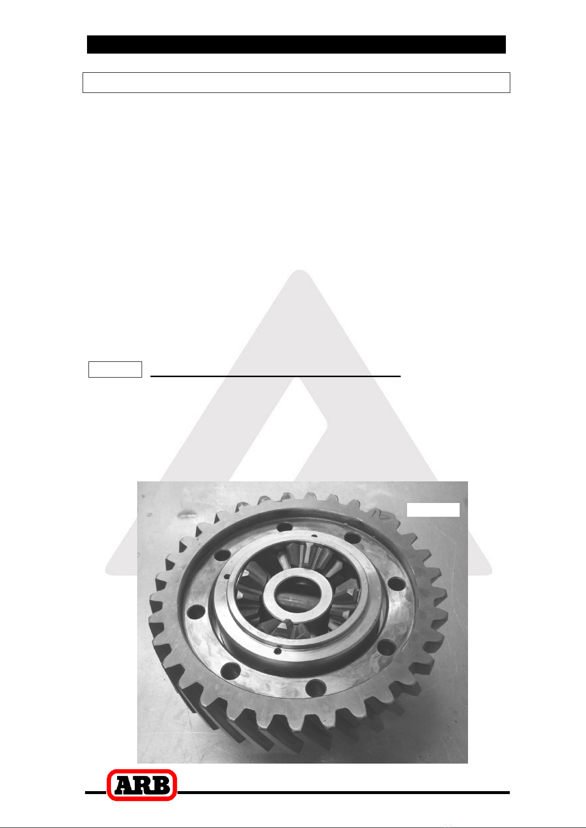
2.4 Marking the Bearing Caps
Using a pointed center punch, gently mark the bearing caps in a
way that will enable you to know which cap is ‘LEFT’ and which cap
is ‘RIGHT’, which way is ‘UP’ and which way is ‘DOWN’. (Fig.1.)
HINT : Many installers choose to make one punch mark on
the left hand side of the left hand bearing cap and one
similar punch mark on the housing at close proximity to
the cap mark. The right hand side is then designated
with two punch marks on the right hand side of the cap
and two similar punch marks on the housing.
Figure
1.

2 Removing the Existing Differential
7
2.5 Removing the Differential Carrier
Remove both adjuster nut locking tabs.
Loosen both bearing caps.
Using the appropriate adjuster nut wrench, loosen the adjuster nuts
at least half a turn.
Remove the bearing caps.
Carefully remove the differential carrier.
NOTE : The differential carrier is heavy and quite difficult to
handle when covered in oil. Take care not to drop it.
3 Installing the Air Locker
8
3.1 Re-Mounting the Ring Gear
Remove the bolts that hold the ring gear in place.
Using a plastic or copper hammer, tap in a circle around the ring
gear to separate it from the two halves of the original differential
carrier.
Cut the cable ties holding the two halves of the Air Locker together
and separate the case and flange cap.
Apply a thin film of high pressure grease to the outside diameter on
the case of the Air Locker to prevent seizing.
Thoroughly clean any thread locking compound or other foreign
matter from the holes of the ring gear, the threads of the ring gear
bolts, and the mating surfaces between the ring gear and the Air
Locker flange.
Heat the ring gear to between 80 and 100C [175 - 212F] in hot
water or in an oven to slightly expand the gear and facilitate
assembly.
NOTE : NEVER HEAT GEARS WITH A FLAME! This could
damage the hardened surface of the gear and result
in premature wear or failure.
Dry the gear and bolt holes with compressed air (if wet).
Install the ring gear onto the case of the Air Locker by aligning the
bolt holes and then gently tapping it around in a circle with a soft
mallet (Figure 2.).
Figure
2.
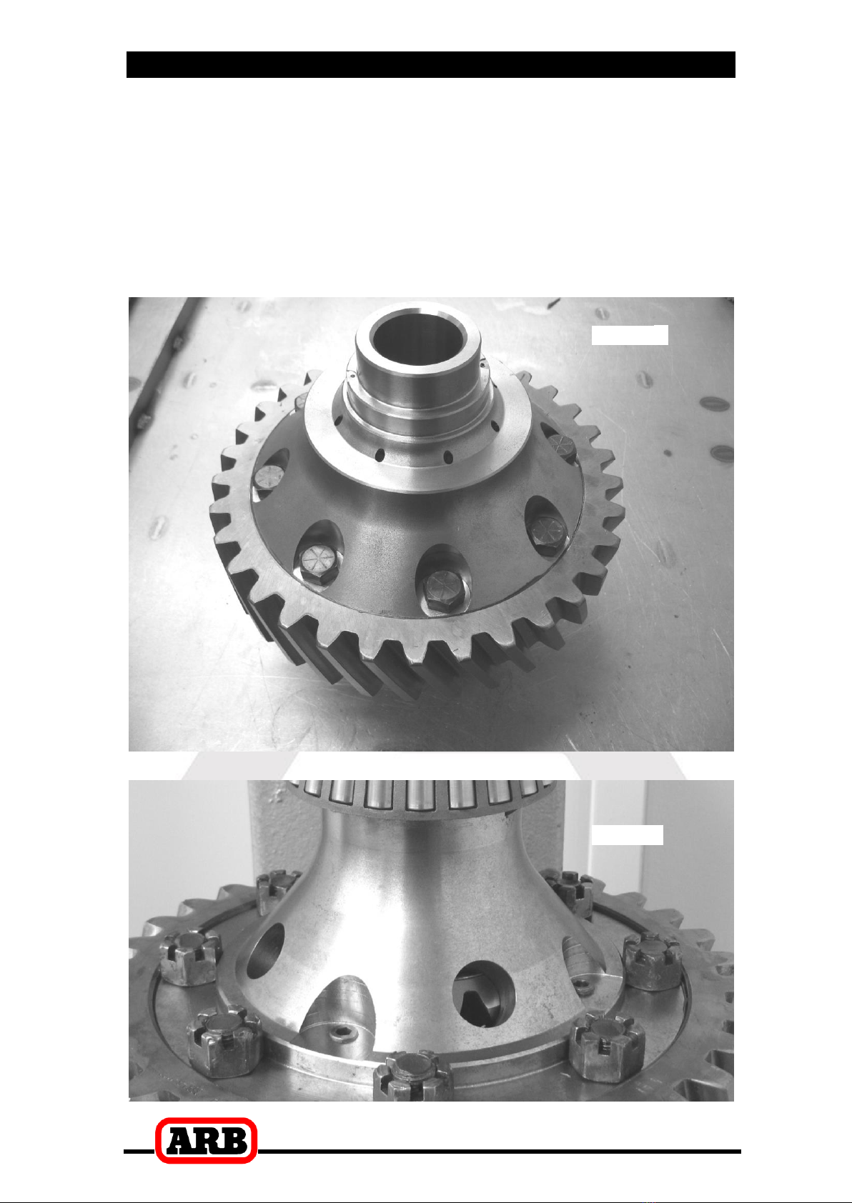
3 Installing the Air Locker
9
Apply a thin film of high pressure grease to the ring gear diameter
of the flange cap and install the flange cap into the ring gear.
Apply a thread locking compound to the thread of each ring gear
bolt before inserting into the Air Locker.
Install the nuts and tighten the ring gear bolts in a star pattern with
a torque wrench according to your vehicle manufacturer’s specified
torque (Figure 3.). The nuts will be held captive by the machined
face on the case (Figure 4.).
Figure
3.
Figure
4.
3 Installing the Air Locker
10
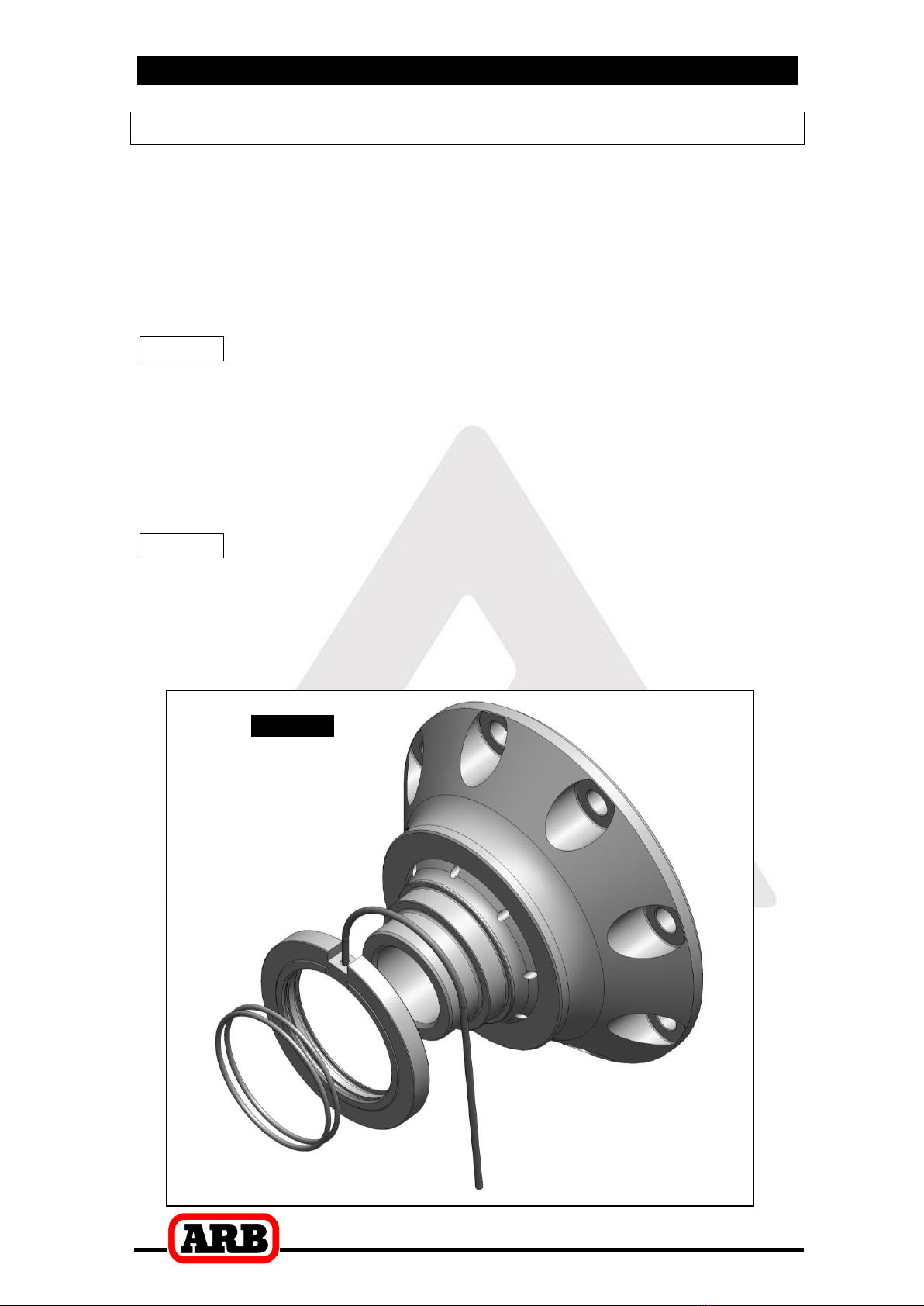
3.2 Assembling the Seal Housing
Make sure the grooves and airway of the seal housing are clean
and free from any contaminants (e.g. water, dirt, metal filings, etc.).
Inspect the seal housing O-rings (supplied) for dirt, damage or
other conditions which might cause leaks.
Generously lubricate the O-rings with oil prior to assembly, then
insert them into the grooves of the seal housing.
NOTE : When assembling the O-rings, be careful not to leave
them twisted when seated in the grooves as this could
cause excessive wear and leakage.
Lubricate the seal housing running surface on the Air Locker carrier
with oil.
Carefully install the seal housing by sliding it all of the way onto the
seal housing running surface with a gentle twisting motion.
NOTE : A twisting motion (i.e., a slight rotation while pressing
the seal housing on) will allow the O-rings to engage
gently and prevent them from twisting. Twisted
O-rings will result in pre-mature O-ring wear and oil
contamination in the air system due to the helical
shape formed by the O-ring mould line.
Figure
5.
3 Installing the Air Locker
11
3.3 Installing the Carrier Bearings
If the tapered roller bearings from the original differential carrier are
to be reused, then remove them with an automotive bearing puller
and inspect them for damage and/or wear and replace them if
necessary.
Apply a thin film of high pressure grease to both bearing journals of
the Air Locker to prevent seizing.
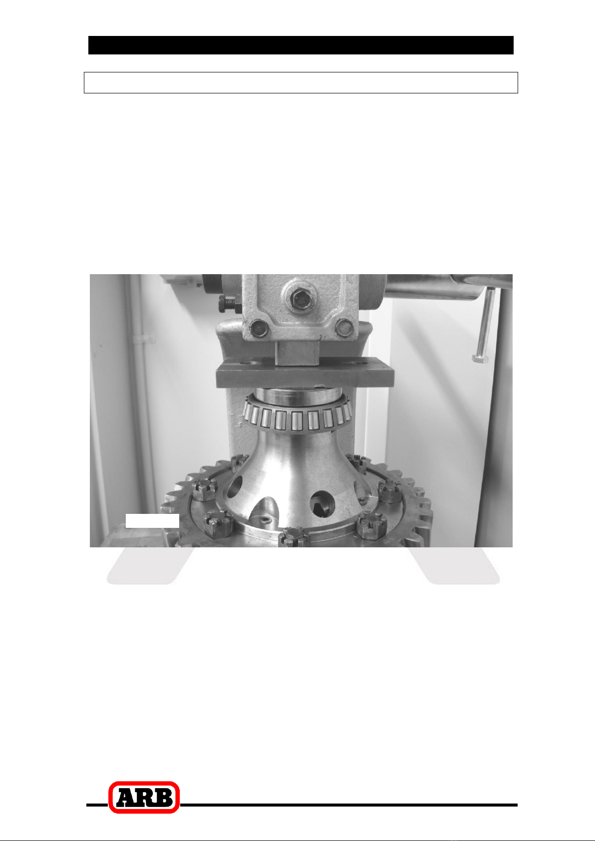
Using a bearing press or arbor press, press one of the bearing
cones onto the Air Locker bearing journal, with the seal housing in
place, until the bearing seats firmly against the bearing journal
shoulder. (As shown in Figure 6.)
Figure
6.
Invert the Air Locker and press the other tapered roller bearing
cone onto the opposite bearing journal of the differential carrier until
the bearing seats firmly against the bearing journal shoulder.

3 Installing the Air Locker
12
3.4 Drilling and Tapping the Bulkhead Port
An airline port must be drilled and tapped through the axle housing
casting to mount the bulkhead fitting into.
Cover the worm gear area with rags to protect from metal filings.
Mark a spot on the axle housing casting in the position shown in
Figure 7.
Figure
7.
Drill through the housing square to the inside surface using a
11.2mm [7/16”] drill.
Tap the hole from the outside using a ¼” NPT pipe tap.
Remove any sharp edges from the hole that may chip-off and fall
into the housing.
3 Installing the Air Locker
13
3.5 Final Air Locker Assembly
Reinstall the Air Locker into the axle housing.
Install the bearing caps oriented as they were marked before they
were removed.
Rotate the seal housing so the slot and the tube are pointing
straight out of the axle opening. Then install the seal housing
bracket with the tab locating in the slot as shown in Figure 8.
NOTE : Washers are to be left off the seal housing side
bearing cap bolts.
Figure
8.
Insert the bearing cap bolts and finger tighten. It is not necessary to
torque them down at this time.
Tighten the adjuster nuts to give the carrier bearings the required
preload.

3 Installing the Air Locker
14
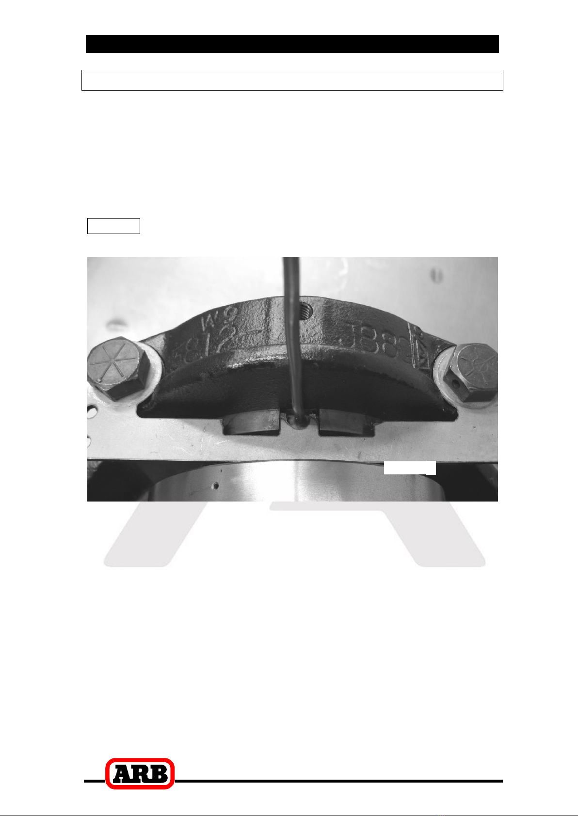
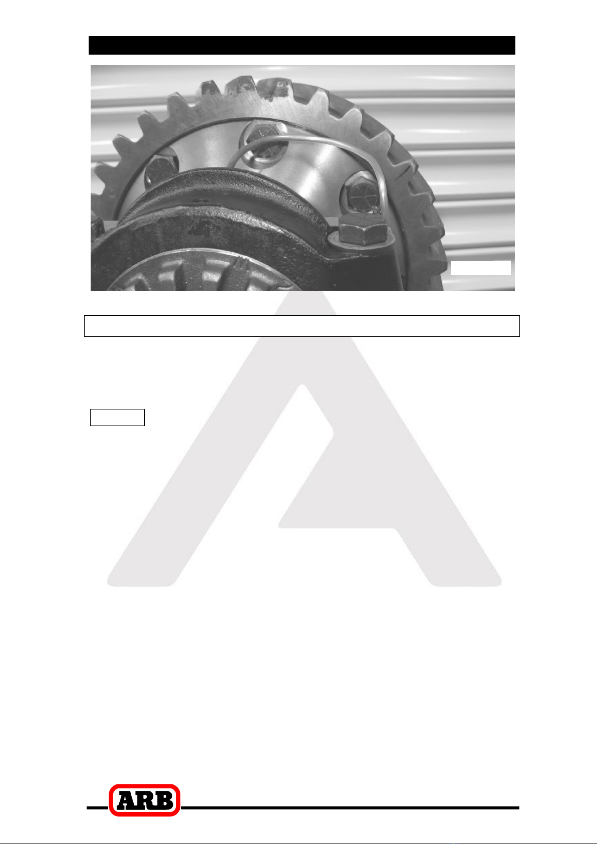
3.6 Profiling the Seal Housing Tube
Without using sharp, jagged tools such as pliers (your hands are
the best tool for this job), gently bend the seal housing tube so that
it runs in a loop beside the flange cap and out through the tapped
bulkhead port as shown in Figures 9., 10., and 11.
NOTE : It is a good idea to cable tie the tube to the seal
housing bracket to keep it from contacting anything
inside the housing.
Figure
9.
Figure
10.
3 Installing the Air Locker
15
Figure
11.
3.7 Setting Up the Bulkhead Fitting
Trim the seal housing tube that is extended through the bulkhead
port to approximately 8mm [5/16”] long using an automotive brake
line tubing cutter.
NOTE : Never use a hacksaw to cut the seal housing tube as
this will leave metal filings in the air system.
Apply thread sealant to the outside threads of the bulkhead body.
Screw the bulkhead body into the tapped hole, and lightly tighten
using a 14mm [9/16”] spanner.
Wipe the area clean of any excess thread sealant (inside and
outside of the housing).
Insert the free end of the seal housing tube into the bulkhead fitting
until it protrudes approximately 8mm [5/16”] through the other side.
From the outside of the housing, assemble one of the small O-rings
over the top of the short length of seal housing tube protruding
through the bulkhead fitting.
Install the brass spacer.
Install the second small O-ring after the spacer.
While holding the seal housing tube into the bulkhead fitting, insert
the chamfered end of the center compression nut over the
extended tube as shown in the assembly diagram (Fig. 12.), and
screw it into the bulkhead body, and tighten using Pozidriv #3
screwdriver.

3 Installing the Air Locker
16
Figure
12.
NOTE : Make sure the seal housing tube is all of the way into
the center compression nut while you are tightening
it.
NOTE : Firmly tighten the center compression nut so that a
good seal is formed around the tube.

3 Installing the Air Locker
17
3.8 Bench Testing the Air Locker
To test the Air Locker, when 620kPa [90 PSI] shop air is applied to
the seal housing tube, the Air Locker should engage.
Check all fittings and the seal housing for air leaks.
Rotate the differential carrier by turning the pinion flange whilst
applying air pressure.
NOTE : An accurate way to test for air leaks is to fit a shut-off
valve to an air pressure gauge (Available as ARB part
#ALTG01). Charge with shop air until 620 KPA [90 PSI]
is reached, shut the valve off, disconnect the air hose,
and watch to see if there is any drop in pressure. Any
gradual pressure drop indicates an air leak. (Fig.13.)
Figure
13.
If a leak is found to be present, spray a soap and water mixture
onto the bulkhead air fitting. Bubbles should appear at any leak
points.
NOTE : Do not spray this soapy mixture inside the differential.
Check that leaky fittings have been adequately tightened.
Disassemble, clean threads, and reapply thread sealant if leaking
persists.
If a leak is found at the seal housing, carefully remove and refit. Be
very careful with the O-rings and check they have not been
damaged during installation.
3.9 Reinstalling the Differential and Axles
Reinstall the differential and axles as per your vehicle
manufacturers service manual.

4 Installing the Air System
18
4.1 Mounting the Solenoid
4.1.1 Connection to an ARB Air Compressor (Fig.14.)
Remove one of the 1/8” BSP plugs from its port in the compressor
manifold.
Apply Teflon paste to the 1/8” BSP nipple on the solenoid and
insert it into the port and tighten. The solenoid should be rotated
into a position which does not obstruct any other ports on the
compressor tank.
NOTE : The coil and stem of the solenoid can be removed to
make installation easier.
NOTE : The solenoid is marked with two #1 ports. If space is
tight, a second solenoid can be “daisy-chained” off
the first one by removing the plug from the redundant
#1 port and screwing the nipple from the second
solenoid into it (Fig. 14.).
NOTE : The solenoid exhausts compressed air through the
center of the black retaining cap when the Air Locker
is disengaged. Make sure this orifice cannot be
obstructed.
Assemble the 6mm push-in fitting into the solenoid outlet port
(stamped “2”) and hand tighten.
Figure
14.
Table of contents
Other ARB Automobile Accessories manuals

ARB
ARB 3444070 User manual

ARB
ARB Air Locker RD111 User manual

ARB
ARB 1780500 User manual

ARB
ARB AIRLOCKER RD132 User manual

ARB
ARB 3432050 User manual

ARB
ARB 3434040 User manual

ARB
ARB RD121 Operating and maintenance instructions

ARB
ARB AIRLOCKER RD142 User manual

ARB
ARB INTENSITY SOLIS User manual

ARB
ARB AIRLOCKER RD109 User manual


Popular Automobile Accessories manuals by other brands

Racelogic
Racelogic Speed & Route Profiler manual

Offroad Animal
Offroad Animal PR-JGC-WK2-11-ASM0 FITTING INSTRUCTION

Whelen Engineering Company
Whelen Engineering Company SAK45 installation guide

tams elektronik
tams elektronik FCS-4 manual

RJ Power
RJ Power REV-CC3000 user guide

Code 3
Code 3 Pursuit 25 Series installation manual


