Onwa KP-32 User manual

oNm
KP.32
MARINE GPS/SBAS NAVIGATOR
L
I

,ns for
B-"_:y.r" the power supply is compatible
with the equipment.
lncorrect power supply may cause the
equipment to overheat.
The useable temperature range for the
antenna unit is -2EC to 70C; -1SC to
55C forthe disptay unit.
Use of the equipment out of those
ranges may damage the equipment.
Do not open the equipment.
Only qualified personnel should work
inside the equipment.
Do not disassemble or modify the
equipment.
Fire,electrical shock or serious injury can
result.
lmmediately turn off the power at the
switchboard if the equipment is
emitting smoke orfire.
Continued use of the equipment can
cause fire or electrical shock.Contact a
ONWA agent for service.
Use the proper fuse.
Use of a wrong fuse can damage the
equipment or cause fire.

NOTICE
Observe the following compass safe
di"t"n""" to prevent interference to a
magnetic comPass:
Standard
compass Steering
compass
DisplaY
unit 0.80 m0.55 m
Do not open the cover unless totally
f;ili;;;ith electrical circuits and
service manual.
lmproper handling can result in electrical
shock.
Turn off the power at the switchboard
Oetore beginning the installation'
Fire or electrical shock can result if the
power is left on.
Be sure that the Power suPPlY is
IJ.plii6i" *itt tlt" voltage rating of the
equiPment.
Connection of an incr','rect power supply
can cause fire or eqriPment
damage.The voltage rating of the
equipment appears on the label above
the power connector'
Use the Proper f use.
Use of a wrong fuse can damage the
equipment or cause fire'
II

IABLE OFCONTENTS
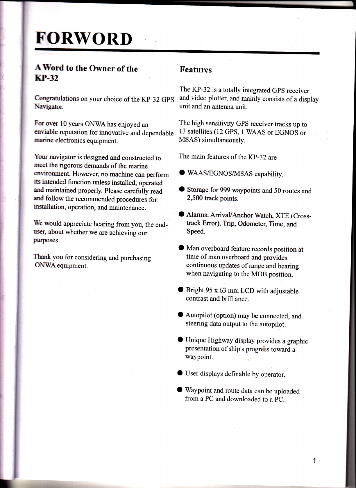
FOREWORD............ ............1
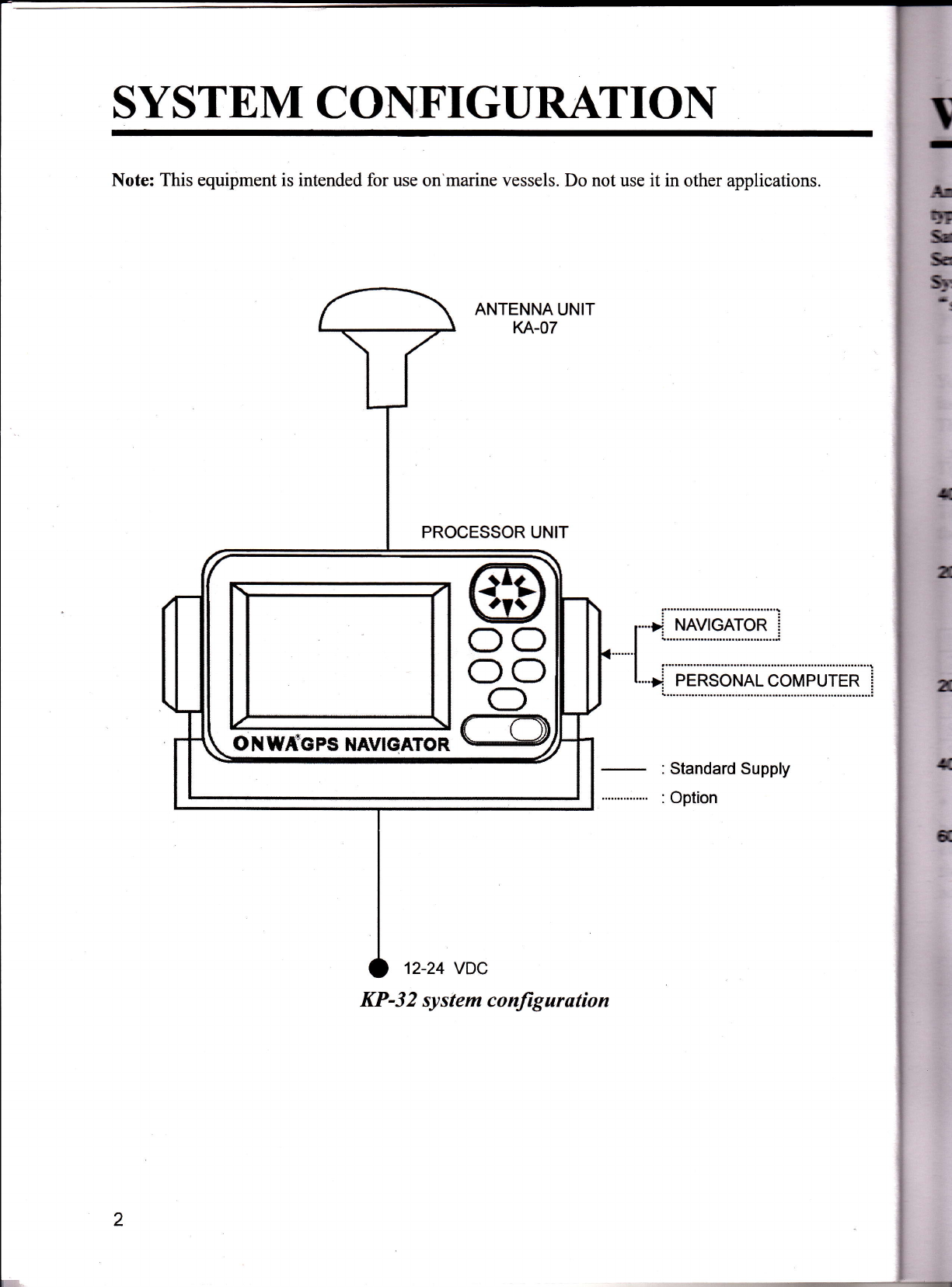
SYSTEM CONFIGIJRATION ... ... ... ...2
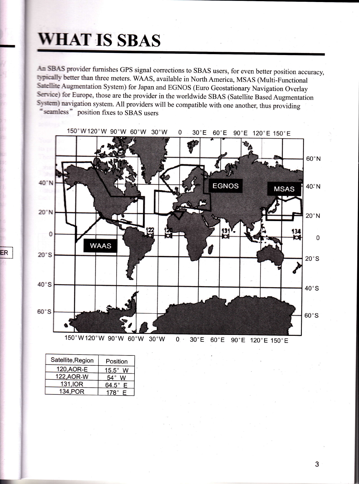
wHAr rs SBAS. ............3
1. OPERATIONAL OVERVIEW... ... ... 4
l.l Controls... ... ............4
1.2 Turning On and Offpower. ......5
1.3 Adjusting Brilliance and Contrast......5
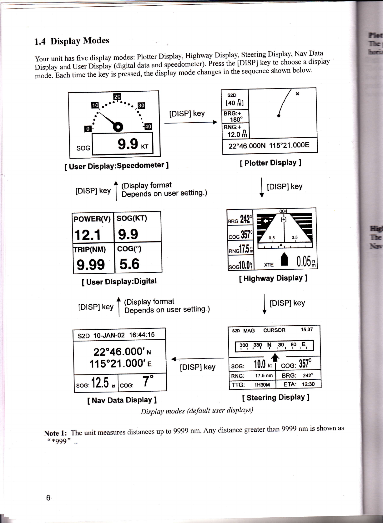
1.4 Display Modes..... ............6
1.5 Menu Overview.. ............10
1.6 Simulation Display ............1I
2. PLOTTER DISPLAY OVERVIEW...12
2.1 Choosing the Display Range... .........12
2.2 Shifting the Cursor...... .........12
2.3 Shifting the Display ............13
2.4 Centering Own Ship's position.........13
2.5 Changing Track plotting Interval
StoppingPlotting... ............13
2.6 Erasing Track...... ......14
3. WAyporNTS (MARKS)... ... ... ... ...ls
3.1 EnteringWaypoints...... ....:.15
3.2 Entering the MOB Mark... ............17
3.3 Displaying Waypoint Name... ... ... ... I g
3.4 Operations on the Waypoint List......lg
3.5 Erasing Waypoints. ......1g
3.6 Speed for Calculating Time-to-Go,
Etimated Time of Arrival... ............20
4. ROUTES... ............21
4.2 Editing Routes... ......25
4.3 Erasing Routes... ......27
5.1 Setting Destination by Cursor.........2g
5.2 Setting Destination by Waypoint......2g
5.3 Setting Route as Destination... ... ... ... 29
5.4 Setting User Waypoint as Destination... 29
5.5 Canceling Destination... ......2g
6. ALARMS...... .........30
6.1 Arrival Alarm Anchor Watch Alarm...30
6.2 XTE(Cross Track Error) Alarm... . . . . ..3 I
6.3 SpeedAlarm... .........32
6.4 Time Alarm... .........32
6.5 TripAlarm...... ..................33
6.6 Odometer Alarm.. ......33
7. OTHER FUNCTTONS... ......34
7.1 Calculating Range, Bearing, TTG and
ETA... ... ......34
7.2 Bexing Reference. ......35
7.3 Magnetic Variation ......36
7.4 Geodetic Chart System... ......36
7.5 Units of Measurement... ... ...36
7.6Time Difference (using local time),
Time Format...... ......37
7.7 cPS Setup...... ......37
7.8 User Display Setup... ... ... ...3g
7.9 Resetting Trip and Odometer,
Distances.. ......40
7. I 0 Uploading, Downloading Waypoint,
Route Data... .........40
7.ll Language... ............44
8. MAINTENANCE &
TROUBLESHOOTTNG... ... .........45
m

8.2 Displaying the Message Board""""'45
8.3 Replacing the Fuse"' """ "'46
8.4 Satellite Monitor Display"'' " "' "' "' 46
8.5 Diagnostics"' "'"'"'47
8.6 Clearing Data"""" """"47
9.1 Installation of Display Unit"'"'"' "'50
9.2 Installation of Antenna l-Init"'"'"'"'50
9.3 Wiring """ "'51
9.4 Initial Settings"' """52
APPENDX... ...54
SPECIFICATIONS. ......56
INDEX... """ "'58
,. l
w

FORWORI)
AWord to the Owner of the
IP-32
Cqmilations on your choice of the Kp-32 GpS
Nn igaior
Frover l0 years ONWAhas enjoyed an
cuviable reputation for innovative and dependable
miline electronics equipment.
Your navigator is designed and constmcted to
mt the rigorous demands of the madne
eurrironment. However, no machine can perform
is intended function unless installed, operated
rdmaintained properly. Please carefully read
rrt follow the recommended procedures for
operation, and maintenance.
IE would appreciate hearing from you, the end-
m, about whether we are achieving our
Frposes.
Thak you for considering and purchasing
ONWAequipment.
Features
The KP-32 is a totally integrated GpS receiver
and video plotter, and mainly consists of a display
unit and an antenna unit.
The high sensitivity GPS receiver tracks up to
13 satellites (12 GPS, I WAAS or EGNOS or
MSAS) simultaneously.
The main features of the KP-32 are
O TWAASiEGNO S/I\4SAS capability.
O Storage for 999 waypoints and 50 routes and
2,5W track points-
O Alarms: ArrivaUAnchor WatctU XTE (Cross-
track Error), Trip, Odometer, Time, and
Speed.
O Man overboard feature records position at
time of man overboard and provides
continuous updates ofrange and bearing
when navigating to the MOB position.
O Bright 95 x63 mm LCD with adjustable
contrast and brilliance.
O Autopilot (option) may be connected, and
steering data output to the autopilot.
O Unique Highway display provides a graphic
presentation of ship's progre'bs toward a
waypoint. ,ri
O User displays definable by operator.
O Waypoint and route datacanbe uploaded
from a PC and downloaded to a pC.
;.]{i*rei:uij

ONWfGPS NAVIGATOR
KP-3 2 sy slem conJig urotion
SYSTEM CON"FIGURATION
Note: This equipment is intended for use on'marine vessels. Do not use it in other applications.
ANTENNA UN]T
KA.O7
PROCESSOR UNIT
NAVIGATOR
PERSONALCOMPUTER i
l
:Standard Supply
: Option
12-24 VDC
2

I
I
i
-WHATIS SBAS
AG SBAS provider fumishes GPS signal corrections to SBAS users, for even better position accuracy,
ryefodb'better than three meters. V/AAS, available in North America, MSAS (Multi-Functional
Smltrite Ausmentation System) for Japan and F.GNOS (Euro Geostationary Navigation Overlay
S{n'itt) for Europe, those are the provider in the worldwide SBAS (Satellite BasedAugmentation
SlsEm) narigation system. All providers will be compatible with one another, thus p.oriding
-seamless" position fxes to SBAS users
150'W120"W 90.W 60.w 30.w 30"E 60'E
,lO"N
40"s
60's
60" N
40.'N
20" N
0
20"s
40"s
60"s
30'w 30'E 60'E g0"E 120"E 150.E
3
150" E
150"W 120"W
Satellite,Region Position
120.AOR-E 155" \/
122.AOR-W 54' \A/
131.tOR 64- 'tr
134,POR 178" F

l.
1. OPERATIONAL OVERVIEW
[.1 Controls
Press once: Zoom, centering,
or escapes from current
operation,depending on display
in use.
Press twice: Opens menu.
Chooses display mode.
Control panel
How to attach and remove the hard cover
To attach the hard cover, set it to the display unit at an angle.
To remove the hard cover, do as follows:
Cursor Pad
. Shifts cursor (cursor displayed)
and display (cursor off).
. Selects items on menus.
. Enters alphanumeric data.
Registers items on menus.
Sets/cancels destination.
Momentary press. lnscribes mark.
Long press: lnscribes MOB mark.
Momentary press: Turns power on.
\Mth the power on, press to adjust
dimmer and contrast.
Long press: Turns power off.
m
lh
I
m
r
m
m
G
t
to
TI
TI
t
m
t
*:
F
d
I
T
0t{ttA
Press at arrows
and pulltoward
you to remove.
4
A
V
\
a/
\
DIM
PWR

1.4 Display Modes
your unit has five display modes: Plotter Display, Hishyal Display,St:T-ilg Display' Nav Data
Display and User Display (digital {ata anJ tfj..a"*ier1. Fressihe [DISP] key to choose a display
mode. Each time tfr.i.i iJ plssed, the dispiay mode changes in the sequence shown below'
52D
t40 f,l /r
BRG:+
190"
RNG:+
12.0 f,
22" 46.OAAN 1 1 5"21 .000E
I Plotter DisPlaY ]
[DISP] keY
I User DisPlaY:SPeedometer ]
rDrsPl n", 1 g$:';J.t:r#er setrins )
POwER(V)
12.1 soG(Kr)
9.9
rRrP(NM)
9.99 coG(")
5.6
I User DisPlaY:Digital
rDrsPr *, 1 B#';J.t:'fl#er settins )
S2D 10-JAN-02 16:44:15
22"46.000',ru
115"21 .000'e
,on' 12.5 *coc: 7"
I Nav Data DisPlaY ]
lDlSPl key
I to'.tt *",
,^o 24I t4
i-!-
-r -r
,l \-
l\r
1,,\
.*35i
**o175;
tonl0.0l xrE I 0,05*
I Highway DisPlaY ]
I p,rrt n",
t
SzD MAG
soo 330 N 30 60 E
i-i l t -r I I I r I
"*100-f"m
RNG: 17.5 nm BRG: 212"
TTG: 1H3OM ETA: 12:N
I Steering DisPlaY ]
Display modes (default user displays)
Note l: The unit measures distances up to 9999 nm. Any distance greater than 9999 nm is shown as
" *999" ..
6
li

?
fircmadsotar
hE.GEg'
rb oum ship s hach and shows position, bearing to cursor, range to cursor,
rCE ffiing and receiver status.
kiverstafus
(See table on page 6.) Own ship mark (btinding)
+s2D
I4OflI
+<_
BRG: +
' 180"
RNG: +
12.09
+22' 46.000, N 115" 21.OOO' E<
Waypoint mark-
(Shape selectable)
Boat's track
Cursor
(Displayed six seconds.)
Cursor position
(Own ship position when
Cursor is not displayed.)
enirg
b orsof
b cursof
Range
ttrtEand SOG replace bearing to cursor and range
bqrsornrtren the cursor is ndt Oisptaye
Plotter display
lft;pfrqphy
ffiffii:x.:videsa3-Dviewofownship,sprogresstowarddestination(waypoint).
Bearing from own ship to destination
waypoint t:
Course
over
ground
,*" tt' cURSOR{_
--T-.-l
lfJ (r-
0.5 ffi
r*Tmr
1XTE
"on 110
**n $,(}*
Speed
over
ground
pfrom
ship to
,"J2,5t
Analog XJE (Cross{rack error) scale
Arrow shifts with boat,s XffEnen tne
arrow is aligned with the centerline the
boat is on course.The arrow blinks if
boat's XTE is greater than XTE scale
Direction to steer (to return to course)
Appears to right or left of centerline '
depending on direction to steer;
i : Steer right, F r Steer left.
Destination wayooint name
'CURSOR " (cursor-selected
destination) or waypoint name.
Destination waypoint
Moves fonivard as boat
nears destination.
A C (Delta Course)
The boat mark displays
Course as follows:
When no waypoint is set:
The msde is North-up and the
arrow shows boat's course.
When a waypoint is set:
The arrow shows boat,s course
towards destination.
DigitalXTE indication
(in nauticalmiles)
Range fron
own ship tc
destination
urypoint range."N" (North) is displayed instead
of the arrow when no destination is set.
Highway display
7

Steering disPlaY
ifr. rt""-ri"g dirptuy provides steering information such as ship's speed,
ETA and TTG.
bearing.
URSOR or waYPoint name)
Receiver status
Bearing reference (MAG oTTRUE)
Destination (C
dzo n,tne cuRSoR o4:32
soG: 12,5 *, tm
W goo g3o ltl s) 60 E
RNG: 0.16 nm BRG: 600
TTG: 1H30M ETA 12:3O
Bearing scale
Own ship mark
Course over ground
Bearing
Estimated Time of
Arrivalat destination
(*9:*9 shown when
ETA is over 99h59min.)
Date and time
Position in latitude
and longitude
Course over ground
Speed over ground
Range from own
ship to destination
Time-To-Go
to destination
(.9H.9M is disPlaYed
when TTG is over 99
h59min.) Steering disPlaY
Nav data disPlaY
The nav aata disitay shows receiver status, position in latitude and longitude' course
over ground, speed over ground, date and time'
8
Receiver status
SzD 10-JAN-02 16:44:15
22046.000' I
E
1 1 5" 21 .000'
I
Sfed over ground
Nav data disPlaY

p
f,drys are alailabte. digital and speedometer.
ld[sph1 shorns digital navigation data. The user may choose what data to display in one to
The fuioes of data are time, speed over ground, cross-track error, odometer distance,
h-re oTer ground- time-to-go to destination, trip distance, power source voltage, range and
rtgtrryaoin! and estimated time of arrival at destination.
POWEH(V)
12,1 soG{Kr}
9.9
rRlP(NDD
g.gg coe(")
5.6
Digital display (default display)
ryooAmeter display provides both digital and analog displays of speed over ground.
Q." E
ala at a
a
a
I
a
r
SOG 9.9 Kr
Speedometer display
I
I

1.5 Menu Overview
Most operations of your unit are carried out
through the menu- Below is a quick introduction
to how to choose a menu and change menu
settings. If you get lost in operation, press the
tMEliUl kiy toreturn to the MAIN MENU' For
yo* r"f"r"nce, a complete menu tree appears in
the Appendix.
1. Press the [MENU] key once or twice to
display the menu.
Or" i""..t Steering display, nav data display
and user disPlaY-
Two presses: Plotter display, highway
displaY.
OFF
Tr ack rec ording oPtions
1. Press the [MENU]
display the menu. key once or twice to
2. Choose SYS SETUP and then
key-
5. Press A or V to choose option desired'
6. Press the [ENT] key to register your selection'
7. Press ttre [tUfNU] key twice to close the
menu.
How to enter alPhanumeric data
In some instances it is necessary to enter
alphanumeric data. The example below shows
how to enter a time difference of -6:30, to use
local time instead of UTC time'
I MAIN
IrtE*TfiffiEI
ROUTES
PLOTTER
ALARUS
ERASE
WAAS'DGPS
CALCULATE
MENU T
HESSAGES
SATELLITE
USER DISP
GPS SETUP
SYS SETUP
ITO SETUP
TD SETUP
press the [ENT]
2. Operate the cursor pad to choose a menu and
then press the [ENT] key. For example,
choose PLOTTER and then press the [ENT]
key.
TRACK REG
INTERVAL
BRG. REF.
r,AG. VAR.
WPT NAME
TTG/ETA SPD
I PLOTTEHSETUP I
EISilnEr
0.10 nm
MAG
AUTO 816
DSP GOTO
: AUTO
TRACK MEMORY USED 1o/o
PLOTTER SETUP menu
3. Choose TIME DIFF.
4. Press the [ENT] key. A cursor circumscribes
" +" .This cursor appears whenever selected
data can be changed with the cursor pad'
I SYSTEMSETUP I
LANGUAGE :
DATUM
UNITS
flME DIFF
TIME DISP
TEST?
SIMULATOR?
EXCHANGE BATTERY?
wGs84
nm, kt
+00:00
24HOUR
SYSTEM SETUP menu
I SYSTEMSETUP T
LANGUAGE: ENGLISH
DATUM
UNITS
TIME DIFF
TIME DISP
TEST?
SIMULATOR?
EXCHANGE BATTERY?
WGS84
nm, kt
EIoo : oo
24HOUB
SYSTEM SETUP menu
TIME DIFF selected
3. Use A or Y to choose menu item' For
example, choose TRACK REC'
4. Press the IENTI key. Awindow shows the
options for the item selected. (The illustration
ai the top of the next shows the options
available for TRACK REC.)
10

rction-
)
tErn
Iws
lse
fibes
lectea
t
I11
I pdlisillnf- *-- .
) swt the cursor to the next digit.
l, r V ro diplal- u 0, -
) 6 snrf the cursor to the next digit.
lrVmdisplal-u6" .
ttf,.Lu) n send the cursor to the next digit.
m-Ihlc I r V !o displa,v "3 "
m. hil ) m cend the cursor to
nn lEs I m Y ro display ..0,,
niil FBtu [SiT] ke1-.
ilf, fusfrE FIBIUI key twice to finish.
l|f hrhtfun Disptay
m diliIillrl[mkm display- provides simulated
,'f',rmof,rhis rmit- You may set the speed
-Iy ad course manually or automatically.
fiU morb are operative you may enter marks,
rm#iqsimtriom erc.
m, lhEssfrE tl{E]\n{ key once or twice to
defiefui$ tle menu.
,3 fusne SYS SETUP and thenpress the
m{n kst.
S^ Chrc 'SIMULAIOR,, and then press the
[$(T| key'. (Note that position shown
,ilEpeads on language selected on the SyS
SETLT Irrenu. After changing the language,
ffic rtrrrc6 is cleared.)
4 The cursor is selecting MODE. press the
fE\T] ke1'. Awindow shows the choices ON
end OFF.
5 Chnose ON and then press the [ENT] liey.
6. Press the [ENT] key, use the cursor pad to
enter speed to use for the simulation, and then
press the [ENT] key.
7. Press the [ENT] key.
8. Choose course (AUTO or MAN) and then
press the [ENT] key. For manual entry of
course, press the [ENT] key, enter course with
the cursor pad, and then press the [ENT] key.
The AUTO course tracks a circular course.
Note: Course must be AUTO to set simulation
destination.
9. Press the [ENT] key, enter latitude with the
cursor pad, and then press the [ENT] key.
10. Press the [ENT] key, enter longitude, and then
press the [ENT] key.
ll. Press the [MENU] key twice.
12. Choose the PLOTTER display with the
[DISP] key. SIM appears at the upper left_
hand corner when the simulator display is
active.
SIM
lao g1 d-\ Gource traced
\ /'+- in AUTO
\--l counse
coc,
82"
SOG;
e.0 r
22' 46.000' N 115" 21.000' E
Simulator display, auto course selected
13. To turn offthe simulator display, choose OFF
at step 5 in this procedure, press the IENT]
key and then press the [MENU] key twice to
finish.
Note: If the power is tumed offwhile the
simulator display is in use, SIMULATION
MODE will turn offat the next power up.
the last digit.
SIMUI-,ITOR menu

2. PLOTTER DISPLAY OVERVIE\V
2.1 Choosing the DisPlaY Range
You may choose the display range on the plotter
and highway displays. The horizontal range in the
plotter dispiay isavailable among 0'02 (40 yd),
b.os lror yaj, o.r (202vd),a.2 g\s vd),0'5,1,2,
5, 10, 20,40,80, 160 and 320 nautical miles'
(Nautical mile is the default unit of display range'
nisptay range may also be shown in kilometers
or tt it"t. Ranges shorter than the 0'5 nm are also
shown in yards or meters on the plotter display')
The horizLntal range in the highway display is
available among 0.2,0.4,0.8, l, 2,4,8 and 16
nautical miles.
1. Press the [MENU] key.The zoom, ship
centering window appears.
SHIP TO CENTEB?
Quit?
PRESS TMENUI TO SEE
THE MAIN MENU.
Zoom, ship centering window
Note: "SHIPTO CENTER" does not appear
when the highway display mode is active'
2. ZOOMIN/OUT is selected' Press the [ENT]
key to show the zoom window'
3. Use A (increase) or V (decrease) to choose
range desired.
4. Preis the [ENT] key to close the zoom, ship
centering window.
2.2 Shifting the Cursor
Use the cursor pad to shift the cursor' The cursor
moves in the direction of the arrow or diagonal
pressed on the cursor Pad-
Cursor state and data
Cursor state determines what data is shown on
ditpluy.
Cursor turned on
C,*o. position is displayed in latitude and
longitude at the bottom of the plotter display
whin the cursor is on. The range and bearing
from own.ship to the cursor appear at the left-
hand side of the disPlaY.
ffi
hom window
r
Bearing from own
ship to cursor Cursor
Cursor position in
latitude and longitude
Range from own shiP to cursor
Plotter displaY, cursor turned on
52D
[.02fi1
4o o'
+22" 46.000' N 115" 21.000' E
12

m/
-
I
lm$e
i
i!frb
rnrcrrcd sten ttrere is no cirrsor pad
hem six seconds. Ship,s p*iiiir,
@ ryea uten the cursor is off.
Own ship's position
(Blinking)
Orf,eorerground
st@
[@a #t
S' T
/
,0fiC
> 15"
@
,7-Ot
22'6.m0. N 115" 21.000, E
SEEd Own ship's position in
Etitude and longitude
fiiM dryW, cursor turned off
ffinS the Display
ilqr c,n be shifted on the plotter display.
frc crlrsor pad to place the cursor ";;
2.5 Changing Track plottine
Interval, Stopping plotting
To trle the ship's track, the ship,s position is
stored into the memory at an inLrval of distance
Slil:ldlrg to display ranse. For distance, a
s-norter rntervar provides better reconstruction of
the track, but the storage time of the track is
reduced. When the track -"-o.y U""ot", fUf,
the oldest track is erased to make roorr, ru, tn.
latest.
1. fyesl the [MENU] key once or twice to
display the menu.
2. Choose PLOTTER.
3. Press the [ENT] key.
r PLOTTERSETUP T
,ift?[Ir";ffi
BRG. REF. : llAG
y^191vA8. : AUTo Et6
WP-T NAME : DSp GoTo
TTGIETA SpD : AUTO
TBACK ilE[,tOHy USEO 1%
?LOTTER SET(IP menu
4.The cursor is selecting TRACK REC. press
the [ENT] key to show tfre tract reclraing
method options.
I
iGusor
p""I
I
I
fiEf,
orqtd
GfiEdeE sreen- rn. airpiay,-iit, ir'rt"
fu* Wocite to cursor pad operation.
ru;H'ffifl :#,i.o;ffi.I;:;l"1lTn"
mmrh$Ea* is automaticaily.eturneJ to the
{lmilii+s@E- you can also retum it manually as
eflUoimsr
U mhEns rte [MENU] key.
1 fuCIrc .SIilP To CENTER,,
5 P@$s the pNIl key.
OFF
Thack recording method options
5. Choose OFF, I,ISTANCE oTAUTO and then
press the [ENT] key.
OFF: Track is neitirer recorded nor plotted.
This setting is useful when V", a" "iineed to
record track, for exampl., *h.n."tu.nirrg to
port.
DISTANCE: Track is recorded and plotted at
the distance interval set.
AUTO: Plotting and recording interval
changes with display range selected.
't3

6. For AUTO or OFF, go to steP 7' For
DISTANCE, enter the recording iriterval as
follows:
a) Press the [ENT] keY.
b) Use { or } to choose digit to change'
c) Use A or V to change value'
d-) Press the [ENT] key after setting the
recording interval.
7. Press the [MENU] key twice to finish'
2.6 Erasing Track
All tracks can be erased. Track cannot be restored
once erased, therefore be absolutely sure you
want to erase all track.
1. Press the [MENU] key once or twice to
display the menu.
2. Choose ERASE and then press the [ENTI key
to displaY the ERASE meilL
-ERASE-
ROUTES?
TBACK?
RESET TRIP? (6.40nm)
BESET ODO? (6.40nm)
GPS DATA?
MENU SETTINGS?
ALL BACKUP DATA?
ERASE menu
3. Choose "TRACK?' andthen press the [ENT]
key. The message shown below appears'
ERASE TRACK.
ARE YOU
YES SURE?
@
Promptfor erasure of track
4. Press { to choose YES
[ENT] keY.
5. Press the [MENU] keY
and then press the
t'wice to finish.
14

..
,ii, WAYPOIIYTS (MARKS
haring Wal,ooints
h r rr-r-Pomr wrtn the cursor
LLy-fu cursor pad to place the cursor on the
thuli"nn desir€d for a waypoint.
O fumee [f\"f] key. The ioilowing window
rqm@s_
TM wrsor is on the second line of the display.
lUrm-ls stere ]-ou may enter waypoint name,
rye ma1-consist of six alphanumeric
efum.............rcters. The number shown is the youngest
:*Sry *a1-point number. If you would rather
lMqe-rhe 'mit register the waypoint under that
ry@he4 ad you do not n..dio change mark
ffiryie or enter a comment, press the JENTI
[,cn rntce to register the waypoint anJfinish.
j[.4 ermer X,UMAN as the waypoint nam", fo.
ormple. do the following:
al Press A or V to display X.
b r Phess ) to move the cursor one place and
&eu press A or V to display A.
ct Press ) to move the cursortne place and
&en press A or V to display I.
dr Ptess ) to move the cursor one place and
ttrcn press A or V to display M.
Lrn terminolog.v- a waypoint is a
Imtion on a royage, whether it be a
mmrnnediate or destination waypoint.
itumsore 999 waypoints. Waypoints
@Ed on the plotter display three ways:
urpasitiou at own ship's position, and
& nntpoint list.
EI]'TER A NEW T'YPT NAME.
@or___a
{81:DEFAULT NAME}
QUIT: IMENUI
traypoint nome entry window
Comment (default:date/time)
TTG and ETA calculated according to
speed set at TTG/ETA SpEED on
PLOIfER menu.
Waypoint attribute edit window
4. This window is where you can choose mark
shape, enter a comment, and log the waypoint
to a route (LOG RTE?). (If you do not need to
change mark shape or enter a commen|
choose. "Exit?" and. then press the IENT] key to
finish. *LOG RTE?,, is discussed in ctrapter +.;
a) Use the cursor pad to place the cursor
under "MARK"
b) Press the [ENT] key.
c) Use A or V to choose mark desired.
e) Press ) to move the cursor one place and
, then press A or V to display A.
f) Press ) to move the cursor one place and
then press A or V to display N.
g) Press the [ENT] key. Thefoilowing window
appears.
Press V -
tl]*ff]*ltrl
;L Note: operr* I
lHl Achansesthe lXl
T sequence reversetV. L,J
E*"-E=-F}*tr
't5
NAME: XAtMAt{
24'29.310'N MARK
119"05.996,E x
i{ar r r rr A-;{'-"---""-"---1'::":
'TTG 02H00M ETA: 1Z:2i
[l@ Loc RrE?
Mark s ele ction se quence

d) Press the [ENT] key' The cursor is
selecting date/time, the default comment'
Press the [ENT] keY'
e) Enter a comment (max' 16 alphanumeric
' characters) with the cursor pad and then
press the [ENT] key' To create a space'
ih*t. trrl "utantci' character' To remove all
characters which follow the cursor' choose
the underline.
g it" cursor is on "Exit?" ' Press the BNT]
keY to finish.
Entering a waypoint at own ship position
1. Press the [MARK/MOB] key momentarily on
any display. The following window appears'
V to choose mark desired, and then press the
IENTI keY again.
A. itt cursor is selecting date/time' To change
the date/time to your o*tt "o*ttttnt' press the
IENTI key, enter a comment with the cursor
pad, and ih", pt.tt the [ENT] key again'
7. Place the cursor on "Exit?" ' Press the [ENT]
key to finish.
Entering a waypoint from the waypoint list
1. Press the [MENU] key once or twice to
displaY the menu.
2. Choose WAYPOINTS'
t. P;.* the [ENT] key to show the waypoint list
options. C-hoose LIST' (NEAREST displays
waypoints from nearest to furthest; however'
waypoints cannot be entered from this
displaY.)
5. To change mark shape, place the cursor
'MARK" Press the [ENT] keY, use
4. Press the [ENT] key' The WPTS/IvIARKS
appears.
IWPTSIMARK$
filEsHI cunson
(Llsr) r
MOB
START
WPTS/MARKS list
CURSOR: Cursor position when destination is
set with cursor.
MOB: Man overboard Position'
Sflnft Starting point when destination is
selected.
under
Aor
NAME: 001
2239.836'N MARK
115"22.059'E x
10-tAN-{12 10:25
TTG 02H0OM ETA:12:25
[@ Loc HrE?
WaYPoint attribute edrt window
2. If you want to register the waypoint-under the
number shown, and You do not need to
change mark shape or enter a comment' press
the [ENT] keY to finish'
3. To change name, choose NAME' press the
IENT] key, enter name with the cursor pad'
and then piess the IENTI key' The display
below appears.
RENAME?
Quit?
Create, rename, quit oPtions
4. Create is selected; press the [ENT] key'
16
I
M
NEAREST
Waypoint list oPtions
Other manuals for KP-32
1
Table of contents
Other Onwa Marine GPS System manuals