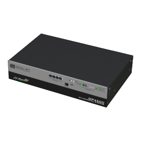
Opal-RT OP4200 User manual

OP4200 RCP/HIL SYSTEM
USER MANUAL
www.opal-rt.com

OP4200 User Manual OPAL-RT Technologies iii
SYMBOL DEFINITIONS
The following table lists the symbols used in this document to denote certain conditions:
Symbol Definition
ATTENTION: Identifies information that requires special consideration
TIP: Identifies advice or hints for the user, often in terms of performing a task
REFERENCE _ INTERNAL: Identifies an additional source of information within the bookset.
CAUTION Indicates a situation which, if not avoided, may result in equipment or work (data) on the system being
damaged or lost, or may result in the inability to properly operate the process.
Indicates a situation where users must observe precautions for handling electrostatic sensitive devices.
!
CAUTION: Indicates a potentially hazardous situation which, if not avoided, may result in minor or
moderate injury. It may also be used to alert against unsafe practices.
!
WARNING: Indicates a potentially hazardous situation which, if not avoided, could result in serious injury or
death.


OP4200 User Manual OPAL-RT Technologies 5
CONTENTS
DESCRIPTION......................................................................................................................................... 7
FEATURES .......................................................................................................................................... 7
I/O CONFIGURATIONS ........................................................................................................................ 7
SYSTEM INTERCONNECTION DETAILS ............................................................................................ 8
OP4200 HARDWARE .............................................................................................................................. 9
RECEIVING AND VERIFICATION ........................................................................................................ 9
STANDARD HARDWARE ..................................................................................................................... 9
OptiOnal Hardware .............................................................................................................................................9
HARDWARE INTERFACE .................................................................................................................. 10
Side COnneCtOrS ...............................................................................................................................................10
FRONT CONNECTORS ..................................................................................................................... 11
CASSETTES ....................................................................................................................................... 12
CaSSette ledS ................................................................................................................................................. 12
BASIC INSTALLATION ....................................................................................................................... 13
GENERAL CABLING INSTRUCTIONS .............................................................................................. 13
COnneCt tHe pOwer Cable ...............................................................................................................................13
COnneCting tHe grOund SCrew .........................................................................................................................14
COnneCting netwOrk Cable .............................................................................................................................. 14
INITIAL SETUP ................................................................................................................................... 15
dip SwitCH COnfiguratiOnS ...............................................................................................................................15
CHanging tHe ip addreSS ..................................................................................................................................16
teSting SignalS uSing tHe lOOpbaCk kit ............................................................................................................19
PIN ASSIGNMENTS .......................................................................................................................... 20
TROUBLESHOOTING HARDWARE SETUP ..................................................................................... 21
OP4200 HARDWARE - CASSETTES.................................................................................................... 23
OP4230-1 16 ANALOG OUTPUTS .................................................................................................... 23
featureS ......................................................................................................................................................23
deSCriptiOn ................................................................................................................................................ 23
SCHeMatiCS ..................................................................................................................................................23
tYpiCal appliCatiOnS ............................................................................................................................... 24
OP4240-1 16 ANALOG INPUTS ........................................................................................................ 25
featureS ......................................................................................................................................................25
deSCriptiOn ................................................................................................................................................ 25
SCHeMatiCS ..................................................................................................................................................25
OP4242-1 16 ANALOG INPUTS ........................................................................................................ 26
featureS ......................................................................................................................................................26
deSCriptiOn ............................................................................................................................................... 26
SCHeMatiCS ..................................................................................................................................................26

OP4250-1 32 DIGITAL INPUTS .......................................................................................................... 27
featureS ......................................................................................................................................................27
interfaCeS .................................................................................................................................................. 27
tYpiCal appliCatiOnS ............................................................................................................................... 28
OP4260-1 32 DIGITAL OUTPUTS ...................................................................................................... 29
featureS ......................................................................................................................................................29
Recommendations ........................................................................................................................................................ 29
OP4200 HARDWARE SPECIFICATIONS ............................................................................................. 30
OP4200 GENERAL SPECIFICATIONS .............................................................................................. 30
Op4230-1 SpeCifiCatiOnS .........................................................................................................................31
Op4240-1 SpeCifiCatiOnS .........................................................................................................................32
Op4242-1 SpeCifiCatiOnS ..........................................................................................................................33
Op4250-1 SpeCifiCatiOnS ..........................................................................................................................34
Op4260-1 SpeCifiCatiOnS ..........................................................................................................................35
LIMITED WARRANTY............................................................................................................................ 36
liMited warrantY ..................................................................................................................................... 36
return pOliCY ............................................................................................................................................ 36
eXCluSiOnS .................................................................................................................................................. 36
warrantY liMitatiOn and eXCluSiOn ..................................................................................................37
diSClaiMer Of unStated warrantieS ................................................................................................37
liMitatiOn Of liabilitY ............................................................................................................................. 37

OP4200 User Manual OPAL-RT Technologies 7
DESCRIPTION
I/O Configurations
DESCRIPTION
The OP4200 is part of the OPAL-RT line of simulation systems. It contains a SoC (system on chip)
integrating an ARM CPU and a Kintex™-7 FPGA, a high-end FPGA, signal conditioning for up to 128
I/O lines and 2 high-speed fiber-optic SFP ports. The design provides four slots for signal conditioning
cassettes.
FEATURES
• 16GB SD card.
• 1024MB DDR3L SDRAM.
• Xilinx Zynq®XC7Z030 all programmable SoC device with Dual-core ARM® Processor Cortex A9
1GHz, Kintex™-7 FPGA, 125K LUT.
• Linux-based real-time operating system.
• 4 cassettes for analog or digital I/O interfaces
• 2 high-speed communication ports
• Communication options: 2 CAN, 2 RS232, 1 Ethernet
I/O CONFIGURATIONS
The OP4200 simulator provides signal conditioning for up to 128 I/Os, which are managed from the PL
(FPGA) section of the Zynq module.
The I/O lines are routed from the Zynq board to the 4 cassettes, through the OP4200’s carrier board.
The swappable cassettes provide signal conditioning flexibility. They are factory configured and their
configuration information is processed by the system at boot time for initialization (I/O line direction,
analog module calibration coefficients, etc.). During initialization, the boot system validates that the
cassette type and position matches the I/O configuration used in the model.
Zync 7030
OP4200
JTAG Zynq 7030 Carrier Board
FPGA
CPU
I/O
CASSETTE
1
I/O
CASSETTE
3
I/O
CASSETTE
4
I/O
CASSETTE
2
SFP
SFP
RS232CAN ETH USB
SYNC
RS232CAN
Figure 1: OP4200 system architecture (standard configuration)

8 OPAL-RT Technologies OP4200 User Manual
DESCRIPTION
System Interconnection Details
SYSTEM INTERCONNECTION DETAILS
Two SFP sockets are located on the left side if the chassis to allow interconnexion with 3rd-party
devices or with other OPAL-RT chassis. These sockets are connected to the PL section of the Zynq
module and configured by the FPGA programming file (generated using OPAL-RT RT-XSG toolbox).
There are two standard modes of operation available for the SFP ports, both based on the Xilinx Aurora
communication protocol:
• Generic Aurora communication: this mode is enabled using the RT-XSG blockset’s Generic Aurora
blocks in the FPGA programming file’s Simulink model. These blocks are used to exchange
data with 3rd-party devices or with other OPAL-RT systems The data communication layer (data
packing/unpacking) must be configured by the user according to the targeted application. The
communication speed is configurable between 1 and 5 GBps and the SFP transceivers should be
selected accordingly.
• OPAL-RT MUlti-System Expansion link (MUSE)1: this mode encapsulates the Aurora protocol within
a network protocol designed by OPAL-RT for inter-system communication. The communication
speed is set to 5Gbps by default, but downgrades automatically to the speed of the other port, if
that port is used at a lower speed for 3rd party device connection.
The MUSE mode is selected in the RT-XSG block by setting the synthesis manager architecture
option to <remote>. In this mode, the unit must be connected to another OPAL-RT system that is
connected in ‘central’ mode, and it then becomes a remote expansion unit (similar to an OP4520 or
OP5607). The simulator ARM CPUs are then used only for monitoring the unit, and not during the
real-time simulation.
1 Restrictions to using MUSE with OPAL-RT Board software architecture may apply depending on your application and software configuration. Please contact
your sales representative or field application engineer to verify compatibility

OP4200 User Manual OPAL-RT Technologies 9
OP4200 Hardware
Standard Hardware
OP4200 HARDWARE
RECEIVING AND VERIFICATION
After opening the package, remove the equipment and components. Check all the items described in
“Standard Hardware” and make sure that they are undamaged.
STANDARD HARDWARE
The OP4200 simulator includes the following basic hardware:
Item Description Part Number Qty
OP4200 Hardware chassis with 4 signal conditioning cassettes 429-0101-0094 1
RJ45 cable 305cm (120”) RJ45 cable BLUE T00-0817 1
USB - Serial Cable Includes DB9M-USB A Male,
DB9, F/F, null modem mini type
Converts serial connection to USB to interface OP4200 with computer
T00-0814
T00-0994
1
1
Power Supply Desktop AC Adapter 60W 24V
pluggable terminal blocks 4 pos
T00-4387
T00-0509
1
(1)
OP5972 Power jack adapter kit for OP4200 power input 0310-0287
Auxiliary power cable Cable to connect external Vuser supply to digital output cassette from
power jack adapter (OP5972)
0113-0927 1
Screw terminal board DB37 male slim breakout board (1 per bank of 16 channels) T00-4069 1
Loopback kit Provides access to quick testing and troubleshooting:
Loopback DB37 board
Flat cable
Power cable
0126-0361
0113-0737
0113-0799
1
Table 1: Standard hardware list
Optional Hardware
Item Description Part Number
OP5970 DB37 to Spring cage adaptor 000-126-0556
OP5971 DB37 to SMB adaptor 000-126-0555
OP5973 Mechanical rackmount kit 420-0108-0003
MUSE transceiver Avago AFBR-57R5APZ
MUSE cable LC-LC multimode 850nm optical fiber

10 OPAL-RT Technologies OP4200 User Manual
OP4200 Hardware
Hardware Interface
HARDWARE INTERFACE
Side Connectors
B C D E G HF
A
Figure 1: OP4200 side connector panel
A. JTAG connector for ZYNQ programming (used in the event of lost or damaged configuration, this
feature should only be used by qualified personnel).
B. SFP (small form-factor pluggable) ports controlled from the FPGA, for high-speed communication
with other simulator FPGAs or with third-party devices (see “CONNECTIVITY” for details). Each
socket controls one communication link. SFP transceivers and fiber optic cables must be selected
according to the type and speed of the communication protocol implemented in the FPGA (OPAL-
RT MUSE link or 3rd-party device connection).
MUSE link requires specific SFP and cable:
SFP: Avago AFBR-57R5APZ
Cable: LC-LC multimode 850nm optical fiber
C. RJ45 (network connection) and USB 2.0 connector.
D. Fiber optic connectors (Rx and Tx), used to synchronize the OP4200 with other simulators.
E. Phoenix terminal power connector. Can be used with OP5972 power jack adapter kit.
F. Reset button
G. DIP switches: the position of the boot mode switches allow selection of different boot modes for the
processor. (see “DIP Switch Configurations” for detailed information)
H. Ground connector screw: attach grounding wire to nearest ground when using OP4200 in high risk
environments.
!
The OP4200 may be subject to EMI when installed in proximity to other devices
OPAL-RT strongly recommends the use of anti-static wrist straps whenever handling any electronic
device provided by OPAL-RT. Damage resulting from electrostatic charges will not be covered by the
manufacturer’s warranty.

OP4200 User Manual OPAL-RT Technologies 11
OP4200 Hardware
Front Connectors
FRONT CONNECTORS
B C D
A
Figure 2: OP4200 rear connector panels
A. Function LEDs and Power button
Press the power once to power up the unit. Press twice to shut down. The power button lights when
the unit is powered up and functioning.
There are 6 LED indicators on the housing:
NAME Color Description
STATUS Green
Yellow
Indicates that the unit is powered up and functioning properly
Indicates a system error
CONFIG Green Indicates that FPGA programming is complete.
USER Green
Yellow
User configurable to display a condition specified by the user. If undefined,
displays no status.
SYNC TX Green Lights to indicate when unit transmits a synchronization signal.
SYNC RX Green Lights to indicate when unit receives a synchronization signal.
SYNC M/S* Green
Yellow
Lights yellow (at startup) when no model is loaded. Once a model is loaded:
Indicates that the unit is in Master mode.
Indicates that the unit is in Slave mode mode (the “Use external
synchronization source” checkbox in OPAL-RT Board driver via allows the
user to make the unit a slave)
B. RS232 connectors. Allow a direct connection to the host computer to display the “OP4200 System
Configuration” IP address modification interface.
C. CAN connectors: CAN 2.0A, 2.0B, and ISO 118981-1 standard compliant
D. I/O cassettes (see “Cassettes” for more details).

12 OPAL-RT Technologies OP4200 User Manual
OP4200 Hardware
Cassettes
CASSETTES
There are 4 cassettes slots, labeled 1 to 4, in the OP4200. The OP4200 standard configuration includes
the following four cassettes:
Slot 1: OP4240-1, 16 analog inputs
Slot 2: OP4230-1, 16 analog outputs
Slot 3: OP4250-1, 32 digital inputs
Slot 4: OP4260-1, 32 digital outputs.
See the sections specific to each cassette for conditioning details.
Digital cassettes have two DB37 connectors (one for channels 00-15 and one for channels 16-31), and
analog cassettes have one DB37 connector (for channels 00-15).
Cassette LEDs
Each cassette has 4 LEDs, each used to indicate a specific status:
LED # NAME DESCRIPTION
1Status Blinking green: FPGA and hardware functioning normally.
Blinking red: FPGA not responding, not sending heartbeat signal to cassette.
Off: hardware malfunction in cassette.
2VUser1
(digital only)
Green = external Vuser present
Red = no external Vuser present
3VUser2
(digital only)
Green = Vuser present
Red = no Vuser present
4User NOT USED

OP4200 User Manual OPAL-RT Technologies 13
OP4200 Hardware
General Cabling Instructions
HARDWARE INSTALLATION
BASIC INSTALLATION
Follow this simple installation procedure. Make sure to respect proper grounding,
1. Place the OP4200 on a shelf or desktop.
2. Connect the power cable to the nearest power outlet
3. If using in high risk tests or environment, connect the ground screw as described in the
“Connecting Network Cable” section below
4. Connect the RJ45 cable from the OP4200 to a network jack.
OPAL-RT strongly recommends the use of anti-static wrist straps whenever handling any electronic
device provided by OPAL-RT. Damage resulting from electrostatic charges will not be covered by the
manufacturer’s warranty.
!
Disconnect power before servicing.
!
The OP4200 may be subjected to EMI when installed in proximity to other devices. Make sure to
connect the OP4200 to the nearest ground to prevent any EMI related damage to the simulator.
GENERAL CABLING INSTRUCTIONS
The OP4200 provides a number of connectors that each allow users a specific interaction with the
unit. Some connections are necessary to operate the OP4200, while others provide optional features
and interactions. This section presents the necessary connections first, then provides instructions for
optional connections.
Connect the Power Cable
The power cable is connected to the OP4200 using a special adaptor (OP5972).
3
1
2
POWER LED
Figure 3: Connecting the power cable
1. Press the power adapter box firmly into the phoenix connector on the OP4200
2. Insert power supply connector into adapter box, as shown.
3. Plug power cable into appropriate source (outlet).
!
Do not insert the power cord into the Vuser 24V output (square connector
on OP5972 power jack adapter). This may damage all connected devices.
Make sure to insert the power cord connector into the round connector on
the power jack adapter
Power input connector
Vuser 24V
output
connector

14 OPAL-RT Technologies OP4200 User Manual
OP4200 Hardware
General Cabling Instructions
Connecting the Ground Screw
If you are working on high risk tests or in a high risk environment, you should connect a grounding
cable from the OP4200 ground screw to ensure that it terminates securely in a ground. Proper
grounding will help to prevent electric shocks, protect the OP4200 from voltage spikes (from a variety of
causes, including lightning strikes), and provide increased immunity from EMI by lowering noise levels
and emissions.
• Select a flat braided grounding strap of adequate length (as short as possible provides best
protection), with ring terminals on each end.
• Attach one ring terminal to the ground screw on the OP4200 (shown in Figure 4).
• Attach the other ring terminal to the nearest ground source using a nut and lockwasher.
Figure 4: Connecting the OP4200 to the ground
Connecting Network Cable
Before connecting your OP4200 to your network, verify the IP address with your IT
department. You may need to change the simulator IP address to correspond to available
addresses on your network. See “Changing the IP Address” for instructions.
The OP4200 simulator offers quick, single-ended connections, through RJ45. The network cable must
only be connected to the standard network jack. DO NOT plug the network cable into any jack other
than the jack intended for that purpose.
To network
To OP4200
Figure 5: Connecting network cable

OP4200 User Manual OPAL-RT Technologies 15
OP4200 Hardware
Initial Setup
INITIAL SETUP
Although the OP4200 is configured to function right out of the package, there are a few configurations
that may be necessary (or desired) based on your network setup or according to your specific
parameters. This section deals with how to modify those parameters before you proceed to using your
OP4200.
DIP Switch Configurations
This feature should be reserved for qualified OPAL-RT personnel.
DIP switches on the OP4200 make it possible to set various boot and operation parameters.
After a Reset, the boot mode switches are read to determine the primary boot device used (default
mode is boot from SD card).
12345678
Figure 6: DIP Switch
SW # Description Functionality
1/2 Boot mode 0/1 Used in conjunction with switch #2, this selects the device to read at boot:
Boot Device Boot Mode 1 Boot Mode 0
JTAG ON ON
NAND ON OFF
QSPI OFF ON
uSD Card OFF OFF (default position)
12345678
ON = down,
Off = up
3 Console Enable Service When set to ON, RS232 port 0 is set in terminal mode
4 N/A NOT USED
5 CAN1 Termination When set to ON the 120 ohm CAN termination is enabled for CAN port 0
6 CAN2 Termination When set to ON the 120 ohm CAN termination is enabled for CAN port 1
7 N/A NOT USED
8 N/A NOT USED

16 OPAL-RT Technologies OP4200 User Manual
OP4200 Hardware
Initial Setup
Changing the IP Address
The OP4200 pre-configured with an IP address (an identifying label will be attached to the unit), but it
may conflict with your network insfrastructure; you may need to change the IP address for your OP4200.
The best way to do this is to directly connect your OP4200 to your host computer (laptop, etc.). (Be sure
to contact your IT department to obtain a valid IP address from them).
Before you begin, make sure your computer has a serial terminal program installed; you will need it to
access the “OP4200 Recovery” application. If there is no serial terminal installed, you must install one
(such as MobaXterm) to access the OP4200 configuration application.
The RS232 cable enables users to connect the OP4200 to a PC to access the IP address modification
interface. It also allows users to perform various troubleshooting or reflashing activities.
OP4200
TO PC (USB)
RS232
TO OP4200
Figure 7: Connecting the RS232 to USB cable
4. Connect the USB connector to a computer or laptop. Wait for the computer to discover the new
connection.
5. Connect the RS232 connector end to the RS-232 (port 0) connector on the OP4200
6. Install the serial terminal application (MobaXterm) on your computer:
- Using an internet browser go to MobaTek’s mobaXtem website: http://mobaxterm.mobatek.net/.
- Click on the ”Download” section.
- Select the “Home Edition” version of MobaXterm and click on “Download Now”
- Select the “Portable edition” of “MobaXterm Home edition”
- Save the file in a known location in your computer.
- Extract the contents of the zip file and double click on the extracted executable of MobaXterm
i.e.: “MobaXterm_Personal_9.4.exe” the program will start (Note that there is no need to install
anything in your computer).
7. In MobaXterm:
a. Click the Sessions button to start a new session
b. In the Session Settings window, click on the Serial Button

OP4200 User Manual OPAL-RT Technologies 17
OP4200 Hardware
Initial Setup
Figure 8: Starting a serial session in MobaXterm
c. Select the serial (COM) port to which the OP4200 is connected (it should appear automatically
in the list)
d. Set the Speed to 115200
e. Click on the “Advanced settings” tab
f. For the “Serial engine” field, select “Microcom” to have the rest of the parameters selected
automatically
g. Click OK to start the session.
If the OP4200 was already switched on before starting this process, clicking OK does not
open the OP4200 System Configuration screen. The user must press Enter (or use the
“config” command once logged into the system) to open the OP4200 System Configuration
screen.
If the OP4200 is switched off during this process, the boot console appears when the
OP4200 is switched on and then the configuration screen pops up.

18 OPAL-RT Technologies OP4200 User Manual
OP4200 Hardware
Initial Setup
8. In the OP4200 System Configuration screen (Figure 9). Select Configure Network and click OK
(Figure 9).
Figure 9: OP4200 System Configuration screen
In the next screen (Figure 10), select “2 Statically” and click OK.
Figure 10: Network Configuration screen
- Type the following information in the next screen (Figure 11): IP address, Netmask and Gateway
(your IT department should provide you with the information).
Figure 11: IP address modification screen
- Click Submit. A confirmation screen appears (Figure 12).
Figure 12: IP address change confirmation screen
Click OK to return to the main menu. Click 4 Exit and close MobaXterm.
Your OP4200 is now ready to use and can be connected to your network. Once it is connected to the
network, you should test communication by pinging the OP4200 from your computer

OP4200 User Manual OPAL-RT Technologies 19
OP4200 Hardware
Initial Setup
Testing Signals Using the Loopback Kit
NOTE The following procedure is only used for test purposes when no external source is available.
The loopback kit included in the starter kit allows users to test system signals. Connection is made easy
with a custom flat cable that matches OPAL-RT standard DB37 pin assignments.
The loopback kit allows users to test signals by connecting the output cassette to the input cassette. If
the input reads each output signal, the unit is functioning properly and is ready to be put into service.
OUTPUT
CASSETTE
LOOPBACK BOARD
INPUT
CASSETTE
To external
source
Figure 13: Connecting the loopback kit
1. Connect one end of the flat cable to the loopback board
2. Connect the loopback board to the OP4200 DB37 output cassette
3. Connect the other end (DB37 connector) of the flat cable to the OP4200 DB37 input cassette
4. When this kit is used to test digital signals, connect the Vuser (required to preserve isolation) from
the loopback board (connector end) to an external source (wire end).

20 OPAL-RT Technologies OP4200 User Manual
OP4200 Hardware
Pin Assignments
PIN ASSIGNMENTS
Conditioning cassettes come with either one (analog) or two (digital) DB37 connectors. These
connectors respect OPAL-RT’s standard DB37 pinout, as shown in the table below.
Ch. 00-15 Ch. 16-31
DB37 Module pin
assignment DB37 Module pin
assignment
1 +CH00 20 -CH00 1 +CH16 20 -CH16
1
20
00+
01+
02+
03+
04+
05+
06+
07+
08+
09+
10+
11+
12+
13+
14+
15+
-00
-01
-02
-06
-05
-04
-03
-11
-10
-09
-08
-07
-14
-13
-12
-15
19
37
Vuser Vrtn
2 +CH01 21 -CH01 2 +CH17 21 -CH17
3 +CH02 22 -CH02 3 +CH18 22 -CH18
4 +CH03 23 -CH03 4 +CH19 23 -CH19
5 +CH04 24 -CH04 5 +CH20 24 -CH20
6 +CH05 25 -CH05 6 +CH21 25 -CH21
7 +CH06 26 -CH06 7 +CH22 26 -CH22
8 +CH07 27 -CH07 8 +CH23 27 -CH23
9 +CH08 28 -CH08 9 +CH24 28 -CH24
10 +CH09 29 -CH09 10 +CH25 29 -CH25
11 +CH10 30 -CH10 11 +CH26 30 -CH26
12 +CH11 31 -CH11 12 +CH27 31 -CH27
13 +CH12 32 -CH12 13 +CH28 32 -CH28
14 +CH13 33 -CH13 14 +CH29 33 -CH29
15 +CH14 34 -CH14 15 +CH30 34 -CH30
16 +CH15 35 -CH15 16 +CH31 35 -CH31
17 36 17 36
18 Vuser 1A* 37 Vrtn 1A* 18 Vuser 2A* 37 Vrtn 2A*
19 19
Table 2: General pin assignments
Vuser and Vrtn signals are only used with digital output modules
Table of contents
Other Opal-RT Switch manuals
Popular Switch manuals by other brands

Network Technologies Incorporated
Network Technologies Incorporated SERIMUX-SECURE-x quick start guide

Dell EMC
Dell EMC N1108T-ON Getting started guide

SMC Networks
SMC Networks TigerStack 100 1000BASE-X Management guide

Emerson
Emerson ASCO 7000 Series Operator's manual

Polytron
Polytron PSC Series instruction manual

AccuAir
AccuAir e-Level installation manual

American Fibertek
American Fibertek SM24p-PoE instruction manual

Spirax Sarco
Spirax Sarco Colima Tor Series Installation and maintenance instructions

Omron
Omron D4CC - datasheet

Sygonix
Sygonix TV03 operating instructions

Siemens
Siemens SIMATIC NET SCALANCE X-300M Compact operating instructions

Motorola
Motorola WS5100 Series troubleshooting guide