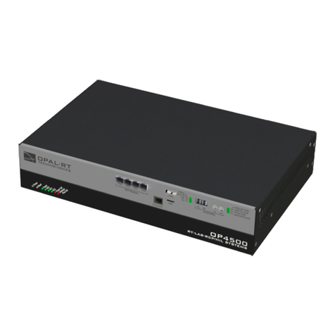
Opal-RT OP5700 User manual

OP5700
RCP/HIL/ FPGA-BASED REAL-TIME SIMULATOR
USER MANUAL
www.opal-rt.com

OP5700 User Manual OPAL-RT Technologies iii
SYMBOL DEFINITIONS
The following table lists the symbols used in this document to denote certain conditions:
Symbol Definition
ATTENTION: Identifies information that requires special consideration
TIP: Identifies advice or hints for the user, often in terms of performing a task
REFERENCE _ INTERNAL: Identifies an additional source of information within the bookset.
CAUTION Indicates a situation which, if not avoided, may result in equipment or work (data) on the system being
damaged or lost, or may result in the inability to properly operate the process.
Indicates a situation where users must observe precautions for handling electrostatic sensitive devices.
!
CAUTION: Indicates a potentially hazardous situation which, if not avoided, may result in minor or
moderate injury. It may also be used to alert against unsafe practices.
!
WARNING: Indicates a potentially hazardous situation which, if not avoided, could result in serious injury or
death.


OP5700 User Manual OPAL-RT Technologies 5
CONTENTS
RECEIVING AND VERIFICATION ........................................................................................................... 7
STANDARD HARDWARE ..................................................................................................................... 7
OptiOnal Hardware ............................................................................................................................................. 7
INTRODUCTION ...................................................................................................................................... 8
FeatUreS ....................................................................................................................................................... 8
COnFiGUratiOn OptiOnS ..........................................................................................................................10
SYSTEM INTERCONNECTION DETAILS .......................................................................................... 10
HARDWARE INTERFACE ..................................................................................................................... 11
FRONT CONNECTORS ..................................................................................................................... 11
REAR CONNECTORS ........................................................................................................................ 13
INSTALLATION...................................................................................................................................... 14
BASIC INSTALLATION ....................................................................................................................... 14
CABLING INSTRUCTIONS ................................................................................................................ 14
COnneCtinG rJ45 MOnitOrinG CaBleS ................................................................................................14
COnneCt Mini BnC tO BnC........................................................................................................................ 15
COnneCt tHe USBa tO USBB CaBle .......................................................................................................16
COnneCtinG tHe GrOUnd SCrew .........................................................................................................16
COnneCt tHe lOOpBaCK Kit ....................................................................................................................17
COnneCt tHe SCrew terMinal .............................................................................................................. 18
COnneCt tHe OptiCal FiBer CaBle ......................................................................................................18
COnneCtinG netwOrK CaBleS .............................................................................................................. 19
I/O CONFIGURATIONS ......................................................................................................................... 20
DB37F CONNECTORS ...................................................................................................................... 20
PIN ASSIGNMENTS .......................................................................................................................... 22
SPECIFICATIONS.................................................................................................................................. 23
OP5700 SPECIFICATIONS ................................................................................................................ 23
LIMITED WARRANTY............................................................................................................................ 24
liMited warrantY .....................................................................................................................................24
retUrn pOliCY ............................................................................................................................................24
eXClUSiOnS ..................................................................................................................................................24
warrantY liMitatiOn and eXClUSiOn ..................................................................................................25
diSClaiMer OF UnStated warrantieS ................................................................................................25
liMitatiOn OF liaBilitY .............................................................................................................................25


OP5700 User Manual OPAL-RT Technologies 7
Receiving and Verification
Standard Hardware
RECEIVING AND VERIFICATION
After opening the package, remove the equipment and components. Make sure that all the items
described in “Standard Hardware” are actually in the box and are undamaged.
STANDARD HARDWARE
The OP5700 real-time simulator includes the following basic hardware:
Item Description Part Number Qty
OP5700 Hardware chassis with real-time computer and FPGA 1
System integration
binder
RT-LAB or HYPERSIM software CD
O/S CD
Delivery CD (test model(s), system documentation, software licenses,
hardware documentation, additional software)
N/A 1
BNC to mini BNC
cables
2 m (6 ft 6”) adapter cables for mini-BNC to BNC. 75 Ohms simplex T00-0719 4
RJ45 cables (5) 61cm (24”) RJ45 cables BLACK
61cm (24”) RJ45 cables GREEN
61cm (24”) RJ45 cables RED
61cm (24”) RJ45 cables WHITE
305cm (120”) RJ45 cable BLUE
T00-0723
T00-0726
T00-0725
T00-0724
T00-0817
5
Power cable 1.83 m (6’) power cord, black (10A 125V) (cable varies according to
destination country)
T00-0833 1
Screw terminal board DB37 male slim breakout board (1 per bank of 16 channels) T00-4069 1
Loopback kit Provides access to quick testing and troubleshooting:
Loopback DB37 board
Flat cable
Power cable
126-0361
113-0737
113-0799
1
USBA to USBB cable 1.83m (6 ft) black USB 2.0 T00-0850 1
Screws, rubber feet Extra parts, if needed N/A
Table 1: Standard hardware list
Optional Hardware
Item Description Part Number
MUSE transceiver Avago AFBR-57R5APZ T00-0315
MUSE cable LC-LC multimode 850nm optical fiber T00-0782

8 OPAL-RT Technologies OP5700 User Manual
Introduction
Standard Hardware
INTRODUCTION
The OP5700 is a complete simulation system. It contains a powerful target computer, a high-end
reconfigurable FPGA, signal conditioning for up to 256 I/O lines and 16 high-speed fiber-optic SFP
ports. The design makes it easy to use with standard connectors (DB37, RJ45 and mini-BNC) without
the need for input/output adaptors and allows quick connections for monitoring I/O signals. It is
designed to be used either as a desktop, shelf top, or mounted in a standard 19’’ rack.
The front of the chassis provides access to monitoring interfaces and connectors and the SFP sockets,
while the back of the chassis provides access to the target computer’s standard connectors, I/O
connectors, power cable and main power switch.
Inside, the main housing is divided into two sections, each with a specific purpose:
FEATURES
The lower part of the chassis contains the target computer that can be added to a network of simulators
or can run standalone. The target computer, used to run simulations built with OPAL-RT’s RT-LAB or
HYPERSIM tools, includes the following features:
• ATX motherboard
• Linux-based real-time operating system
• Intel® Xeon® E5 CPU with 4, 8, 16 and 32 processor cores, up to 3.2GHz
• 10MB Cache Memory per 4 cores
• up to 32GB of DRAM,
• 512GB SSD disk,
• 6 PCIe slots1, used to connect the internal FPGA board and PCIe or PCI third party I/O and
communication cards.
The upper section contains the FPGA and the I/O conditioning modules. The main features include:
• Xilinx® Virtex®7 FPGA programmable from the target computer via PCIe. The FPGA is used to
execute models designed with the OPAL-RT RT-XSG tool, manage the I/O lines and execute
embedded FPGA-based simulations. It exchanges data with the real-time simulations running on
the target computer CPUs via the PCIe link.
• Flat carrier board capable of connecting any combination of up to 8 digital and analog conditioning
modules. Each module controls 16 or 32 lines for a total of up to 256 I/0 lines.
• 16 SFP ports for high speed communication with other FPGA-based systems or with external
devices.
The standard communication protocols available with the OP5707 are based on Xilinx® Aurora (1
to 5 Gbps). Other protocols, such as the Gigabit Ethernet, can also be implemented.
These SFP ports can be used to expand the simulator’s I/O capability using OPAL-RT’s MUlti-
System Expansion link (MUSE)2: each port can be connected to one OPAL-RT remote I/O unit
(OP4520, OP5607 or OP4200), effectively increasing the simulator I/O capability to a maximum of
4096 channels. SFP ports not used for MUSE remain compatible with the legacy Generic Aurora
link. The MUSE link is compatible with OPAL-RT boards I/O management architecture.
1 The CPU configuration and the use of riser boards for PCI cards may limit the number of available slots, as described in the Hardware configuration section
2 Restrictions to using MUSE with OPAL-RT board software architecture may apply depending on your application and software configuration. Please contact
your sales representative or field application engineer to verify compatibility

OP5700 User Manual OPAL-RT Technologies 9
Introduction
Standard Hardware
The figure below illustrates the simulator architecture.
Signal conditioning
modules
Carrier Board
Upper section
interfaces
Lower section
target computer
Figure 1: OP5700 simulator architecture
!
The image shown above is used to illustrate the layered and exible product architecture. Customers
should not open the chassis unless under the strick guidance of Technical Support.

10 OPAL-RT Technologies OP5700 User Manual
Introduction
System Interconnection Details
CONFIGURATION OPTIONS
The OP5700 is available in a number of CPU configurations that are factory configured according to the
customer’s processing requirement.
Product Configuration Description
OP5707-4 OP5700 RCP/HIL Virtex7 FPGA-based Real-Time Simulator - 4 cores (5U, Xeon E5, 4 Cores, 3.0 GHz,
10M, 16GB, 512GB SSD)
OP5707-8 OP5700 RCP/HIL Virtex7 FPGA-based Real-Time Simulator - 8 cores (5U, Xeon E5, 8 Cores, 3.2 GHz,
20M, 16GB, 512GB SSD)
OP5707-16 OP5700 RCP/HIL Virtex7 FPGA-based Real-Time Simulator - 16 cores (5U, Xeon E5, 2x8 Cores, 3.2
GHz, 2x20M, 2x16GB, 512GB SSD)
OP5707-32 OP5700 RCP/HIL Virtex7 FPGA-based Real-Time Simulator - 32 cores (5U, Xeon E5, 2x16 Cores, 2.3
GHz, 2x40M, 2x16GB, 512GB SSD)
The OP5700 is built with the same FPGA and I/O architecture as the OP5607 I/O expansion
chassis (OP5600 family of products), therefore the FPGA programming files (bitstreams)
are fully compatible.
SYSTEM INTERCONNECTION DETAILS
There are two standard modes of operation available for the SFP ports, both based on the Xilinx
Aurora communication protocol:
Generic Aurora communication: this mode is enabled using the RT-XSG blockset’s Generic Aurora
blocks in the FPGA programming file’s Simulink model. These blocks are used to exchange data
with 3rd-party devices or with other OPAL-RT systems The data communication layer (data packing/
unpacking) must be configured by the user according to the targeted application. The communication
speed is configurable between 1 and 5 GBps and the SFP transceivers should be selected accordingly.
OPAL-RT MUlti-System Expansion link (MUSE): this mode encapsulates the Aurora protocol within a
network protocol designed by OPAL-RT for inter-system communication. The communication speed
is set to 5Gbps by default, but downgrades automatically to the speed of the other port, if that port is
used at a lower speed for 3rd party device connection.
The MUSE mode is selected in the RT-XSG block by setting the synthesis manager architecture option
to <remote>. In this mode, the unit must be connected to another OPAL-RT system that is connected
in ‘central’ mode, and it then becomes a remote expansion unit (similar to an OP4520 or OP4200).

OP5700 User Manual OPAL-RT Technologies 11
Hardware Interface
Front Connectors
HARDWARE INTERFACE
FRONT CONNECTORS
A
G
D
CB E
F
Figure 2: OP5700 front panel
A. RJ45 connector panels provide connections to monitor signals from mezzanine I/O boards.
Each connector is linked to front and back mezzanines on the carrier board. Analog mezzanines
(channels 0-15) will use only the first column of connectors. Digital mezzanines will use both
columns (channels 0-15 in the first column and channels 16-31 on the second column of
connectors). See the “Pin Assignments” for more detailed information.
B. 16 SFP (small form-factor pluggable) ports controlled from the FPGA, for high-speed
communication with other simulator FPGAs or with third-party devices. Each socket controls one
communication link. SFP transceivers and optical fiber cables must be selected according to the
type and speed of the communication protocol implemented in the FPGA.
MUSE link requires specific SFP and cable:
SFP transceiver: Avago AFBR-57R5APZ
Cable: LC-LC multimode 850nm optical fiber
The LEDs (light pipes) associated to the selected channel will light to indicate the channel is
selected. LEDs are arrow-shaped to indicate the channels to which they are associated. The LED
upward arrow points to top channel, the downward arrow points to bottom channel (see below):

12 OPAL-RT Technologies OP5700 User Manual
Hardware Interface
Front Connectors
LED Color Description
CH01
CH00
Green ON = SFP transceiver is inserted
OFF = no SFP transceiver is present
BLINK = channel active
Green ON = SFP transceiver is inserted
OFF = no SFP transceiver is present
BLINK = channel active
Red OFF = connection okay
ON = transmission fault
BLINK = reception loss
Red OFF = connection okay
ON = transmission fault
BLINK = reception loss
C. SYNCHRO: synchronization connectors (fiber optic and audio) and a series of four LEDs on the
front panel display the device status
LED Power On After Load & During
Execution
After Reset
Tx OFF GREEN** OFF
Rx OFF GREEN** OFF
M/S Default* ORANGE = Slave GREEN
PWR GREEN GREEN GREEN
Table 2: OP5700 SYNCHRO LEDs
*The color of the LED on power on depends on the default FPGA configuration: when the FPGA
board is programmed in slave synchronization mode, the LED will be orange; when it is programmed
in master mode, the LED will be green.
**Tx and Rx provide synchronization information. When transmitting the synchronization signal, the
Tx LED will be green. When receiving the synchronization signal, the Rx LED will be green.
D. USB connector for JTAG programming (used in the event of lost or damaged FPGA configuration
E. Monitoring RJ45 connectors with mini-BNC terminals for monitoring: RJ45 cables connect from a
channel on an RJ45 panel (A) to one of four RJ45 monitoring connectors (E). Mini-BNC connectors
allow for quick cable connections to monitoring devices (such as an oscilloscope). See “Installation”
for details.
F. Target computer monitoring interface. Two push buttons include POWER in top position to start the
Target computer and RESET in the bottom position to reset the Target computer. There are 6 LED
indicators:
LED NAME Description
Green Power On indicates that the unit is powered up.
Green HDD On indicates that the hard disk drive is operating.
Green NIC1 On indicates that network port 1 is in use.
Green NIC2 On indicates that network port 2 is in use.
Red Power Fail On indicates a power fault.
Red Overheat/Fan Fail On indicates either that unit has overheated or a fan fault.
G. Optional PCI or PCIe connector slots. By default, these spaces will be covered by blank plates if
there are no optional PCI or PCIe boards. If there are boards installed, the spaces will give access
to the card connectors.

OP5700 User Manual OPAL-RT Technologies 13
Hardware Interface
Rear Connectors
REAR CONNECTORS
A
D
C
B
EF
Figure 3: OP5700 rear connector panels
A. DB37F I/O connectors (see “Table 3: Pin Assignments” for more details). Figure 13 illustrates the
links between the mezzanines and the DB37 I/O connectors
B. Power reset and +5/+12 V power source connector (for tests)
- Pushbutton reset after 4A overcurrent shutdown
- Red LED indicates fault, green LED indicates nominal function
- Microfit connector for 5V or 12V power allows users to test whether I/Os are functioning. Each
voltage has its own ground reference. Caution: these power sources are not isolated.
C. Ground screw. The OP5700 may be subjected to EMI when installed in proximity to other devices.
Make sure to connect the OP5700 ground to the rack to prevent any EMI related damage to the
simulator (see Figure 5)
D. Power connector and power On/Off switch.
E. Standard computer connectors (left to right): mouse and keyboard, USB ports, monitor, network
ports (see Figure 12).
F. Low-profile PCIe slots3. These slots give access to five of the six PCIe slots. The sixth slot is
reserved for internal connection of the Virtex7 FPGA board.
Refer to the system Description document received with your simulator for more detailed
configuration.
- OP5707-4 and OP5707-8 configurations only use one CPU, and can only manage five PCIe
slots, leaving 4 slots available for third-party I/O or communication boards.
3 High-profile PCIe boards or PCI boards must be installed in the front bays of the chassis, and connected to the motherboard using riser boards.
Since each riser uses one PCIe slot of the motherboard, the number of slots available at the back of the chassis is reduced. Each riser board can connect two
PCI cards.

14 OPAL-RT Technologies OP5700 User Manual
Installation
Cabling Instructions
INSTALLATION
BASIC INSTALLATION
Follow this simple installation procedure. Make sure to respect proper grounding,
1. Place the OP5700 on a shelf, desktop, or install in a traditional rack
2. Connect the power cable to the nearest power outlet
3. Connect the ground screw as described in the “CONNECTING THE GROUND SCREW” section
below
4. Connect the blue RJ45 cable to the Ethernet port on the OP5700 and connect to the same network
used by the host PC. Refer to the “Cabling Instructions” and the System Description document
delivered with your simulator to locate the connector to be used.
OPAL-RT strongly recommends the use of anti-static wrist straps whenever handling any electronic
device provided by OPAL-RT. Damage resulting from electrostatic charges will not be covered by the
manufacturer’s warranty.
!
Disconnect power before servicing.
!
The OP5700 may be subjected to EMI when installed in proximity to other devices. Make sure to
connect the OP5700 ground to the rack to prevent any EMI related damage to the simulator.
CABLING INSTRUCTIONS
CONNECTING RJ45 MONITORING CABLES
The OP5700 simulator offers quick, single-ended connections, through RJ45 and mini BNC connectors,
to any monitoring device (i.e. oscilloscope, etc.). These mini-BNC jacks let you monitor 4 channels
individually. Simply follow these instructions (as illustrated in Figure 5):
CAUTION
The monitoring board has a gain of 0.1 to allow a broader range of signals to be read.
Oscilloscopes must be adjusted with a gain of 10 to compensate and ensure accurate
readings.
Only connect RJ45 cables from upper section (A) monitoring jacks to lower section monitoring
panel (B, as shown). Connecting any other cable or device may result in damage to the
equipment.

OP5700 User Manual OPAL-RT Technologies 15
Installation
Cabling Instructions
A
B C
Figure 5: How to connect RJ45 cables for monitoring
A. Connect one end of the RJ45 cable to the desired channels (A). See for RJ45 connector pinouts
B. Connect the other end of the RJ45 cable to the monitoring connector (B)
C. Connect BNC cable connectors as shown in Figure 6. These are labeled A, B, C, D and each
connector represents a channel. Using the image as an example, the connectors represent
channels in the following order; A = channel 28, B = channel 29, C = channel 30 D = channel 31.
CONNECT MINI BNC TO BNC
These cables establish connections between OPAL-RT hardware and external monitoring devices.
Individual channel
monitoring
To external
monitoring device
From simulator
channel bank
CH 1
MENU
MATH
MENU
CH 2
MENU
HORIZ
MENU
SET TO
ZERO
TRIG
MENU
SET TO
50%
FORCE
TRIG
TRIG
VIEW
PRINT
REF
MENU
RUN/
STOP
SINGLE
SEQ
AUTORANGE SAVE/RECALL MEASURE ACQUIRE HELP
UTILITY CURSOR DISPLAY DEFAULT SETUP
SAVE
AUTOSET
Figure 6: Connecting BNC monitoring cables
Connect a mini-BNC cable to each jack (C) and connect the other end of the cable to the desired
monitoring device.

16 OPAL-RT Technologies OP5700 User Manual
Installation
Cabling Instructions
CONNECT THE USBA TO USBB CABLE
The USB(A)-USB(B) cable provides the connection required to flash the FPGA using the JTAG port,
when programming has been lost or damaged. Contact Technical Support for all FPGA programming
issues.
Connect one end to a Windows PC USB port and the other end to the USB JTAG port on the OPAL-RT
simulator, then follow the technical support representative’s instructions to flash the FPGA.
Windows PC
USB Ports
Simulator USB
JTAG Port
Figure 7: Connecting USB cable for FPGA programming
CONNECTING THE GROUND SCREW
You must connect a grounding cable from the OP5700 ground screw to ensure that it terminates
securely in a ground. Proper grounding will help to prevent electric shocks, protect the OP5700 from
voltage spikes (from a variety of causes, including lightning strikes), and provide increased immunity
from EMI by lowering noise levels and emissions.
• Select a flat braided grounding strap of adequate length (as short as possible provides best
protection), with ring terminals on each end.
• Attach one ring terminal to the ground screw on the OP5700 (shown in Figure 8).
• Attach the other ring terminal to the rack using a nut and lockwasher.
Figure 8: Connecting the OP5700 to the ground

OP5700 User Manual OPAL-RT Technologies 17
Installation
Cabling Instructions
CONNECT THE LOOPBACK KIT
NOTE The following procedure is only used for test purposes when no external source is available.
The loopback kit included in the starter kit allows users to test system signals. Connection is made easy
with a custom flat cable that matches OPAL-RT standard DB37 pin assignments.
• Connect one end of the flat cable to the loopback board
• Connect the loopback board to the simulator DB37 Output signal
• Connect the other end (DB37 connector) of the flat cable to the simulator DB37 Input signal
• Connect the VUser (required to preserve isolation) from the loopback board to the OP5700.
SIMULATOR
OUTPUT
LOOPBACK BOARD
SIMULATOR
INPUT
To OP5xxx
series
simulator
OP5700 series simulator
(not isolated)
Figure 9: Connecting the loopback kit
Although some boards do provide a power source, using that would compromise the
isolation. OPAL-RT recommends using external power source: the user must connect the
power wires (provided) to either a 5 or 12 V power source. Make sure that the Vuser source
switch on the loopback board is set to “External”.

18 OPAL-RT Technologies OP5700 User Manual
Installation
Cabling Instructions
CONNECT THE SCREW TERMINAL
The breakout board provided allows users to access each pin of the DB37 separately through the screw
terminals. Simply insert the breakout board DB37 connector onto the desired DB37 connector on the
simulator.
OPAL-RT simulator
DB37 connectors Screw terminal
Figure 10: Connecting the screw terminal board
Refer to the simulator or board user manual for exact pin assignments
CONNECT THE OPTICAL FIBER CABLE
The optical fiber cable is used to establish synchronization connections between simulators (as shown
below) .
Figure 11: Connecting synchronization cables

OP5700 User Manual OPAL-RT Technologies 19
Installation
Cabling Instructions
CONNECTING NETWORK CABLES
The network cable must only be connected to the standard computer connector network jack. DO NOT
connect the network cable in any jack other than the jack intended for that purpose.
To network
To simulator
Figure 12: Connecting network cables
See the System Integration document for information about the active port.

20 OPAL-RT Technologies OP5700 User Manual
I/O Configurations
DB37F Connectors
I/O CONFIGURATIONS
The OP5700 simulator provides signal conditioning for up to 256 I/Os, which are managed from the
FPGA module and are accessible via DB37 and RJ45 connectors in the back and front of the chassis.
I/O lines are routed through a carrier board (inside the chassis) that can accept up to 8 signal
conditioning modules, which provides greater signal conditioning flexibility. The conditioning modules
follow a proprietary form factor, called Type B mezzanines. A range of mezzanines are available for
analog and digital conditioning.
Mezzanines are detected at power up and information is processed by th FPGA for verification and
initialization (I/O line direction, analog module calibration coefficients, etc.). Then, mezzanines are
made available to the CPU simulation to detect improper configuration or hardware failure.
DB37F CONNECTORS
There are 4 groups of mezzanines, labeled 1 to 4; each pair (A & B) is linked to four female DB37
connectors (I/Os) on the back of the chassis:
The first two connectors (left to right) represent channels from Group B, which are linked to the
conditioned channels from the rear mezzanine. The last two connectors (left to right) represent
channels from Group A, which are linked to the conditioned channels from the front mezzanine.
DB37 connector panel
Signal out
from OP5700
to monitoring
(via BNC)
RJ45 Connector Panel
Group 1
GROUP B
Signal in
from device
to OP5700
Figure 13: DB37 connection to analog mezzanines
Other manuals for OP5700
1
Table of contents
Other Opal-RT Switch manuals