Opengear 8100 User manual

QUICK START GUIDE
CONSOLE MANAGER 8100
Includes Models: CM8116, CM8132, CM8148 ,CM8148-10G, CM8196-10G, DDC
1

REGISTER
This Quick Start Guide covers basic installation and configuration of the CM8100. For detailed guidance,
consult the Console Manager User Guide: https://opengear.com/support/documentation/.
Register your product: https://opengear.com/product-registration
When you register, you:
lActivate your warranty.
lGet notified when firmware updates are released: https://opengear.com/support/device-updates/
WHAT'S IN THE BOX
CM8100 Device
Figure: CM8100 model
2

CM8148-10G Device
Figure: CM8148-10G
3

Device Variations
Dual DC Power Supply (DDC)
DDC options have a dual DC power supply.
10GEthernet
10Gmodels have network interfaces NET1 (10G SFP+), NET2 (10GSFP+) and NET3 (1GCopper).
4

Kit Contents
Note: Contents may be different from those pictured due to region or supplier.
Label Item Quantity Notes
CM8100 device 1
1 IECpower cables or DDC terminals (optional) 2 Region-specific
2 Rack mount screw kit 1
3 CM8100 rack ears 2
4RJ45 to DB9F rollover serial adapter 1Part number 319018
5 CAT5e RJ45 UTPstraight cable - 5ft/1.5m 1 Part number 440016
Table: List of contents
5

HARDWARE INSTALLATION
Figure: Network interfaces for CM8100
Step 1. Connect Network Interfaces
Connect the device to a local network using any of the available
physical network interfaces. All interfaces will receive a dynamic
address via DHCPand DHCPv6.
Additionally, the device can be accessed from a computer or local
network via NET1 with a static IPv4 address as shown in Table:
Default static interface connection.
Model Interface Static Address
1GbEthernet NET1 192.168.0.1/24
10GbEthernet NET3 192.168.0.1/24
Table: Default static interface connection
Firewall Zone Network Interfaces
WAN NET1
LAN NET2
Table: Default firewall zones for interfaces
Step 2. Connect Serial Devices
Connect managed devices to the serial interfaces on the front of the unit.
Step 3. Connect USB Devices
USBserial devices can be connected to the USB3 slots of the unit if required.
6

Step 4. Connect The Power
AC
DDC
Figure: AC and DDC Dual power supply connectors.
AC only: Connect the power cable to the rear of the unit.
A second power cable can be connected if redundancy
is required. The power cables can be connected in any
order.
OR
DDC option: Connect the DDC terminals to the DC
power cable (not supplied) and plug the DDC terminals
into the rear of the unit.
LEDPowerStatus Indicator
Figure: Power supply has redundancy Figure: Power supply does not have redundancy
7

ACCESS THE DEVICE
Step 1. Log in via the Web UI
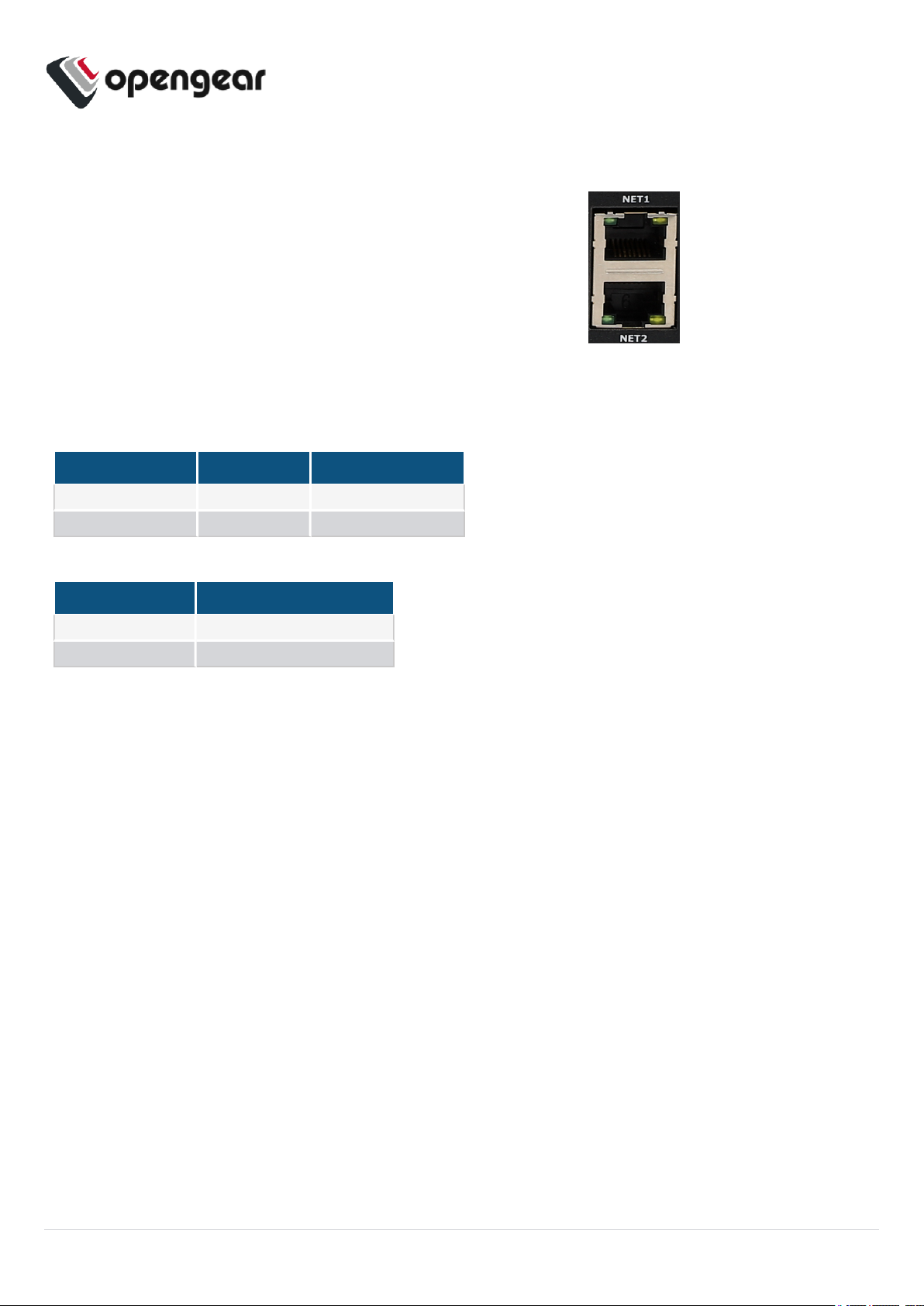
Using a computer on the same subnet as the static network interface shown in "Hardware Installation" on
page1, access the web UI with your web browser at https://192.168.0.1/ .
Note: The device has a self-signed SSLcertificate. Your browser will display an "Untrusted
connection"warning. Click through the warning to access the login page.
To log in for the first time, enter the username root and password default and click Submit.
Step 2. Change Root Password
When logging in to the device for the first time you will be prompted to change the root password
immediately.
Enter the current password followed by the new password and click Log in.
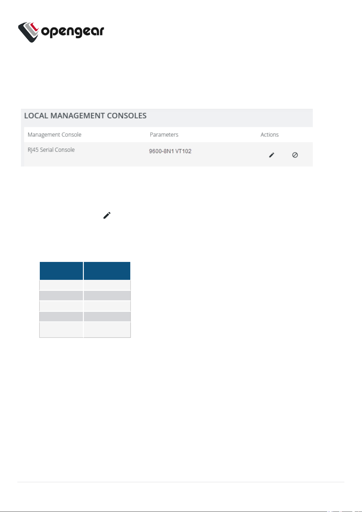
The ACCESS > Serial Ports page appears displaying a list of connected serial devices and links to a
Web Terminal or SSH connection for each.
CONFIGURE SNMPPOWER ALERTS
Configure > SNMP Alerts > Power > Voltage
Configure the System Voltage Range alert to send an SNMPTRAPwhenever the system reboots or the
voltage on either power supply leaves or enters the user-configured voltage range.
For more details, consult the Console Manager User Guide:
https://opengear.com/support/documentation/.
8

CONFIGURE SERIAL PORTS
To change settings for individual serial ports:
1. Navigate to CONFIGURE >Serial Ports.
2. Click the Edit button next to the port you wish to modify.
3. Change port settings, logging settings or configure IP aliases.
4. Click Apply to save changes.
Field Value
Mode ConsoleServer
Pinout X2
Baud Rate 9600
Data Bits 8
Parity None
Stop Bits 1
Table: Default configuration for serial ports
9

CONFIGURE LOCAL CONSOLE
CONFIGURE>Local Management Consoles
Console Manager CM8100 units contain one RJ45 serial console.
To configure local console ports:
1. Navigate to CONFIGURE > Local Management Consoles.
2. Click the Edit button next to the local console you wish to modify.
3. Change port settings.
4. Click Apply to save changes.
Field Value
Baud Rate 9600
Data Bits 8
Parity None
Stop Bits 1
Emulation VT102
Table: Default serial port configuration for local console access
10

CONFIGURE NETWORK
CONFIGURE >Network Connections >Network Interfaces
Click to expand any row to display status information about the interface and its connections.
Configure Physical Interfaces
Click the Edit button to configure media and MTU for the any of the physical interfaces.
Modify Default IPv4 Static Interface
1. Click the "IPv4 Static" label under NET1 to open the edit connection page.
2. Enter the IPv4 address.
3. Enter the network mask.
4. Click Apply to save changes.
11

CREATE NEW ADMINISTRATIVE USER
Note: You should create a new administrative user rather than continuing as the root user.
1. Navigate to CONFIGURE>User Management >Local Users.
2. Click the Add User button at the top-right of the page.
3. Click the User Enabled checkbox.
4. Enter Username and Password.
5. Assign the admin group to the user to provide full access privileges.
6. Click Save User to create the new user account.
7. Log out and log back in as this user for all administrative functions.
For more details about Users and Groups configuration, consult the Console Manager User Guide:
https://opengear.com/support/documentation/.
12

ACCESS DEVICE CONSOLES
After you have attached managed devices and configured serial ports by following "Configure Serial
Ports" on page9, you can now access the console of your managed devices on your network.
Web UI
1. Navigate to ACCESS >Serial Ports to view the list of serial ports on the device.
2. Click the Web Terminal button to the right of any serial port in Console Server mode to access it
via the web terminal.
Console
For administrator users logged in to the device via console or SSH:
1. Type pmshell to view the list of available managed devices.
2. Enter the port number to access the desired device and press Enter.
SSH
The managed devices connected to the Console Manager can be accessed directly with an SSH
command to connect to the device.
lTo view the list of managed devices: ssh <username>+serial@<device address>
lTo connect to a specific device by port:ssh <username>+port<number>@<device address>
lTo connect to a specific device by name:ssh <username>+<port label>@<device address>
Note: The SSHdelimiter can be modified via the Web UIat CONFIGURE>Services >SSH.
Telnet
Telnet access to managed devices is not supported at this time.
13

LIGHTHOUSE CENTRALIZED MANAGEMENT
Note: Lighthouse is a powerful tool that simplifies the way you manage your out-of-band network
through a single pane of glass. Better control and visibility provides 24/7 resilient access to your
connected ITinfrastructure. For more information, visit https://opengear.com/products/lighthouse/.
To enroll your device:
1. Navigate to CONFIGURE >Lighthouse Enrollment.
2. Click the Add Lighthouse Enrollment button at the top-right of the page.
3. Enter the Lighthouse Address, Enrollment Token, optional port and optional Enrollment Bundle.
4. Click Apply to begin the enrollment process.
Note: Enrollment of an Opengear device can also be performed from Lighthouse using AddNode
functionality.
14
This manual suits for next models
5
Table of contents