1. PACKAGING
Following list of parts is included inside CS-503
package:
1. CS-503 cascade controller
2. 4 pcs of RS connection cable (5m)
3. 230V power supply cord
4. User manual
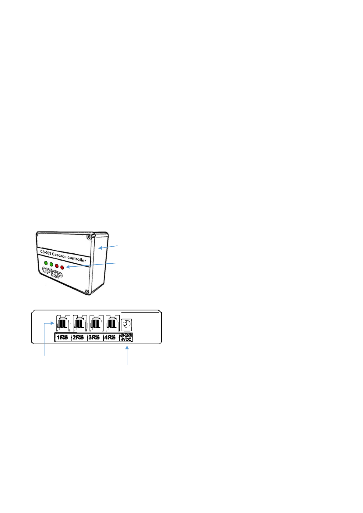
2. BASIC DESCRIPTION
1. CS-503 controller
2. 4pcs of RS connectors,
for connection of each boiler enabling multi-
structural communication provided by cascade
controller.
3. Indication diodes,
which indicates real time boiler operation.
Light indicates that boiler is in operation, no
light indicates that boiler is turned off by
cascade controller.
4. Power supply cord,
to connect controller to the electricity.
Main box
Indication diodes
No light –boiler off
Light –boiler on
RS outputs for boiler connection
Power supply cable
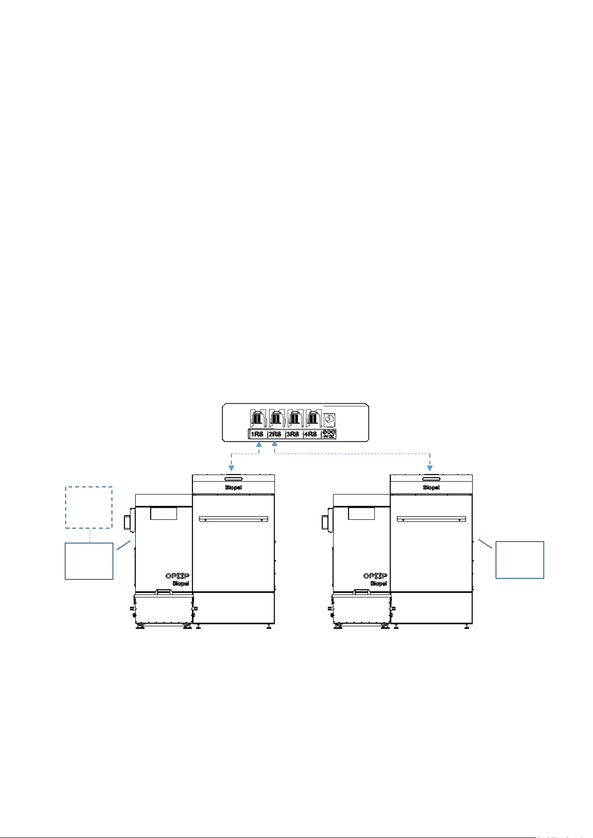
CS-503 cascade controller should be connected close
to the boilers to connect each of them with 5m RS cable
supplied in standard delivery.
Position all cables in a way to protect them against
physical and heat damage.
Device should not be installed close to other
electromagnetic devices such as motors, fans of the
boiler. Safe distance is at least 50cm.
3. TECHNICAL SPECIFICATION
Following list is specification of basic electrical and
other technical values.
Power supply 230V
Power consumption 1W
Maximal current 250mA
CS-503 diameters:
oHeight 20mm
oLength 100mm
oDepth 40mm
RS connection cable:
oLength 5m
oConnector RS
Max operational temp. -20 to 45°C
Package weight 35g
4. SAFETY REQUAREMENTS
Read these instructions carefully to make sure CS-503
will work without any problem in all conditions.
Do not install any kind of cascade controller
equipment directly on boiler or boiler
equipment surface to protect device and
cables against high temperatures.
Cables connecting each boiler should be
covered and positioned in a safe way, so no
heat ash or dust will damage them in long term
use.
Prevent installation of electronical
components in boiler rooms with high
humidity.
CS-503 cascade controller shouldn’t be
installed close to any kind of wireless or
electromagnetically operated device. Safe
distance is 50cm or more.
Update boiler control unit to the latest
firmware version to make sure cascade
operation is included in controller’s submenu.
Communicate the exact way of operation with
your installer to be sure cascade controller
operates all boilers in a way you need.
Consider both possible operations with CH
boiler temperature sensor and outside
Weather sensor.
Weather sensor is included in 431N module
packaging which is part of each burner box. To
make weather cascade operation work, also
431N module must be installed into the boiler
connected in 1st RS output of cascade
controller.