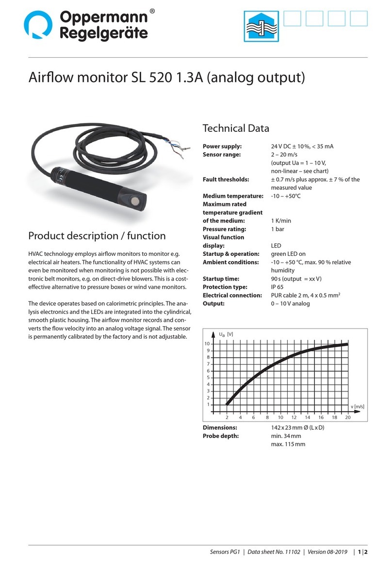
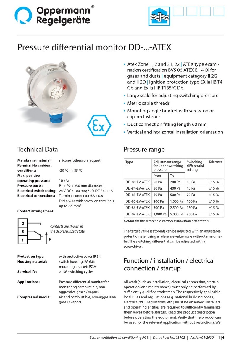
Oppermann Regelgeräte SENSO-X VPX User manual

Volume ow indicator / monitor / transmitter
SENSO-X® VPX
Sensors PG1 | Data sheet No. 13170 | Version 03-2020 | 1|6
• Large LCD display
• Volume ow up to 99,999 displayed in
numerals or as an indicator bar in any of the
following units: m³/h, l/s, ft³/min
• Limit displayed up to max. volume ow
• Working range displayed (Range max)
• Three-color LED: red for limit value undershoot,
yellow for fault and green for overshoot
• Temperature / Absolute pressure transducer
• NFC parametrisation of limit, range max,
signal range for analog output, K-factor and
air density ρ
• Optional Modbus output
• Power supply: 24 V AC at 50/ 60 Hz or 24 V DC
• Available in two built-in and one surface-
mounted versions
Technical data
Housing: high impact ABS
Front panel color: antique white
Lower housing color: anthracite
Protection class: surface-mounted type (AP) IP 65
built-in type IP 54 /
built-in type with additional sealing
(accessory) IP64
Operating temperature: -20 °C to 65 °C
Storage temperature: -20 °C to 70 °C
Relative humidity: max. 95 % non-condensing
Front cover dimensions
- square: 182 x 140 x 21 mm [L x W x H]
- round: 143 mm Ø
Dimensions of
surface-mounted type: 165 x 71 mm [Ø x T]
Hose connection: 2x 6 mm Ø
Working and
measuring ranges: see table
Working range: adjustable via keys and NFC tool
Burst pressure: 20 kPa (VPX1000)
40 kPa (VPX4000)
Protection class: II (IEC 60536)
Error margin: +/- 1 % of measuring range
(@ -5 to 65 °C)
Power consumption: 24 V DC 41 mA
24 V AC 81 mA
Long-term stability: ≤ ± 0.5 % FS/a
Supply voltage: 13.5 – 36 V DC or
13.5 – 30 V AC at 50/60 Hz
Output analog: linear 0 – 10 V (max. 0.1 mA) or
4 – 20 mA (max. load 600 Ω).
Output digital: relay (250 V AC 6 A, 30 V DC 5 A),
changeover switch, closed-circuit
principle, freely selectable limit value.
Modbus optional.
Cable gland: M16
Cable connection: Spring terminals 0.2 – 1.5 mm²
Installation
All work (such as installation, electrical connection, startup, ope-
ration, and maintenance) must only be performed by suciently
qualied tradesmen. The respectively applicable local rules and
regulations (e.g. national building codes, electrical/VDE regula-
tions, etc.) must be observed. Installers and operating entities
are required to suciently familiarize themselves before startup.
Read the product description before operating the equipment.
Verify that the product can be used for the relevant application
without restrictions. We are not liable for printing errors and
changes after printing. Appropriate use implies compliance with
operating and installation instructions. We are not liable for losses
due to inappropriate use. Unauthorized or inappropriate mani-
pulations or modications of the device render the operating
permit, the product warranty and warranty claims null and void.
Types
TypeType MeasuringMeasuring
rangerange
Working rangeWorking range
(output signal)(output signal)
Units ofUnits of
measure /measure /
output*output*
Limit valueLimit value
monitoringmonitoring
VPX1000 0 – 1,000 Pa 0 – 99,999 m³/h
freely adjustable in
1 m³/h-increments
m³/h, l/s,
ft³/min
Freely selectable.
LED/bar -indicator +
switching output for
undershoot
VPX4000 0 – 4,000 Pa 0 – 99,999 m³/h
freely adjustable in
1 m³/h-increments
m³/h, l/s,
ft³/min
Freely selectable.
LED/bar -indicator +
switching output for
undershoot
* analog output 0 – 10 V or 4 – 20 mA linear depending on selected working range and unit of
measure.

Volume ow indicator / monitor / transmitter SENSO-X® VPX
2|6| Sensors PG1 | Data sheet No. 13170 | Version 03-2020
Built-in version
Mill a 115 mm Ø hole in the sandwich plate or cabinet door
and push the functional part through the opening from the
front. The mounting direction is indicated by an arrow pointing
upward on the back of the device. Screw the threaded rod
into the threaded sleeve with a screwdriver; slip the mounting
bracket over it and secure with a wing nut. When connecting
the pressure transfer hoses, care must be taken to comply with
the direction of the pressure (+/-). Finally, the front panel can be
snapped into place.
Surface-mounted housing
Screw the functional part onto a wall, duct or similar and then
connect it to the power and pneumatic lines. Then slip the ring
cover over the functional part and snap on the front cover.
Design
The built-in version of the SENSO-X®VPX consists of a round
section and a square or round front cover. The instrument is
optimized for installation in ventilation devices and control
cabinets. The two pressure test points, marked + (positive
pressure side) and - (negative pressure side), are sunk into the
housing on the back. In the middle is a threaded sleeve. Attach
the retaining bracket using the supplied threaded rod and wing
nut. The wing nut is secured against loosening. Two cable
breakthroughs are provided on the back of the housing. Two
M16 x 1.5 screw joints are included in the assembly kit. An
integrated O-ring serves to seal the functional part against the
mounting surface. The arrow on the back of the device points
upward in the correct mounting position.
The surface-mounted version of the SENSO-X® VPX consists of
a round functional part with three screw-on mounting brackets,
a ring cover and a snap-on front cover. The two measurement
connections, marked + (positive-pressure side) and – (negative-
pressure side), exit at the bottom. Exiting at the bottom are also
two strain relief elements.
Built into the functional part in all versions, and visible from the
front, are an LCD display, an LED to indicate when limit values
are exceeded and 4 function keys.
After installation and conguration of the device, the front
cover is snapped onto the functional part. Due to 3 guided
notches this is only possible in the correct position. Removing
the front cover is done by pulling with both hands or by using
a screwdriver.
Operating principle
The measured dierential pressure is transmitted via exible
hoses and connecting nipples onto the piezoelectric dierential
pressure sensor, electronically evaluated, converted into units of
volume ow taking into account the programmed k-factor and
density ρ and displayed on the LCD indicator.
This calculation is based on the following formula
Vh = volume flow [m³/h]
K = K-factor [m²s/h]
∆p = differential pressure [Pa]
ρ = air density [kg/m³]
Vh= K x √2 x ∆p
ρ
Note: Many fan manufacturers use simplied basic formulas
and accordingly modied K-values. State the manufacturer
when entering the K-factor, and the transmitter will take
this into account. Please refer to the table below for identi-
ers of the most common manufacturers:
Non-binding information. Please note the current
data sheets of the manufacturers. Subject to change. If the
manufacturer of your choice is not listed, enter the K-factor
manually. Use the setting D =“Uni” for this purpose. This is also
the default setting.
The additional parameter“No. of fans”allows for fan walls/fan
grids. Enter the number of fans. The default setting is 1.
Activation and operation
Make all electrical connections before connecting the supply
voltage. Connect the 24 V supply voltage with the correct polarity
to start up the SENSO-X® VPX.
The device is ready for use immediately.
To set the parameters either take o the front panel and enter
the desired settings via the 3 keys or use the NFC tool (Windows
program for PCs: see Specication Sheet 13180; or Android App
for smartphones / tablets in the Google Play Store).
Setting display unit (dimension)
A brief push of the lower key (S1) in normal operation mode swit-
Manufacturer
Manufacturer
identier
„Manufactor“
Example
types
Calculated
K-factor K1
transmitter
ebm-pabst A
R3G, K3K, …
K = 0,7746 * Kebm
Fläkt B
CXLF, GXLB,
GPEB, …
K = 2788,5 / KFläkt
Nicotra
Gebhardt C
RZR, RZA, …
K = KGebhardt
Rosenberg C DKH, GKH, … K = KRosenberg
Ziehl-Abegg A ER…C,
GR…C, … K = 0,7746 * KZiehl
Comefri C - K = KComefri
Unassigned
value / uni-
versal D - K =
(enter value)

Sensors PG1 | Data sheet No. 13170 | Version 03-2020 | 3|6
Volume ow indicator / monitor / transmitter SENSO-X® VPX
J1
J2
J3
LED
S1
S2 S3
ZERO
S5
ON
CO
NC
NO
24V
0V
Out mA
Out V
ches the setting back and forth between m³/h, l/s and ft³/min.
The volume ow is displayed in numerals and as an indicator
bar. The indicator bar serves to visualize the measured volume
ow in % in relation to the set working range (Range max).
Programming the SENSO-X® VPX
(valid from rmware 1.0.2.8)
While programming, the current values on the display and the
analog output are frozen. Hold down the lower key (S1) to enter
the programming mode. The adjustable parameter is displayed
in ashing mode. Press S1 repeatedly to move through the
menu in the following sequence:
• Limit (value) innitely adjustable between 0 and the upper
end of the working range
• Range max. (working range) innitely adjustable between 0
and 99,999m³/h, 27,777 l/s or 58,857 ft³/min.
• Out (analog output setting): 4 – 20 mA or 0 – 10 V
• MANUFACTOR (fan manufacturer identier): A to D
• K-factor, innitely adjustable between 0 and 6.553,5 (default 500)
• NO OF VENT (number of fans/ventilator in the fan grid):
1 (default) – 20
• Air density ρ, innitely adjustable between 0 and 2.0
(default 1.15 kg/m³)
• BUS ADDR* (Bus Address): 1 – 127
• BAUD* (Baud rate): 9.6k (default), 14.4k, 19.2k, 38.4k or
56k baud)
• PAR* (Paritätseinstellung Modbus): Even, Odd or None
• TEMP GRAD CEL (temperature on the circuit board in °C)
• PRESS AMBI hPA (absolute atmospheric pressure inside the
device housing, shown in hPa)
• SW VERS (Software version)
• FACTORY RESET (resets the device to factory settings)
* for Modbus versions only
Use the keys at the top left (S2) and top right (S3) to change the
parameter value shown in the ashing display area:
Short keystroke →single steps,
Long keystroke →increases rate of change
The LED changes color when the set limit value is reached: LED
red on limit value undershoot and green on overshoot.
The working range extends to the value in m³/h, l/s or ft³/min.
that corresponds to an analog output of 20 mA or 10 V. This
value can be set under the menu item Range max.
For example: set working range 20,000 m³/h
at 0 m³/h , the AO is 4 mA or 0 V
at 20,000 m³/h , the AO is 20 mA or 10 V
Save (OK)
After 10 s without a keystroke the set values are saved
automatically and the display and the analog output return to
operating mode.
Factory settings
To reset the device to its factory settings, select the menu item
Factory Reset. The display ashes“ZERO”. Hold down the“ZERO”
key for 3 s. Then the display ashes“DONE”. All previous settings
of the limit value and working range as well as any bus settings
return to their default values.
0-point adjustment
It is possible for volume ow readings to drift upwards or down-
wards by up to a few m3/h for a period of up to four weeks after
initial start-up. This is no defect. To compensate for this drift
you can perform a manual zero-point adjustment. Depressurize
the measurement inputs (draw o both hoses). Hold down the
ZERO key for ca. 3 s. The display ashes„ZERO“. Briey press the
S1 key. The device recalibrates and the display ashes “DONE”
for ca. 10 s.
Display of dierential pressure for verication purposes
On pressing keys S2 and S3 the measured dierential pressure is
displayed for as long as they are held down.
Electrical connection
If the relay is de-energized (falling below the limit or voltage
drop), COM and NC are connected.
For Modbus connection to terminal J1 see next page.
Caution:
Disconnect all power supplies before opening the housing.
The housing may only be opened by a trained electrician.
Observe supply and switching voltage ratings. Observe the
following symbols on the device:
Danger – High Voltage!
Disconnect power supply before working
on the device
Observe Instructions

Volume ow indicator / monitor / transmitter SENSO-X® VPX
4|6| Sensors PG1 | Data sheet No. 13170 | Version 03-2020
The sliding switch S5 is for inserting a 120 ohm terminal resistor.
Ex factory the switch is in o-position (OFF pos. = left).
Default (factory) Modbus settings
Baud rate: 9600
data bits: 8
start bits: 1
stop bits: 1
Modbus address: 1
parity: even
The following Modbus parameter options are available via the menu or the NFC tool conguration program:
bus adresse: 1-127
baud rate: 9.6k, 14.4k, 19.2k, 56k
parity: even (1 startbit, 8 datenbits, 1 stopbit),
odd (1 startbit, 8 datenbits, 1 stopbit),
none (1 startbit, 8 datenbits, 2 stopbits)
Implemented Modbus function: Read Holding Registers function 0x03
Register PWM
address Name File type Raw data Description
0 (0x00)
40001
pressure unsigned 16 0 to 1,000 or 4,000 measured dierential pressure in Pa
1 (0x01)
40002
limit (low word) unsigned 32 0 to 65,535 Set limit value in selected unit
of measure, see register 7, e.g.
0 to 99,999 m³/h
2 (0x02)
40002
limit (high word) 0 or 1
3 (0x03) 40004 output analog unsigned 16 0 or 1 0 = 0 – 20 mA or 0 – 10 V
1 = 4 – 20 mA or 2 – 10 V
4 (0x04) 40005 unassigned
5 (0x05) 40006 ow (low word) unsigned 32 0 to 65,535 calculated volume ow in m³/h
0 to 99,999
6 (0x06) 40007 ow (high Word) 0 or 1
Modbus connection diagram:
Note:
Floating switch contacts “CO,“NC”and “NO”may only be used for 230 V AC or
24 C AC/DC .
Disconnection or electrical protection equipment must be provided by the
customer. The 24V AC/DC supply voltage requires a local fuse for max. 6 A or
a supply unit with a power output limit of 6 A.
Caution:
All cable installation and connection work must be left to a duly qualied elec-
trician. Make sure that all cables are connected in accordance with the relevant
electrical regulations. The cable sheath must reach as close as possible to the
terminals. Braided wires longer than 10 mm must be secured near the terminal
with a cable clip or similar or must be insulated in pairs using, e.g., suitable shrink
tubing (see installation example).
Installation example:
Terminal J1 only present in bus version.
For electrical connections see previous page.
Modbus RTU
Overview of registers

Sensors PG1 | Data sheet No. 13170 | Version 03-2020 | 5|6
Volume ow indicator / monitor / transmitter SENSO-X® VPX
Example of Modbus telegram (hexadecimal notation)
Request:
Tx:[time stamp]- 01 03 00 05 00 02 D4 0A
from left to right:
“01”= Modbus address of SENSO-X, here = 1
“03”= function code “Read holding register”
“00”= high byte of start register (1st register to be read out), here = 0
“05”= low byte of start register, here register no. 5 = ow / volume ow, low word
“00 02”= number of registers read, here = 2
“D4 0A”= CRC
Response – ow / volume ow
Rx:[time stamp]- 01 03 04 0C B6 00 01 D9 45
from left to right:
“01”= responding Modbus address, here = 1
“03”= function code
“04”= number of response data bytes, here = 4
“0C” = high byte of 5th register, here = 0x0C00h = 3,072d
“B6”= low byte of 5th register, here = 0xB6h = 182d -> 182 + 3,072 = 3,254 m³/h
„00“ = high byte of 6th register, here = 0x000000h = 0d
„01“ = low byte of 6th register, here = 0x010000h = 65,536d -> 65,536 + 3,254 = 68,790 m³/h
“D9 45”= CRC
7 (0x07) 40008 unit of measure unsigned 16 4, 5 or 6 4: ft³/min
5: l/s
6: m³/h
8 (0x08) 40009 range max
(low word) unsigned 32
0 to 65,535 Set limit value in selected unit
of measure, see register 7, e.g.
0 to 99,999 m³/h
9(0x09) 40010 range max
(high word) 0 or 1
10 (0x0A) 40011 ρ (Rho) unsigned 16 0 to 200 air density in kg/m³ (default 1.15)
0 to 2.00
11 (0x0B) 40012 K-factor unsigned 16 0 to 65.535 correction factor (default 500,0)
0 to 6.553,5
12 (0x0C) 40013 temperature signed 16 -300 to 1,050 temperature on circuit board in
1/10°C from -30 to 105 °C
13 (0x0D) 40014 atmospheric
pressure unsigned 16 2,600 to 12,600 absolute atmospheric pressure
in housing in 1/10 hPa from
260 hPa to 1,260 hPa
14 (0x0E) 40015 sensor error unsigned 16 0 or 1 0 = no sensor error
1 = sensor error
15 (0x0F) 40016 measured limit unsigned 16 0 to 100 0 to 100 %
16 (0x10) 40017 state of
switching output unsigned 16 0 or 1 0 = inactive
1 = active
17 (0x11) 40018 LED status unsigned 16 0 to 3 0 = LED o
1 = green
2 = yellow
3 = red
18 (0x12) 40019 rmware version unsigned 16 1.0.1.1 and higher “1018”means FW version 1.0.1.8
19 (0x13) 40020 type unsigned 16 0 bis 4 0 = PPX1000
1 = PPX4000
2 = VPX1000
3 = VPX4000
20 (0x14) 40021 Modbus Address unsigned 16 1 to 127 1 to 127
21 (0x15) 40022 Fan manufacturer Unsigned 16 0 to 3 0 = A (ebm-pabst, Ziehl-Abegg)
1 = B (Fläkt)
2 = C (Nicotra Gebhardt, Rosenberg)
3 = D (unassigned/universal)
22 (0x16) 40023 Number of fans Unsigned 16 1 to 20 Number of fans in the fan grid

6|6| Sensors PG1 | Data sheet No. 13170 | Version 03-2020 Specications subject to change.
Oppermann Regelgeräte GmbH | Im Spitzhau 1 | 70771 Leinfelden-Echterdingen, Germany
Volume ow indicator / monitor / transmitter SENSO-X® VPX
Overview of the SENSO-X® PPX in its built-in version
3 keys
Wing nut
Square front type ... 00 Round front type ... 01
[
[0
[0
[
Housing base (Functional part in the built-in version)
Built-in versions
Surface mounted housing
[
[0
[0
[
[
[0
[0
[
[
[0
[0
[
This manual suits for next models
2
Table of contents
Other Oppermann Regelgeräte Measuring Instrument manuals