2| 2| Sensors PG1 | Data sheet No. 11102 | Version 08-2019 Specications subject to change.
Airow monitor SL 520 1.3A
Oppermann Regelgeräte GmbH | Im Spitzhau 1 | 70771 Leinfelden-Echterdingen, Germany
Phone +49 711 72723560 | Fax +49 711 7280527 | info@oprg.de | www.oprg.de
Arrow parallel to airow.
LED
Installation
Please observe these instructions. All work (such as installation,
electrical connection, startup, operation, and maintenance)
must only be performed by suciently qualied tradesmen. The
respectively applicable local rules and regulations (e.g. national
building codes, electrical/VDE regulations, etc.) must be observed.
Installers and operators are required to suciently familiarize
themselves before startup. Read the product description before
operating the equipment. Verify that the product can be used for
the relevant application without restrictions. We are not liable for
printing errors and changes after printing. Appropriate use implies
compliance with operating and installation instructions. We are
not liable for losses due to inappropriate use. Unauthorized or
inappropriate manipulations or modications of the device render
the operating permit, the product warranty and warranty claims
null and void.
The installation length of the sensor supports a maximum
probe depth of 115 mm into the air duct. The unit is installed
with the included installation clamp, which is attached to the air
duct with two sheetmetal screws. A mark on the sensor housing
ensures proper alignment with the ow.
min. 34 mm max. 115 mm
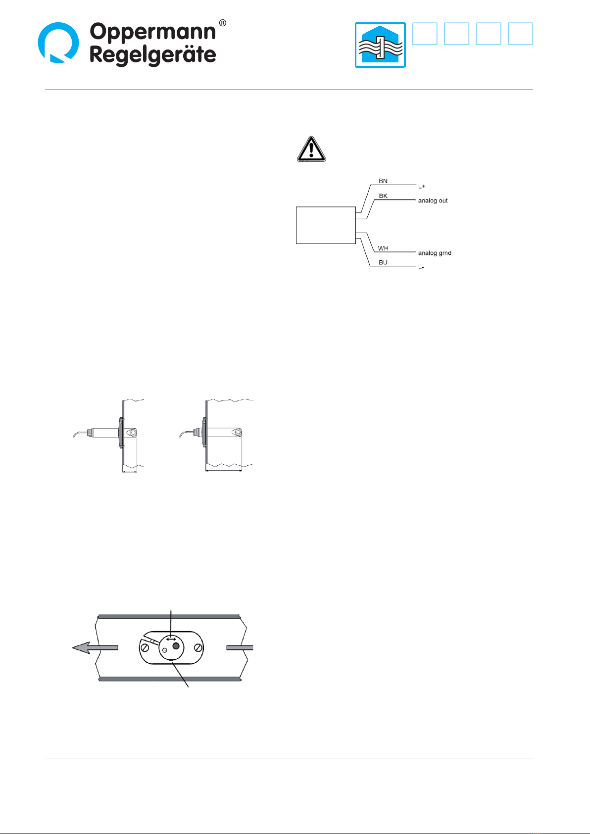
Electrical connection
Disconnect the system from power. Connect the sensor
as indicated on the type tag.
Operation
Verify reliable operation of the device. The green LED is on
when the power supply is on. The unit is operational approx. 90
s after the power supply is switched on. The output is tuned for
the measured value during the startup time of 90 s, after which
a stable sensor signal is available.
Core colors:
BN brown
BU blue
BK black
WH white
The airow monitor is clamped with the installation clamp. The
diameter of the bore in the air duct is 23 mm. The included foam
rubber gasket is placed between the duct and the installation
clamp as an air-tight seal. The sensor head must reach at least 34
mm (max. 115 mm) into the duct and be located within the zone
of maximum ow velocity. Avoid turbulence zones (clearance to
interfering elements 5xD upstream of sensor, 3xD downstream of
sensor).
Align the device with the airow. The arrow marked on the plug
must point in the direction of airow.


