Oppermann Regelgeräte OPP-SENS M Series User manual

Sensors PG2 | Data sheet No. 20910 | Version 02-2019 | 1| 9
OPP-SENS® Transducer (for PT1000) M-...
• 8-position captive lid
• IP 65 housing, including seal ring
• Fast wiring with screw-on cover and
spring terminals – no tools required
• 10-position oset: linear characteristic
line oset with rotating switch
• 10 sensor ranges selectable with
rotating switch
Optional:
• Illuminated display & operator
keyboard with capacitive buttons
• 5P calibration: Interpolation of the output cha-
racteristic line via 5 arbitrary reference points.
• BACnet / Modbus versions
with 3 cable threads
See specication sheet 20903 for suitable PT1000 cable sensors..
Technical data
Power supply:
2-wire 15 – 35 V DC
3-wire/MOD/BAC 15 – 35 V DC or 15 – 30 V AC
Current draw: See table on page 2
Outputs:
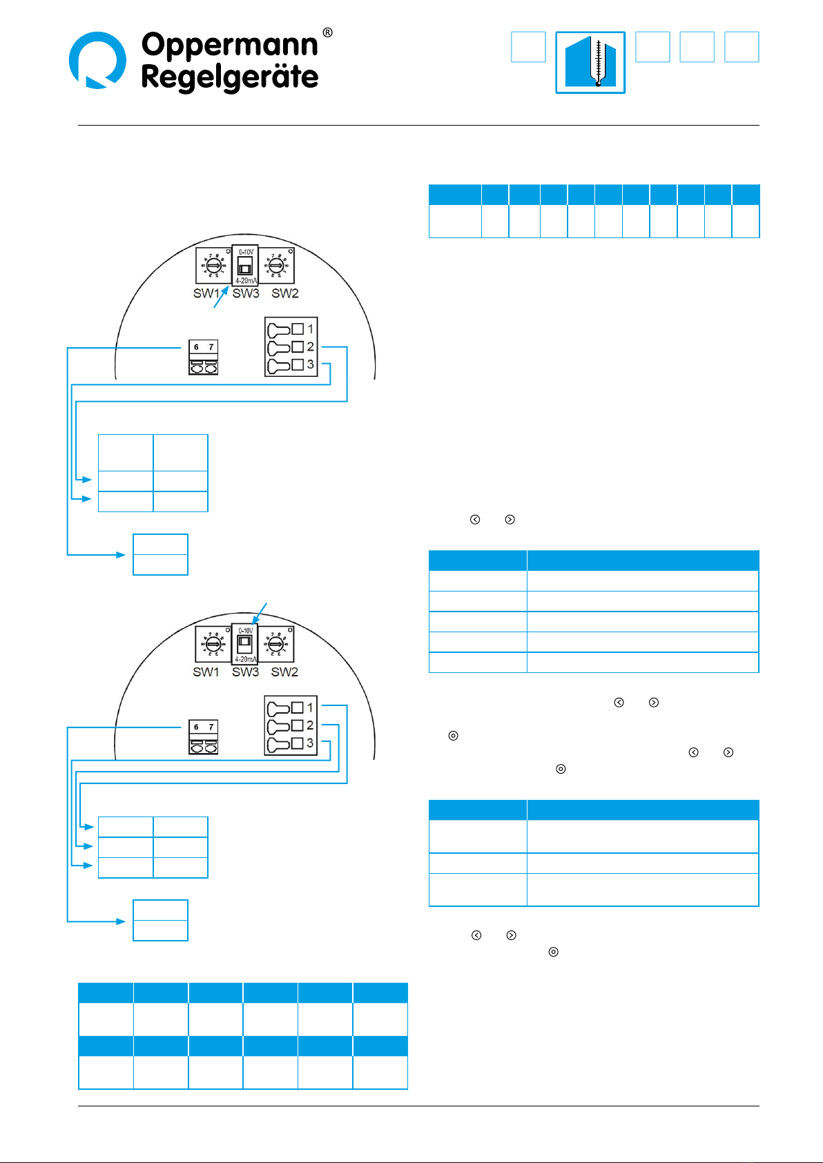
2-wire 4 – 20 mA, load < 500 Ω
(3.6 mA on fault)
3-wire 0 – 10 V, load > 10 kΩ or
4 – 20 mA, load < 500 Ω
(-0.3 V or 3.6 mA on fault)
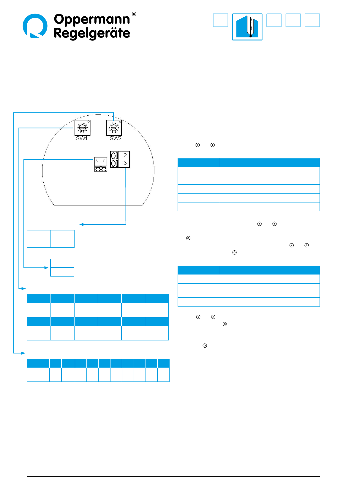
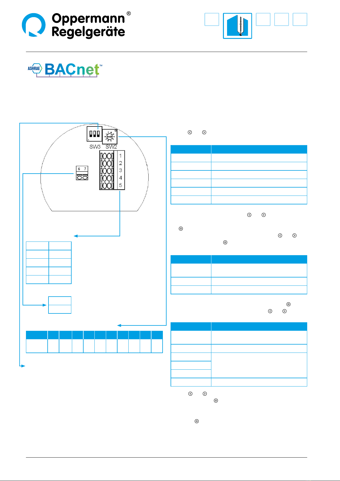
MOD/BAC digital
Adjustable sensor range:
-50...200/-20...150/-50...50 /
-20...80/-30...60/0...40/0...50 /
0...100* /0...150/0...200 °C
*default setting
Tolerance: ± 0.5 K at 25 °C, suitable
PT1000 sensor element required
Perm.
ambient conditions: -20 – 70 °C, 0 – 95 % RH
(non-condensing)
Sensor element: PT1000 cable sensor
(not included in the delivered scope)
Insulation resistance: ≥ 100 MΩ, 20 °C, 500 V DC
Housing: base: PBT, color similar to RAL 7016
display: PC, transparent
front panel
: PC, color similar to
RAL 7016
ring: PBT, color similar to RAL 1003
Strain relief: M16, PA, color similar to RAL 7001
Cable connection: spring terminals 0.2 – 1.5 mm²
Function
The transducer converts the passive PT1000 sensor signal into
0 – 10 V or 4 – 20 mA analog signals, or communicates the
temperature reading via Modbus or BACnet.
Installation
All work (such as installation, electrical connection, startup,
operation, and maintenance) must only be performed by suf-
ciently qualied tradesmen. The respectively applicable local
rules and regulations (e.g. national building codes, electrical/
VDE regulations, etc.) must be observed. Installers and opera-
ting entities are required to suciently familiarize themselves
before startup. Read the product description before operating
the equipment. Verify that the product can be used for the
relevant application without restrictions. We are not liable for
printing errors and changes after printing. Appropriate use
implies compliance with operating and installation instruc-
tions. We are not liable for losses due to inappropriate use.
Unauthorized or inappropriate manipulations or modications
of the device render the operating permit, the product warranty
and warranty claims null and void.
Transducer is fastened with 2 screws (max. ø 4 mm) on the two
mounting eyelets.

M-...
2| 9| Sensors PG2 | Data sheet No. 20910 | Version 02-2019
Drawing
Active transmitter
Description Technical data Type
Analog base transmitter
2-Wire / 3-Wire switchable
without Display*
Power supply 15 – 30 V AC/DC
Current draw 25 mA (24VAC) / 10 mA (24VDC)
Output 4 – 20 mA bzw. 0 – 10 V
M-T
2-Wire / 3-Wire switchable
with Display**
Power supply 15 – 30 V AC/DC
Current draw 90 mA (24VAC) / 30 mA (24VDC)
Output 4 – 20 mA bzw. 0 – 10 V
M-T-D
5P transmitter with 5-point calibration
Current transmitter (2-Wire/4 – 20 mA)
without Display*
Power supply 15 – 35 V DC
Output 4 – 20 mA
M-TC5P
Current transmitter (2-Wire/4 – 20 mA)
with Display**
Power supply 15 – 35 V DC
Output 4 – 20 mA
M-TC5P-D
Current/voltage transmitter
(3-Wire, 0 – 10 V/ 4 – 20 mA) switchable
without Display*
Power supply 15 – 30 V AC/DC
Current draw 25 mA (24VAC) / 10 mA (24VDC)
Output 4 – 20 mA bzw. 0 – 10 V
M-T5P
Current/voltage transmitter
(3-Wire, 0 – 10 V/ 4 – 20 mA) switchable
with Display
Power supply 15 – 30 V AC/DC
Current draw 90 mA (24VAC) / 30 mA (24VDC)
Output 4 – 20 mA bzw. 0 – 10 V
M-T5P-D
Modbus transmitter (Modbus RTU)
without Display*
Power supply 15 – 30 V AC/DC
Current draw 75 mA (24VAC) / 25 mA (24VDC)
M-MOD
Modbus transmitter (Modbus RTU)
with Display
Power supply 15 – 30 V AC/DC
Current draw 140 mA (24VAC) / 45 mA (24VDC)
M-MOD-D
BACnet transmitter (MS/TP)
without Display*
Power supply 15 – 30 V AC/DC
Current draw 75 mA (24VAC) / 25 mA (24VDC)
M-BAC
BACnet transmitter (MS/TP)
with Display
Power supply 15 – 30 V AC/DC
Current draw 140 mA (24VAC) / 45 mA (24VDC)
M-BAC-D
* A display is used once for programming / address assignment and 5P calibration.
** 2-wire display not illuminated.
ø 89
110
113
2x M16
2x M16
M12
43
13
Dimensions in mm
Analog versions Bus versions

Sensors PG2 | Data sheet No. 20910 | Version 02-2019 | 3| 9
M-...
Electrical connections/settings
Base temperature transmitter (2/3-wire)
M-T as 2-Wire:
Connection terminal
n.c. 1 Not connected (optional GND
only for display illumination)
24 V 2 Power supply (+) 24 V DC
out 3 Temperature output (4 – 20 mA)
6PT1000 cable sensor interface
7
M-T as 3-Wire:
Connection terminal
0 V 1 Ground (-)
24 V 2 Power supply (+) 24 V AC/DC
out 3 Temperature output (0 – 10 V)
6PT1000 cable sensor interface
7
SW1: Sensor range
Position 0 1 2 3 4
Range
[°C] -50…200 -20…150 -50…50 -20…80 -30…60
Position 5 6 7 8 9
Range
[°C]
0…40 0…50 0…100 0…150 0…200
SW2: 10-position temperature oset
Position 0 1 2 3 4 5 6 7 8 9
Oset
[°C] 0 +0,5 +1 +1,5 +2 -2,5 -2 -1,5 -1 -0,5
SW3: Setting: 4 – 20 mA = 2-wire mode (4 – 20 mA)
Setting: 0 – 10 V = 3-wire mode (0 – 10 V)
Menu display
Valid from sensor rmware 0.34 and display rmware 0.56:
The device has got 2 hierarchical menu levels:
– main menu
– conguration menu (simple parameters)
Use the and buttons to move through the menu.
In the main menu the following information is displayed:
Display Description
Temp °C
Temperature
Unit
Temperature UoM °C or °F
Type
Hardware version/sensor
Ver Sen
rmware revision of the sensor
Ver Dis rmware revision of the display
By simultaneously pressing the two and buttons for about
4 seconds, the conguration menu is started. By pressing
the button the currently displayed value can be changed.
The variable value will ash, it is changed with the and
buttons. By pressing the button again, the entered value is
stored. The following data can be displayed or changed here:
Display Description
Time s
illumination time of the display in seconds
(not for 2-wire mode)
Contr. %
display contrast (default 50%)
Norm % simulation of the analog output
e.g. 50 % = 5 V or 12 mA
Buttons and are used to navigate the configuration menu.
By pressing the button for approx. 4 seconds (or if no button
is pressed for approx. 1 minute), the device leaves the configu-
ration menu and returns to the main menu.

M-...
4| 9| Sensors PG2 | Data sheet No. 20910 | Version 02-2019
Electrical connections/settings
5P transmitter with 5-point calibration
(2-Wire version, current transmitter only)
2-Wire-version (M-TC5P):
Connection terminal
24 V 2 Power supply (+) 24 V DC
out1 3 Temperature output (4 – 20 mA)
6PT1000 cable sensor interface
7
SW1: Sensor range
Position 0 1 2 3 4
Range
[°C] -50…200 -20…150 -50…50 -20…80 -30…60
Position 5 6 7 8 9
Range
[°C]
0…40 0…50 0…100 0…150 0…200
SW2: 10-position temperature oset
Position 0 1 2 3 4 5 6 7 8 9
Oset
[°C] 0 +0,5 +1 +1,5 +2 -2,5 -2 -1,5 -1 -0,5
Menu display
Valid from sensor rmware 0.27 and display rmware 0.56:
The device has got 3 hierarchical menu levels:
– main menu
– conguration menu (simple parameters)
– password level (complex parameters, 5P-calibration)
Use the and buttons to move through the menu.
In the main menu the following information is displayed:
Display Description
Temp °C
Temperature
Unit
Temperature UoM °C or °F
Type
Hardware version/sensor
Ver Sen rmware revision of the sensor
Ver Dis rmware revision of the display
By simultaneously pressing the two and buttons for about
4 seconds, the conguration menu is started. By pressing
the button the currently displayed value can be changed.
The variable value will ash, it is changed with the and
buttons. By pressing the button again, the entered value is
stored. The following data can be displayed or changed here:
Display Description
Contr. %
display contrast (default 50%)
Norm %
simulation of the analog output
e.g. 50 % = 12 mA
Passwd Password entry „0000“*
Buttons and are used to navigate the parameter menu. By
pressing the button for approx. 4 seconds (or if no button is
pressed for approx. 1 minute), the device leaves the parameter
menu and returns to the configuration menu. By pressing
the button again for 4 seconds (or if no button is pressed
for approx. 1 minute), the device returns to the main menu.
* In older rmware versions, only the password„0815“ is accepted.

Sensors PG2 | Data sheet No. 20910 | Version 02-2019 | 5| 9
M-...
Electrical connections/settings
5P transmitter with 5-point calibration
(3-Wire version current/voltage)
3-Wire-version (M-T5P):
Connection terminal
0 V 1 Ground (-)
24 V 2 Power supply (+) 24 V AC/DC
out1 3 Temperature output
6PT1000 cable sensor interface
7
SW1: Sensor range
Position 0 1 2 3 4
Range
[°C] -50…200 -20…150 -50…50 -20…80 -30…60
Position 5 6 7 8 9
Range
[°C]
0…40 0…50 0…100 0…150 0…200
SW2: 10-position temperature oset
Position 0 1 2 3 4 5 6 7 8 9
Oset
[°C] 0 +0,5 +1 +1,5 +2 -2,5 -2 -1,5 -1 -0,5
SW3 Position 1: ON = Analog output 0 – 10 V
OFF = Analog output 4 – 20 mA
Menu display
Valid from sensor rmware 0.27 and display rmware 0.56:
The device has got 3 hierarchical menu levels:
– main menu
– conguration menu (simple parameters)
– password level (complex parameters, 5P-calibration)
Use the and buttons to move through the menu.
In the main menu the following information is displayed:
Display Description
Temp °C
Temperature
Unit
Temperature UoM °C or °F
Type
Hardware version/sensor
Ver Sen rmware revision of the sensor
Ver Dis rmware revision of the display
By simultaneously pressing the two and buttons for about
4 seconds, the conguration menu is started. By pressing
the button the currently displayed value can be changed.
The variable value will ash, it is changed with the and
buttons. By pressing the button again, the entered value is
stored. The following data can be displayed or changed here:
Display Description
Time s
illumination time of the display in seconds
(0 = illumination always on)
Contr. %
display contrast (default 50%)
Norm % simulation of the analog output
e.g. 50 % = 5 V or 12 mA
Passwd Password entry „0000“*
Buttons and are used to navigate the parameter menu. By
pressing the button for approx. 4 seconds (or if no button is
pressed for approx. 1 minute), the device leaves the parameter
menu and returns to the configuration menu. By pressing
the button again for 4 seconds (or if no button is pressed
for approx. 1 minute), the device returns to the main menu.
* In older rmware versions, only the password„0815“ is accepted.

M-...
6| 9| Sensors PG2 | Data sheet No. 20910 | Version 02-2019
Electrical connections/settings
Modbus transmitter with 5-point calibration
Modbus-version (M-MOD):
Connection terminal
0 V 1 Ground (-)
24 V 2 Power supply (+) 24 V AC/DC
A 3 Modbus RS485A (Data+)
B 4 Modbus RS485B (Data-)
S 5 Clamping support for shield
6PT1000 cable sensor interface
7
SW2: 10-position temperature oset
Position 0 1 2 3 4 5 6 7 8 9
Oset
[°C] 0 +0,5 +1 +1,5 +2 -2,5 -2 -1,5 -1 -0,5
SW3 Position 3: ON = 120 Ω termination active
Menu display
Valid from sensor rmware 0.28 and display rmware 0.56:
The device has got 3 hierarchical menu levels:
– main menu
– conguration menu (simple parameters)
– password level (complex parameters, 5P-calibration)
Use the and buttons to move through the menu.
In the main menu the following information is displayed:
Display Description
Temp °C
Temperature
Unit
Temperature UoM °C or °F
MB Addr
Modbus address
Type
Hardware version/sensor
Ver Sen rmware revision of the sensor
Ver Dis rmware revision of the display
By simultaneously pressing the two and buttons for about
4 seconds, the conguration menu is started. By pressing
the button the currently displayed value can be changed.
The variable value will ash, it is changed with the and
buttons. By pressing the button again, the entered value is
stored. The following data can be displayed or changed here:
Display Description
Time s
Illumination time of the display in seconds
(0 = illumination always on)
Contr.%
Display contrast (default 50 %)
Passwd Password entry „0000“*
After correctly entering the password (by pressing the button
jumps to the next position, using the buttons and changed
to the respective number) the following menu appears:
Display Description
MB Mode Modus (RTU or ASCII)
MB Baud baud rate (9.6, 19.2, 38.4 oder 56.0)
MB Pari Parity (Even, Odd or None)
MB Addr Modbus address
CTX1 °C
calibration -> see page 9...
CTY5 °C
Res. All Reset to default settings
Buttons and are used to navigate the parameter menu. By
pressing the button for approx. 4 seconds (or if no button is
pressed for approx. 1 minute), the device leaves the parameter
menu and returns to the configuration menu. By pressing
the button again for 4 seconds (or if no button is pressed
for approx. 1 minute), the device returns to the main menu.
* In older rmware versions, only the password„0815“ is accepted.
Note:
For quick programming of Modbus
parameters, we recommend our
Parameter programming tool
PROG-MOD-01.
See Data sheet No. 20914.

Sensors PG2 | Data sheet No. 20910 | Version 02-2019 | 7| 9
M-...
Bus settings
Modbus protocol
Mode: Sensor setting (default RTU) selectable RTU / ASCII
Baud rate: Sensor setting (default 9.6 (= 9600)) selectable 9.6 / 19.2 / 38.4 / 56.0
Parity: Sensor setting (default Even) selectable Even / Odd / None
Address: Sensor setting (default 1) selectable 1 to 127
ATTENTION: Changes take immediate eect without restarting the transmitter.
Data bits: 8 (in RTU mode); 7 (in ASCII mode)
Stop bits: 1 (for parity Even / Odd); 2 (for parity None)
Functionality: 04 Read Input Registers (3x)
Register overview
Register PWM address Data type Unit of Measure Description
10 (0x0A)
30011
Signed 16 1/10 °C Temperature °C
11 (0x0B)
30012
Signed 16 1/10 °F Temperature °F
16 (0x10) 30017 Signed 16 0 = no sensor fault
1 = sensor fault Fault status
Request to transmitter (RTU example)
Byte Byte 0 Byte 1 Byte 2 Byte 3 Byte 4 Byte 5 Byte 6 Byte 7
Description Address Function Start address Count Register CRC
Example 01 04 000A 0002 …
Meaning Transmitter 1 Read input
registers Register 10
(PWM 30011) 2 Register Checksum
Transmitter response (RTU example)
Byte 0 Byte 1 Byte 2 Byte 3 Byte 4 Byte 5 Byte 6 Byte 7 Byte 8
Description Address Function Number of
data bytes Temperature
in 1/10 °C Temperature
in 1/10 °F CRC
Example 01 04 04 00EC 02E9 …
Meaning Transmitter
1Read input
registers 4 Data bytes 236 (=23,6°C) 745 (=74,5°F) Checksum
Data type Signed 16 Signed 16

M-...
8| 9| Sensors PG2 | Data sheet No. 20910 | Version 02-2019
Electrical connections/settings
BACnet transmitter with 5-point calibration
BACnet-version (M-BAC):
Connection terminal
0 V 1 Ground (-)
24 V 2 Power supply (+) 24 V AC/DC
A 3 BACnet (MS/TP), RS485A (Data+)
B 4 BACnet (MS/TP), RS485B (Data-)
S 5 Clamping support for shield
6PT1000 cable sensor interface
7
SW2: 10-position temperature oset
Position 0 1 2 3 4 5 6 7 8 9
Oset
[°C] 0 +0,5 +1 +1,5 +2 -2,5 -2 -1,5 -1 -0,5
SW3 Position 3: ON = 120 Ω termination active
Menu display
Valid from sensor rmware 0.30 and display rmware 0.56:
The device has got 3 hierarchical menu levels:
– main menu
– conguration menu (simple parameters)
– password level (complex parameters, 5P-calibration)
Use the and buttons to move through the menu.
In the main menu the following information is displayed:
Display Description
Temp °C
Temperature
Unit
Temperature UoM °C or °F
Bac MAC BACnet MACaddress
Type
Hardware version/sensor
Ver Sen rmware revision of the sensor
Ver Dis rmware revision of the display
By simultaneously pressing the two and buttons for about
4 seconds, the conguration menu is started. By pressing
the button the currently displayed value can be changed.
The variable value will ash, it is changed with the and
buttons. By pressing the button again, the entered value is
stored. The following data can be displayed or changed here:
Display Description
Time s
Illumination time of the display in seconds
(0 = illumination always on)
Contr.%
Display contrast (default 50 %)
Passwd Password entry „0000“*
After correctly entering the password (by pressing the button
jumps to the next position, using the buttons and changed
to the respective number) the following menu appears:
Display Description
Bac Bd Baudrate (9.6 (Default),
19.2, 38.4, 57.6, 76.8, 115.2 or auto)
Bac MAC BACnet MAC addresse (1 – 127, Default 99)
CTX1 °C
calibration -> see page 10...
CTY5 °C
Res. All Reset to default settings
Buttons and are used to navigate the parameter menu. By
pressing the button for approx. 4 seconds (or if no button is
pressed for approx. 1 minute), the device leaves the parameter
menu and returns to the configuration menu. By pressing
the button again for 4 seconds (or if no button is pressed
for approx. 1 minute), the device returns to the main menu.
* In older rmware versions, only the password„0815“ is accepted.
The OPP-SENS_BACnet_Dokumentation (PICS, EPICS, EDE
and BTL certicate) can be found on our website
http://www.oprg.de/en/downloads/technical-information/
fully in one zip-le.

Specications subject to change. Sensors PG2 | Data sheet No. 20910 | Version 02-2019 | 9| 9
M-...
Oppermann Regelgeräte GmbH | Im Spitzhau 1 | 70771 Leinfelden-Echterdingen, Germany
Y (output value)
max
1
2
3
4
5
min
maxmin
x (sensor
measuring
value)
5P calibration
5-point calibration can be performed with all transmitters with
„5P“ in the article name and all Modbus and BACnet transmit-
ters. (optional display required)
5 reference locations can be arbitrarily positioned as X (sensor
reading) and Y (output value) between the two limit values. A
linear interpolation is performed between these reference locati-
ons (see gure).
A reference location in X and Y cannot be positioned beyond
the sensor limit values. The X values of the reference locations
must follow a monotone sequence of 1-2-3-4-5. Non-monotone
X values are ignored. The following gures illustrate this:
Reference location 4 is ignored because the function shown in
the lower left gure between reference locations 3 and 4 is not
denitive (dotted line).
If more than 5 calibration points are used, the X values of not
used reference locations must be set to the lower limit value
(minimum adjustment setting) or the upper limit value (maxi-
mum adjustment setting).
The associated Y value remains arbitrary
The calibration menu is opened by entering the character
sequence„0000“* in the„Passwd“ menu item of the congura-
tion menu (one advances to the next character by pressing the
keys; the relevant number is changed with the keys).
The following selections are then available:
Menu screen description Default
CTX1 °C
1. Screen Sensor reading
20.0
CTY1 °C
1. Screen Output value
20.0
CTX2 °C
2. Screen Sensor reading
65.0
CTY2 °C 2. Screen Output value 65.0
CTX3 °C 3. Screen Sensor reading 85.0
CTY3 °C 3. Screen Output value 85.0
CTX4 °C 4. Screen Sensor reading 100.0
CTY4 °C 4. Screen Output value 100.0
CTX5 °C 5. Screen Sensor reading 123.0
CTY5 °C 5. Screen Output value 123.0
Res. All Reset to default settings
The„Res. All“ button in the menu screen must be pressed for
approx. 4 seconds to reset all values to their default setting. The
display blinks during these 4 seconds.
The display reads„done“ when the reset is complete.
* In older rmware versions, only the password„0815“ is accepted.
Original characteristic curve
End-values range
5P calibration
Y (output value)
max
1
2
3
4
5
min
maxmin
x (sensor
measuring
value)
x
x
x
x
x
x
x
Table of contents
Other Oppermann Regelgeräte Transducer manuals
Popular Transducer manuals by other brands

NK TECHNOLOGIES
NK TECHNOLOGIES AT 2 Series instructions

Thyracont
Thyracont VSP63MA4 operating instructions

FSM
FSM DS01+ operating instructions

Siemens
Siemens SICAM T 7KG966 Product information

Simrad
Simrad SUPPORT BEAM MOUNTING - SCHEMA REV A manual

Camille Bauer
Camille Bauer 136590 operating instructions

Clark Synthesis
Clark Synthesis TST239 specification

gefran
gefran ONP1-A Series installation manual

Trimec
Trimec DUALPULSE 490 instruction manual

Thyracont
Thyracont VSH87E operating instructions

Lowrance
Lowrance Simrad LiveSight Ice installation guide

Airmar
Airmar DT800 Owner's guide & installation instructions