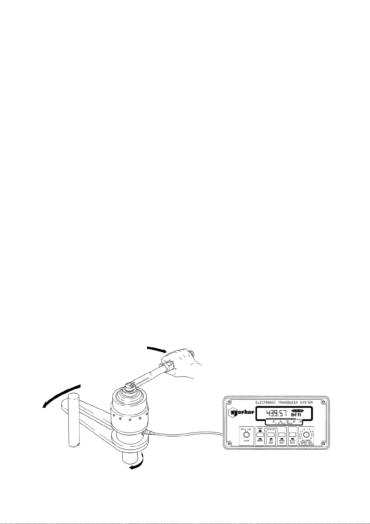
norbar PNEUTORQUE PT 1 User manual

OPERATOR’S MANUAL
ANNULAR TORQUE TRANSDUCER AND AMPLIFIER
FOR USE WITH ELECTRONIC TRANSDUCER SYSTEM (E.T.S)
Part Number 34147 | Issue 4 | Original Instructions (English)
NORBAR TORQUE TOOLS LTD
Beaumont Road, Banbury,
Oxfordshire, OX16 1XJ
UNITED KINGDOM
Tel + 44 (0)1295 270333
Email enquiry@norbar.com
NORBAR TORQUE TOOLS PTY LTD
45–47 Raglan Avenue, Edwardstown,
SA 5039
AUSTRALIA
Tel + 61 (0)8 8292 9777
Email enquiry@norbar.com.au
NORBAR TORQUE TOOLS INC
36400 Biltmore Place, Willoughby,
Ohio, 44094
USA
Tel + 1 866 667 2279
Email inquiry@norbar.us
NORBAR TORQUE TOOLS (NZ) LTD
B3/269A Mt Smart Road
Onehunga, Auckland 1061
NEW ZEALAND
Tel + 64 9579 8653
Email nz@norbar.com.au
NORBAR TORQUE TOOLS PTE LTD
194 Pandan Loop
#07-20 Pantech Business Hub
SINGAPORE 128383
Tel + 65 6841 1371
Email singapore@norbar.com.au
NORBAR TORQUE TOOLS (SHANGHAI) LTD
E Building–5F, no. 1618 Yishan Road,
Minhang District, Shanghai
CHINA 201103
Tel + 86 21 6145 0368
Email sales@norbar.com.cn
NORBAR TORQUE TOOLS INDIA PVT. LTD
Plot No A-168, Khairne Industrial Area,
Thane Belapur Road, Mahape,
Navi Mumbai – 400 709
INDIA
Tel + 91 22 2778 8480
Email enquiry@norbar.in
www.norbar.com
© Norbar Torque Tools Ltd 2014


1
CONTENTS
Introduction 2
Specifications 2
Amplifier and Transducer Connections 3
Amplifier 3
Amplifier Controls 4
Amplifier Pin Layout 4
Annular Torque Transducer Wiring Diagram 5
Annular Transducer to Pneutorque® Conversion Chart 6
Torque Tightening for Reaction Plate Bolts 6
Transducer Lead for ETS 7
Application of Annular Transducers on HandtorqueTM Gearboxes 8

2
INTRODUCTION
The ETS Annular Torque Transducer comes with its own matching amplifier module and shares the same
serial and model number. Transducers can be calibrated in either N∙m, lbf∙ft or lbf∙in as standard, but other
units of Torque are available i.e. cN∙m, dN∙m, Kgf∙cm and Kgf∙m.
The transducer torsion tube is made from heat treated stainless steel on to which are bonded strain gauges
which are wired to form a Wheatstone bridge. The strain gauges vary their resistance in direct proportion to
the Torque applied. The small change in resistance causes a change in voltage across the bridge that is
then amplified by the amplifier module.
The amplifier module is calibrated to each transducer and at it’s heart is an Instrumentation Amplifier.
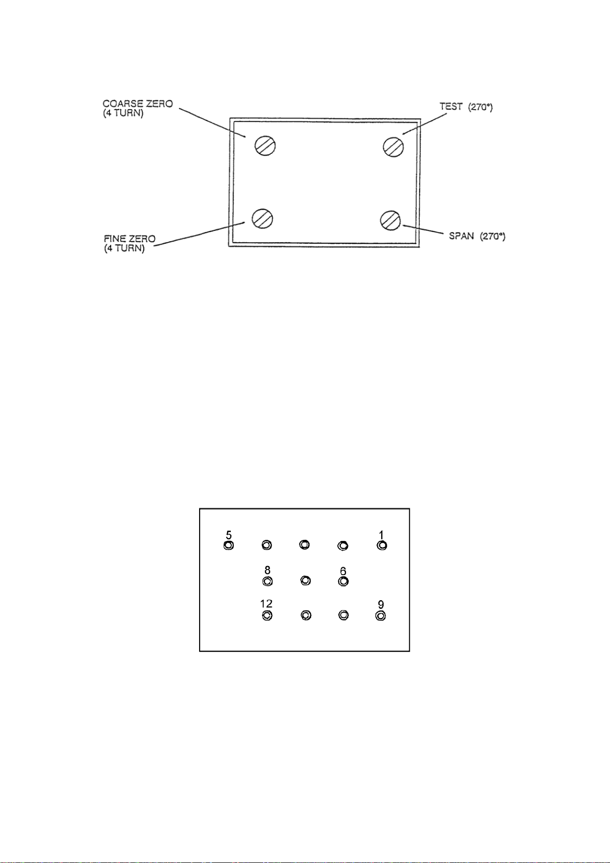
Housed within the amplifier module are the bridge balance potentiometers, gain setting potentiometer and
bridge test potentiometer along with the range and decimal point coding resistors. The whole is potted in
silicon rubber within a plastic shell.
The amplifier operates from supplies of a +/- 10v and a constant current of 20mA which is delivered to the
bridge via the zero network. The output voltage from the amplifier is fed to the internal circuitry of the ETS.
SPECIFICATIONS
Accuracy: See calibration certificate supplied with transducer.
Amplifier Output: 1.0000 volts Full Scale Defection for N∙m.
1.3558 volts Full Scale Defection for lbf∙ft.
1.1299 volts Full Scale Defection for lbf∙in.
0.9807 volts Full Scale Defection for Kgf∙m
Amplifier Power Requirement: +/- 10v D.C. Regulated.
Constant Current: 20mA +/- .01 mA
Operating Temperature Range: -10ºC - +50ºC
Storage Temperature Range: -20ºC - +70ºC
Temperature Co-efficient: <+/- 0.01%/ºC. Full Scale Defection on zero
<+/- 0.03%/ºC. Full Scale Defection on span
Maximum Working Overload: 120% of rated capacity
Absolute Maximum Torsion: 150% of rated capacity
NOTE: If equipment is used in a manner not specified by the manufacturer, the protection
provided by the equipment could be impaired.

3
AMPLIFIER AND TRANSDUCER CONNECTIONS
Amplifier
Pin 1: Constant current 20mA. input to amplifier.
Pin 2: +10 volt supply.
Pin 3: Amplifier output.
Pin 4: Select decimal point output to ETS.
Pin 5: 0v common, (Connected to Pin F of Transducer via Transducer lead).
Pin 6: Input from Strain Gauge Bridge, (Connected to Pin A of Transducer via Transducer lead).
Pin 7: Select Range output to ETS.
Pin 8: Input from Strain Gauge Bridge, (Connected to Pin B of Transducer via Transducer lead).
Pin 9: -10 volt supply.
Pin 10: Test switch input, Shorted to Pin 11 when Test button pressed.
Pin 11: Supply to Bridge from amplifier, (Connected to Pin D of Transducer via Transducer lead).
Pin 12: Supply to Bridge from amplifier, (Connected to Pin C of Transducer via Transducer lead).
Pin 13: Not Used.

4
Amplifier Controls
The adjustments available are as follows:
Fine Zero: To remove any temperature drift effect or non-zero reading.
Coarse Zero: Used for initial bridge balancing, this potentiometer is covered by the label and should not
need adjustment.
Test: When the TEST switch on the ETS back panel is pushed and held in, the ETS display should
read the full scale capacity to which the transducer has been calibrated. This is only for
indication purposes only and not a calibration check. This potentiometer is covered by the
label and should only need adjustment if the span potentiometer is adjusted.
Span: This potentiometer is used to calibrate the amplifier to the transducer when the full scale
Torque is applied to the transducer. This potentiometer is covered by a green tamper proof
label and should only need adjustment if recalibrating the transducer.
Amplifier PIN Layout
TOP
TOP
BACK VIEW

5
Annular Torque Transducer Wiring Diagram
NOTE: Colours in brackets refer to transducers pre August 2000.
Resistance Between Terminals
A to F
350 OHMS
B to F
350 OHMS
C to F
700 OHMS
D to F
700 OHMS
C to D
1400 OHMS
Bridge Signals
A
Signal Out
B
Signal Out
C and D
Positive Excitation
F
Negative Excitation

6
ANNULAR TRANSDUCER TO PNEUTORQUE® CONVERSION
CHART
Pneutorque®
Model
Output Torque
of Pneutorque®
Annular
Transducer
Capacity
Part Number
PT1
500 lbf∙ft
680 N∙m
1000 lbf∙ft
1000 N∙m
50071.ETS
50070.ETS
PT1A
900 lbf∙ft
1200 N∙m
1000 lbf∙ft
1500 N∙m
50071.ETS
50072.ETS2
PT2
1250 lbf∙ft
1700 N∙m
PT5
2500 lbf∙ft
3400 N∙m
2500 lbf∙ft
2500 N∙m
50073.ETS
50074.ETS
PT6
2500 lbf∙ft
3400 N∙m
PT7
4500 lbf∙ft
6000 N∙m
5000 lbf∙ft
5000 N∙m
50075.ETS
50076.ETS
PT9
7000 lbf∙ft
9500 N∙m
7000 lbf∙ft
10000 N∙m
50077.ETS2
50078.ETS
PT11
14700 lbf∙ft
20000 N∙m
10000 lbf∙ft
10000 N∙m
50082.ETS
50081.ETS
PT13
35000 lbf∙ft
47000 N∙m
50000 lbf∙ft
50000 N∙m
50080.ETS
50085.ETS
PT14
73500 lbf∙ft
100000 N∙m
100000 lbf∙ft
100000 N∙m
50154.ETS
50143.ETS
TORQUE TIGHTENING FOR REACTION PLATE BOLTS
Bolt Size
lb∙ft
N∙m
2 BA
7
9
¼ BSF
14
19
⅜ BSF
55
75
M 5
9
12
M 6
13
17.5
M 8
32
43
M 10
61
83
M 12
115
155
M 16
230
310

7
TRANSDUCER LEAD FOR ETS (Not Included)
Cable Connectors
A
Red (White)
B
Blue (Green)
C
Green (Red)
D
Yellow
E
-
F
Black (Blue)
NOTE: Colours in brackets refer to transducer leads pre August 2000.
Free Socket viewed
from cable end
Free Plug viewed
from cable end
FREE SOCKET
FREE PLUG

8
APPLICATION OF ANNULAR TRANSDUCERS ON
HANDTORQUETM GEARBOXES
To appreciate the operation of an Annular Transducer on a HandtorqueTM gear box, users need to be aware
of the following:
TORQUE ON TRANSDUCER (T reaction) = OUTPUT SQUARE DRIVE TORQUE (T output) - INPUT
TORQUE (T input)
The reason for this is that the annular transducer measures the reaction torque, not the applied torque and
part of the reaction torque is taken by the operator when the input to the multiplier is loaded
For the HandtorqueTM gearbox shown below there are three external torques applied.
1. The torque applied by the operator through the torque wrench.
( T input = F in x L in )
2. The torque applied to the annulus by the reaction force acting on the reaction plate.
(T reaction = Fr x Lr )
3. The resistive torque of the fastener applied to the gearbox through the drive square.
(T output)
This phenomenon only exists while the multiplier input is being loaded, so if an Anti Wind-up Ratchet is
used, measured torque will equal output torque when the input toqrue has been released.

OPERATOR’S MANUAL
ANNULAR TORQUE TRANSDUCER AND AMPLIFIER
FOR USE WITH ELECTRONIC TRANSDUCER SYSTEM (E.T.S)
Part Number 34147 | Issue 4 | Original Instructions (English)
NORBAR TORQUE TOOLS LTD
Beaumont Road, Banbury,
Oxfordshire, OX16 1XJ
UNITED KINGDOM
Tel + 44 (0)1295 270333
Email enquir[email protected]
NORBAR TORQUE TOOLS PTY LTD
45–47 Raglan Avenue, Edwardstown,
SA 5039
AUSTRALIA
Tel + 61 (0)8 8292 9777
Email enquir[email protected]
NORBAR TORQUE TOOLS INC
36400 Biltmore Place, Willoughby,
Ohio, 44094
USA
Tel + 1 866 667 2279
Email inquir[email protected]
NORBAR TORQUE TOOLS (NZ) LTD
B3/269A Mt Smart Road
Onehunga, Auckland 1061
NEW ZEALAND
Tel + 64 9579 8653
Email [email protected].au
NORBAR TORQUE TOOLS PTE LTD
194 Pandan Loop
#07-20 Pantech Business Hub
SINGAPORE 128383
Tel + 65 6841 1371
Email singapore@norbar.com.au
NORBAR TORQUE TOOLS (SHANGHAI) LTD
E Building–5F, no. 1618 Yishan Road,
Minhang District, Shanghai
CHINA 201103
Tel + 86 21 6145 0368
Email sales@norbar.com.cn
NORBAR TORQUE TOOLS INDIA PVT. LTD
Plot No A-168, Khairne Industrial Area,
Thane Belapur Road, Mahape,
Navi Mumbai – 400 709
INDIA
Tel + 91 22 2778 8480
Email enquir[email protected]
www.norbar.com
© Norbar Torque Tools Ltd 2014
This manual suits for next models
9
Table of contents
Popular Transducer manuals by other brands

Simrad
Simrad 38-200 COMBI C - REV D datasheet

FTS
FTS SDI-PT-KEL user manual

HBK
HBK T210 Mounting instructions

Veris
Veris EP3 Series installation guide

Mianyang Weibo Electronic
Mianyang Weibo Electronic WBV415S01 user manual

S+S Regeltechnik
S+S Regeltechnik PREMASGARD 1110 Operating Instructions, Mounting & Installation