Oppo BDT-101CI User guide

INSTALLER MANUAL
READ CAREFULLY BEFORE PRODUCT INSTALLATION
Blu-ray Disc Player BDT-101CI
i
Table of Contents
Optional Module Installation..................................................... 1
Removing the Top Cover.............................................................................................1
Installing the Top Cover..............................................................................................2
Removing the Stereo Audio Outputs Module.............................................................2
Installing the 7.1ch Analog Audio Output Module .....................................................4
Installing the Additional HDMI Output Module ..........................................................7
Installing the HDBaseT Output Module....................................................................12
Installing the Rack Mount Kit...................................................................................15
Common Connection Methods................................................ 17
Connecting to a TV via HDMI....................................................................................17
Connecting to an A/V Receiver via HDMI.................................................................18
Connecting to a TV and A/V Receiver via Dual HDMI..............................................19
Connecting to Two TVs via HDMI.............................................................................20
Connecting to an A/V Receiver or Amplifier via Analog Outputs............................21
Connecting to an A/V Receiver or Amplifier via S/PDIF (Coaxial / Optical)............22
Connecting to the Internet .......................................................................................23
Internet connection through Ethernet cable...................................................................................23
Internet connection through wireless adaptor................................................................................24
External IR (Infrared Remote) Installation...............................................................25
RS232 Control............................................................................................................25
SETUP MENU OPTIONS........................................................... 26
Using the Setup Menu System..................................................................................26
Playback Setup..........................................................................................................29
Video Output Setup...................................................................................................32
Picture Adjustment.........................................................................................................................35
Select the Best Output Resolution.................................................................................................37
Determine the Display Aspect Ratio..............................................................................................39
Audio Output Setup...................................................................................................40
Audio Signal Reference Chart.......................................................................................................44
Recommended Audio Format Options ..........................................................................................45
Audio Processing Setup............................................................................................47
Speaker Configuration...................................................................................................................49
Device Setup .............................................................................................................53
Network Setup...........................................................................................................57
Specifications.......................................................................... 61
User Manual Updates Online .................................................. 61
Language Code List................................................................. 62
RS-232 Control Protocol.......................................................... 63
1
Optional Module Installation
The BDT-101CI features a modular design, and can be customized to fit the specific requirement of each
installation. When you order the BDT-101CI you can specify to have the optional modules pre-installed. You
can also order the optional modules and perform the installation yourself. The following sections describe the
installation procedures for some common module types.
Cautions shall be taken in order to avoid injury to yourself and damage to the products.
Note
To avoid the possibility of electric shock, disconnect the power and other equipment before
installation.
Wear protective gloves during installation to avoid possible cuts from sharp metal edges.
Circuit Boards are subject to electrostatic damage. Wear an ESD wrist strap that grounds you
during work.
Tools required:
No.2 Phillips screwdriver
Hex socket screwdriver
Anti-static protective glove
ESD wrist strap
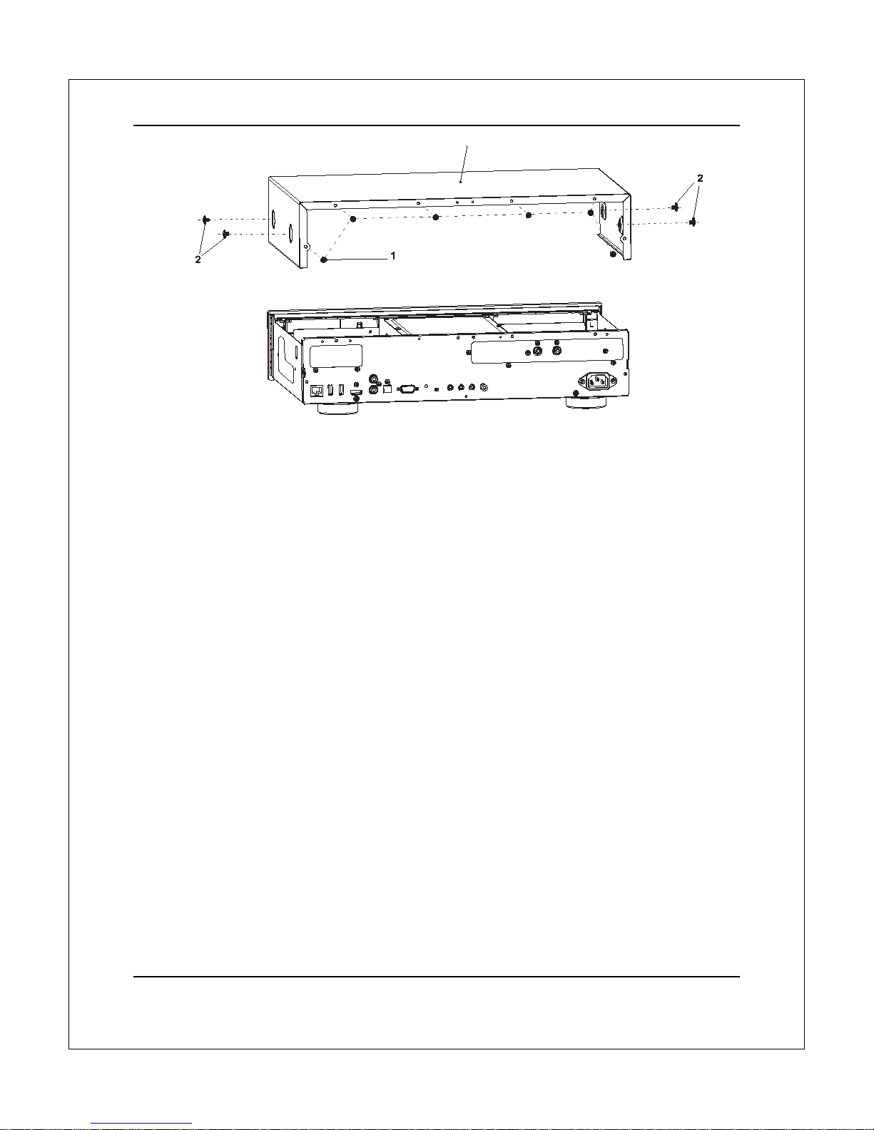
Removing the Top Cover
In order to perform a module installation, the top cover of the player must be removed first. The following steps
illustrate how to remove the top cover.
Step 1: Remove the 6 screws that secure the top cover to the back panel of the player. Save the
screws for installing the top cover later.
Step 2: Remove the 4 screws on the sides of the player, 2 on each side. Save the screws for
installing the top cover later.
Step 3: Lift the top cover from the back. Tilt it upwards and then slide it towards the back in order to
release it from the front panel. Remove the top cover.
OPTIONAL MODULE INSTALLATION
2
Installing the Top Cover
After a module installation, the top cover of the player must be installed back before the player can be put into
use. The following steps illustrate how to install the top cover.
Step 1: Place the top cover to its designated position. Align the front edge of the top cover with the
back of the front panel, tilt the top cover so its back side is slightly above the front side, and slide
the top cover into its position.
Step 2: Install the 6 screws that secure the top cover to the back panel of the player.
Step 3: Install the 4 screws on the sides of the player, 2 on each side.
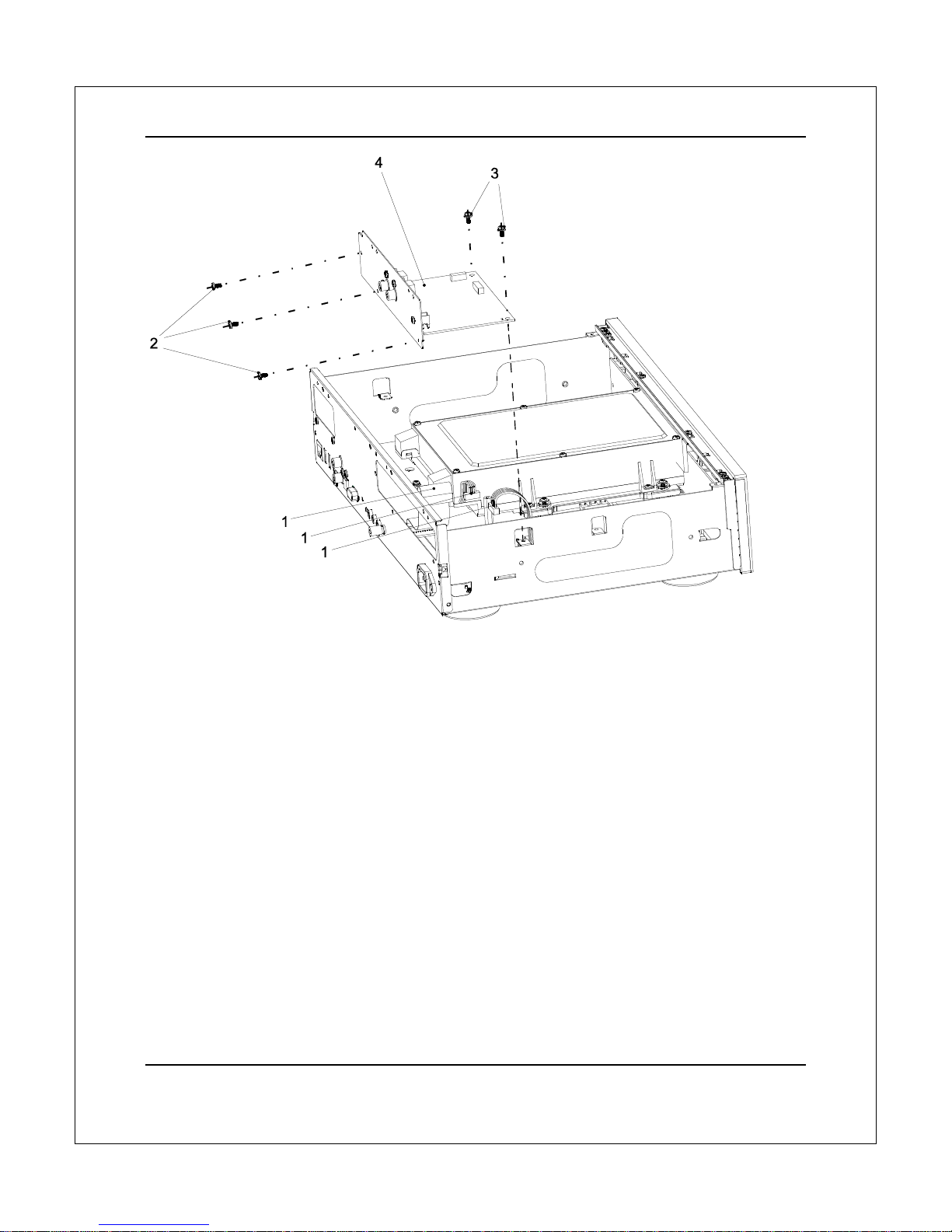
Removing the Stereo Audio Outputs Module
The BDT-101CI can accommodate one audio output module. In its basic configuration, the stereo audio
output module is pre-installed. In order to replace this module with an optional audio output module, you need
to remove the stereo audio output module first. Please follow these steps:
Step 1: Unplug the 3 cables from the stereo audio output module. When unplugging the ribbon
cables, pay attention not to damage the cable. Only the cable ends that are connected to the stereo
audio output module need to be unplugged. The other ends that are connected to the main board
or power supply board do not need to be unplugged.
Step 2: Remove the 3 screws that secure the stereo audio output module to the back panel.
Step 3: Remove the 2 screws that secure the stereo audio output module to the bottom plate.
Step 4: Lift and remove the stereo audio output module.
Other types of audio output modules can be removed using a similar procedure.
3
OPTIONAL MODULE INSTALLATION
3
OPTI
O
Inst
a
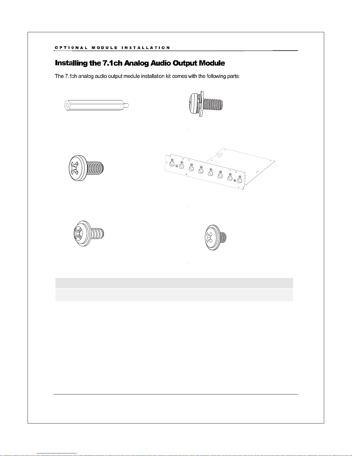
The 7.1
c
A
0
1
A0
3
A0
5
Not
e
A05
a
O
NAL MO
a
lling the
c
h analog au
d
1
: board rise
r
3
: screw, 3pc
5
: chassis scr
e
e
:
a
nd
A
06 are
s
DULE IN
S
7.1ch A
n
d
io output m
o
r
, 1pc
s
e
w, 2pcs
s
pare screw
s
S
TALLAT
n
alog A
u
o
dule installati
s
for installin
g
ION
4
u
dio Out
p
on kit comes
A
A
A
g
the top co
v
p
ut Mod
u
with the follo
w
A
02: screw
w
A
04: 7.1ch
a
A
06: chassis
s
v
er.
u
le
w
ing parts:
w
ith washer,
a
nalog audio
s
crew, 2pcs
4pcs
output mod
u
u
le

OPTIONAL MODULE INSTALLATION
5
Step 1: Remove the existing audio output module.
Step 2: Install the board riser (A01) into the screw hole on the bottom plate located between the
disc loader and the power supply board. Tighten with a hex socket screwdriver.

OPTIONAL MODULE INSTALLATION
6
Step 3: Place the 7.1ch analog audio output module into position. Align the screw mounting holes
properly.
Step 4: Install the 4 screws with washer (A02) to secure the 7.1ch analog audio output module to
the bottom plate.
Step 5: Install the 3 screws (A03) to secure the 7.1ch analog audio output module to the back
panel.
Step 6: Plug in the 3 cables that connect the 7.1ch analog audio output module to the main board
and the power supply board. When connecting the ribbon cable, make sure that the end is aligned
properly with the socket, and insert straightly into the socket.

OPTIONAL MODULE INSTALLATION
7
Installing the Additional HDMI Output Module
The additional HDMI output module installation kit comes with the following parts:
H01: cable bundle, 1pc H02: ribbon cable, 1pc
H03: board riser, 1pc
H04: screw, 4pcs H05: screw with washer, 2pcs
H06: HDMI output back plate H07: HDMI output board
H08: chassis screw, 2pcs H09: chassis screw, 2pcs
Note
H08 and H09 are spare screws for installing the top cover.

OPTIONAL MODULE INSTALLATION
8
Step 1: Remove any existing video output module. If no video output module is pre-installed, take
out the dummy back plate for the video output module by removing the 2 screws that secures it to
the player’s back panel.
Other manuals for BDT-101CI
1
Table of contents
Other Oppo Blu-ray Player manuals


 User manual")


