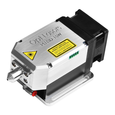
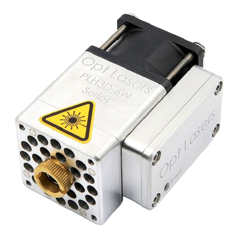
Opt Lasers PLH3D-XT-50 User manual

Thank You for Your Purchase!
Thank you for purchasing the Opt Lasers’ PLH3D-XT-50 laser head. The XT-50 laser
engraver and cutter from the PLH3D Series is a versatile and powerful tool designed for
a wide range of applications. This laser head is capable of laser engraving and cutting
various materials, including plastics, leather, wood, cardboard, textiles, and fibreglass
as well as laser engraving anodized aluminum, stainless steel, tool steel and Titanium.
Similar to its predecessor, the XF+, the XT-50 can be easily integrated and controlled by
CNC machines and 3D printers, making it a flexible solution for many manufacturing
processes. Its universal mountability allows it to replace CO2 lasers in numerous
applications, providing a compact and energy-efficient alternative as XT-50 is 4 times
more energy efficient than a CO2 laser tube (not counting the CO2 laser chiller which
lowers a CO2 laser’s energy efficiency even further).
One of the notable features of the XT-50 is its compact and lightweight design,
eliminating the need for additional cooling systems. The laser head's body serves a dual
purpose by directing air from the fan to remove smoke and functioning as an effective
heat sink. With its housing crafted from machined Aluminum, XT-50 remains lightweight
while effectively dissipating heat from the laser diode, ensuring a longer operational
lifespan even at high power settings.
To safeguard the semiconductor laser and maintain its longevity, the XT-50 incorporates
a built-in overheating protection device. When the laser diode’s housing temperature
surpasses 45°C (113°F), the laser head automatically shuts off, resuming operation
once it reaches 40°C (103°F). Furthermore, its professional high-speed laser driver is

integrated directly into the laser head, enabling higher maximum modulation
frequencies. High power modulation (up to 100 kHz) ensures the high speed of the
XT-50 engraving laser, even for the most sophisticated patterns.
Equipped with a special advanced optical system, the XT-50 provides 4k Ultra-HD
precision engraving and cutting capabilities. This makes XT-50 the most precise
high-power laser head in the world. Unlike the XF+, the XT-50 has an adjustable and
square focused beam spot.
For optimal engraving performance in various applications, we recommend calibrating
the working distance in two runs on the first launch.
The XT-50 excels in working with different types of materials. It can engrave and create
2D and 3D images on various kinds of wood, including Birch and Pine plywood, Balsa,
hardwood, and MDF. Being based on the blue laser technology makes it the best and
most energy-efficient solution for laser engraving wood. Additionally, it can cut
low-density wood with ease. Textiles such as white cotton, denim, felt, Cordura™, 2 and
3-way stretch fabrics, and many types of nylon can be cut without penetrating the
protective layer, as commonly found in the embroidery industry. Furthermore, XT-50 can
laser mark the majority of fabrics and textiles.
The blue light emitted by the XT-50 enables engraving on metals such as black
anodized aluminum and wrought iron. It also excels in engraving (and marking) titanium
and stainless steel. When it comes to plastic cutting, the XT-50 is capable of working
with ABS, acrylics, polypropylene, polyamides, as well as latex, neoprene, and other
rubber compositions. Lastly, it is a perfect solution for cutting and engraving various
types of leather, especially brown (vegetable-tanned) full-grain leather and black
full-grain leather.
With its wide range of capabilities and robust features, the XT-50 laser engraver and
cutter from the PLH3D Series offers exceptional performance and versatility for various
applications, making it a valuable tool for industrial, professional, and hobbyist use.

Technical Specifications
Performance Parameter
PLH3D-XT-50
Laser Diode’s Optical Power1
[W]
6
Optical Power Density
[kW/cm²]
2500
Resolution
[µm (DPI)]
50 (>500)
Wavelength
[nm]
445 ± 10
Maximum Power Consumption
[W]
30
Control Signal Input
[V]
Analog - 0-5 / 0-10
PWM - 0-5 / 0-10 / 0-24
Power Supply Voltage
[V]
12-24
Dimensions
[cm³ (inch³)]
4.0 x 5.5 x 14.0
(1.6 x 1.7 x 5.51)
Weight
[kg (lb)]
0.370
(0.816)
Fan Flow Rate
[m3/ h (CFM)]
43 (25)
Fan Noise
[dBA]
58
Operating (Ambient) Temperature Range
[°C (°F)]
0-45
(32-113)
Mounting Hole Pattern
4 Holes,
24 mm by 15 mm
(0.94 in. by 0.59 in.)
Mounting Hole Type
M3 x 0.5 x 4.5 mm

Laser Safety
Only a person with specialized training and appropriate laser safety knowledge can
use and maintain the laser head. The laser head operator must be aware of laser
radiation hazard.
While the laser head is operating protection Laser Glasses designed for 190 – 540
nm (OD 7+) should be used. Make sure that all personnel in the same room wear
protection glasses.
Eye exposure to the direct or diffusely reflected laser beam is a hazard. The laser
head beam may cause permanent eye damage.
Skin exposure to the laser beam is a hazard. The laser beam may cause serious skin
burns. A laser beam may easily burn cloth.
It is possible to get a serious injury while using this product or being in the vicinity
of an individual using it. Improper use of the laser head can result in injury or death.
Flammable substances exposure to the laser beam may pose a fire hazard. The laser
head operation in an explosive atmosphere may be dangerous. The working area
must be well-ventilated. During the operation laser beam may ignite gases or
flammable liquids.
Before making any adjustments, changing accessories, or performing maintenance,
the laser should be powered off and disconnected from the power supply and CNC
main board.
The laser head must be properly mounted to a rigid body such that it cannot be
moved unintentionally. An unintentional move of the laser head is dangerous.
The unauthorized personnel must have no access to the system into which the laser
head is integrated. The laser head must be stored out of the reach of children.
Untrained persons are not allowed to operate, maintain and observe the operation of
the laser head.
Specular reflection materials should not be placed in front of the operating laser
head. Remember, a diffused reflection of the laser beam is uncontrolled and may
pose a hazard to an eye.
Appropriate shielding should be used around the system into which the laser head
is integrated. The system in which the laser head is used must be equipped with a
key switch and safety interlock.

Electrical Inputs
Pin Descriptions:
1. Mod Input #1 ANG
Modulation input #1 accepts analog or Pulse-Width Modulation (PWM) signals. The
operating range of modulation input #1 is 0 - 5 V. If it is connected to a signal with a
slightly higher voltage, e.g. 0 - 10 V, only the 0 - 5 V part of the signal will affect the laser
power. The voltage connected to this input should not exceed 10 V.
NB: Do not connect control signal cables simultaneously to the Mod Input #1 ANG pin
and Mod Input #2 PWM.
NB2: Mod Input #1 ANG and Mod Input #2 PWM pins share a common ground in the
form of pin #3 (Mod Input GND).

2. Mod Input #2 PWM
Modulation Input #2 accepts PWM signals whose voltage in the high state (interpreted
as laser on) should be a minimum of 3 V. Examples of compatible control signal ranges
are: 0 - 5 V, 0 - 10 V and 0 - 24 V.
In the case of PWM control, we recommend using a frequency of base frequency of
5,000 - 10,000 Hz. Although frequencies such as 1,000 Hz will also work, higher
frequencies usually produce better greyscale images. The signal fill percentage
corresponds to the laser power output percentage.
NB: Do not connect signal cables simultaneously to the Mod Input #1 ANG pin and Mod
Input #2 PWM.
NB2: Mod Input #1 ANG and Mod Input #2 PWM pins share a common ground in the
form of pin #3 (Mod Input GND).
NB3: For the voltage to be interpreted as a high state (laser on) it should be a minimum
of 3.0 V. Conversely, for it to be interpreted as a low state (laser off), it should not
exceed 1.0 V. The state between 1-3 V is not defined.
3. Mod Input GND
This is the ground (GND) common to the Mod Input #1 ANG and Mod Input #2 PWM
pins.
4. GND
This is the ground (GND), for the laser head’s power supply (Vcc pin).
5. Vcc
This is the power supply (Vcc) to the laser head, which should be (for XF+ and
XT-Series laser heads) in the 12-24 V range. At a 12 V power supply, the current should
be a minimum of 2.5 A, and with a 24 V power supply, it should be ≥1.25 A.

Working Distance
The working distance (WD) of the PLH3D-XT-50 laser head should be set to 60 mm
(2.36 inch) between the bottom face of the laser head and the material processed as
shown below.
Working Distance Calibration
The working distance of the XT-50 laser head should be calibrated with high precision
once the initial working distance of 60 mm is set. This only is required to be done once,
unless the laser head was unassembled from the CNC machine and put back on.
An example of calibration (with an XF+ laser head) is shown in this video:
https://youtu.be/PP30pUkwDrE
The process consists of engraving lines on the material at different working heights
around the standard working distance. This is followed by moving the working distance
to a height at which the engraved lines are the thinnest.

For the XT-50 we highly recommend that two calibration runs are carried out. The first
run should be done ± 5 mm around 60 mm WD (with 1 mm iterations).
The working height at which the engraved lines are the thinnest is the distance to which
you should move your laser head (ie. at which you should use it) and which will give you
the best results.
The second calibration run should be done with an accuracy of 0.1 mm (in 0.1 mm
iterations) around the best WD established during the first calibration run. Some users
calibrate the XT-50 with even greater accuracy, e.g. 0.02 mm during a third calibration
run.
NB: Most customers perform the working distance calibration process on plywood.
Better results can be obtained on black anodised aluminium (but then the
engraved aluminium should be tilted by a small angle, e.g. 4-7°). However, the best
calibration results can be achieved by marking a microscope slide, painted with a black
spray before the procedure.
NB2: The beam profile of the XT-50 (and XT-10) is always symmetrical.

High-Pressure Air Assist Nozzle Accessory Usage
The High-Pressure Air Assist Nozzle (HP Nozzle) can be installed on the XT-50 laser
head by simply sliding the nozzle cap on the lens sleeve and tightening the nozzle’s
position with the 4 provided screws.
For XT-50, the nozzle should not be placed higher than the oblong line on the XT-50’s
lens sleeve. On the other side, the HP Nozzle should ideally be placed approximately
2-3 mm above the material being processed.
Incorrect High-Pressure Air Assist Nozzle Installation Symptoms

Case 1 - Nozzle Too High
If the HP Nozzle is installed too high up, or it is not leveled properly, part of the laser
beam will be clipped. This looks similar to the pictures below, depending on the severity
of the issue:
This can result in a ghost image of the laser dot, which:
- will lower the laser power that arrives where you want to use it;
- depending on the exact setup and the material used, it may even engrave a copy
of the image/design on a side.

Even if you don’t have a ghost beam image, an improperly installed High-Pressure Air
Assist Nozzle may result in beam clipping.
The picture below shows what the XT-50’s beam profile should look like (at a distance
far away from its working distance) when it is installed correctly.

On the other hand, the two following pictures below show how the beam looks like if it is
clipped (incorrect).
Case 2 - Nozzle Too Low
If the HP Nozzle is installed too low down, the beam will focus inside the nozzle. This
means that you will not get the highest optical power density:
- It will lower the speed at which your laser head can laser engrave and laser cut
- You will not be able to reach a small enough beam spot required to do Ultra HD
resolution laser engraving and laser cutting
In addition, it may also result in a ghost image.

Recommended Usage Depending on the Application
Case 1 - Ultra HD Laser Engraving and Laser Cutting Thin Materials
For Ultra HD laser engraving as well as laser cutting thin materials, we recommend
placing the bottom tip of the HP nozzle at 58 mm from the bottom face of the laser
head. As a result, the tip of the nozzle is 2 mm above the material being laser cut or
laser engraved.

Case 2 - Thick Line Engraving
XT-50 laser heads’ adjustable square beam spot allows you to laser engrave with
different laser dot thicknesses. This introduces the possibility of rapidly engraving with a
single thick curve or line by using an offset.
In this case, the High-Pressure Air Assist Nozzle should also be placed in the same
fashion as in Case 1, ie. so that the bottom tip of the HP nozzle is 58 mm (2.28 inches)
from the bottom face of the laser head.
However, you move the laser head higher up than usual. This can be for example 9 mm
(0.354 inch) above the working distance established during the WD calibration. And the
distance between the material being processed and the bottom face of the laser head is
e.g. 69 mm (2.72 inches).

Case 3 - Thick Materials Cutting
For laser cutting thick materials, the High-Pressure Air Assist Nozzle should be closer to
the laser head. Effectively, the bottom tip of the nozzle should be 55 mm from the
bottom face of the laser head as shown above.
Then you cut the material layer by layer. It is a good practice to find the speed and laser
power corresponding to cutting through ~1 mm of the material in a single pass - and
then lowering the laser head down 1 mm after each pass. In this manner, the beam
always focuses at the point where the laser beam needs to cut the material, speeding
up the process.
If you laser cut materials thicker than 5-6 mm, you should then stop changing the
working distance ideally after the 5th (HP nozzle 2 mm above the material) pass or 6th

pass (HP nozzle 1 mm above the material) so that the nozzle does not collide with the
material. This is depicted below.
Suitable Compressor
Any compressor will be suitable for supplying air to your High-Pressure Air Assist
Nozzle unit. However, because the appropriate flow rate must be determined
experimentally (for each different type of material to be processed), the desired results
might not be achieved with small compressor units. The higher the tank capacity and
the compressor performance, the higher the airflow that can pass through the air

nozzle. The work is also more comfortable with better compressor units (so that the
compressor will not turn on too often in order to refill the tank). We recommend a
compressor with a real airflow of 10-12 l/min and a tank capacity of at least 50 liters.
However, nothing prevents you from trying a smaller compressor. In fact, many of our
customers use small 5-liter tank capacity compressors that are available on Amazon for
approximately $60.
More importantly, your compressor should have a filter and an oil separator to avoid
blowing dirty air and/or oil droplets on the laser head’s lens, which can result in lens
damage.
Suitable Airflow
In our experience, the real airflow value of 10-15 l/min is the upper limit and completely
sufficient for most materials. We don't recommend going above 15-20 l/min. Above 20
l/min, the laser cutting speed of all materials decreases. We recommend a real airflow
value of 10 l/min as a starting point. Then you could experiment with using a slightly
higher airflow rate as the optimum airflow value differs from material to material.
In general, for laser cutting, you will typically find the optimum real airflow value to
be between 10-15 l/min.
For laser engraving, we recommend airflow values of 1-3 l/min.
As such, it is very useful to equip your compressor with a flowmeter.
Laser Head Lens Maintenance
The front lens of your laser head should ideally be cleaned every 100 working hours.
For the cleaning routine, you should use lab-grade 99.9% pure anhydrous isopropyl
alcohol (anhydrous IPA). Below are five examples:
-IPA Plus (EU)
-MG Chemicals (824) IPA (USA), also available on Amazon
-Dustronics IPA (Canada)
-Hexeal IPA (UK)
-MG Chemicals (824) IPA (Australia)
The example cleaning routine is shown in this video: https://youtu.be/MLzFjfEJGa4

The cleaning should be done in a delicate manner, enough to clean oil drops and dirt, but not
too strong to avoid damaging the lens coating.
m
NB: You should not use lens wipes, that are advertised for cleaning reading glasses and
microscopes. These typically have water content (around 30%) and often have additional
additives that can adversely interact with the lens coating. This results in smudges on and/or
damage to the lens coating.
NB2: You should also not use anything that is advertised as rubbing alcohol (it is typically ~70%
IPA and 30% water). Water may leave marks on the lens after drying so an anhydrous
(water-free) isopropyl alcohol (IPA) is the best for it.
Highly-Reflective Materials
Whenever you laser engrave a highly reflective material, you should tilt the material
slightly, introducing a small angle, e.g. 7°. This makes sure you do not have an issue
with the back-reflection to the laser diode and ensures the longevity of your laser head.
Table of contents
Other Opt Lasers Measuring Instrument manuals