Adash A3716 User manual

USER MANUAL
A3716, A3800
Online Monitoring System
Version: March 27, 2018

ADASH Ltd. A3716, A3800
ADASH Ltd., Czech Republic, tel.: +420 596 232 670, fax: +420 596 232 671, email: info@adash.cz
Next technical information you find on www.adash.com
2
Content:
Basic hardware explanatory notes ......................................................................... 4
The Adash DSP board.......................................................................................................4
4-20mA current loops and its industrial use .......................................................................4
Relay outputs.....................................................................................................................4
Latched relay .....................................................................................................................4
A3716 unit description ............................................................................................. 6
A3716 - Front panel ...........................................................................................................6
A3716 - Rear panel............................................................................................................7
A3716 sensor and tacho connection ...................................................................... 9
Acceleration sensor connection .........................................................................................9
Tacho trigger (speed probe) connection.............................................................................9
A3800 unit description ........................................................................................... 10
A3800 - Front panel .........................................................................................................10
A3800 - Bottom panel ......................................................................................................11
A3800 sensor and tacho connection .................................................................... 12
A3800 – Top panel ..........................................................................................................12
Acceleration sensor connection .......................................................................................13
Tacho trigger (speed probe) connection...........................................................................13
A3764 – 64 channel multiplexer ............................................................................ 14
Front panel ......................................................................................................................14
Rear panel.......................................................................................................................15
Wiring scheme.................................................................................................................16
Technical Specification ....................................................................................................16
ICP powering ...................................................................................................................16
A3716 IP address setting (the same for the A3800)............................................. 17
A3716 (A3800) as a stand alone computer ......................................................................17
Network remote access ...................................................................................................18
IP address setting ............................................................................................................18
Network for data transfer (the same for the A3800) ............................................ 20
Company network usage .................................................................................................20
Creating of your own network ..........................................................................................20
Connection test................................................................................................................21
Server software installation (the same for the A3800) ........................................ 22
Adash Server installation .................................................................................................23
DDS – online database and collecting of readings (the same for the A3800) ... 26
Online database creation .................................................................................................26
Measuring unit and database connection.........................................................................26
Start of the data collection ...............................................................................................27
Graph refresh time interval...............................................................................................28
Actual data reading..........................................................................................................29
Current loops and relays..................................................................................................29
Conditional measurements ..............................................................................................30
Temporary stop of readings .............................................................................................30
Advanced functions for A3716 (A3800) units ...................................................................31
A3716 (A3800) lock .........................................................................................................32
Updating DDS..................................................................................................................32
Adaptive algorithm for readings ........................................................................... 33
How does the algorithm work?.........................................................................................33

ADASH Ltd. A3716, A3800
ADASH Ltd., Czech Republic, tel.: +420 596 232 670, fax: +420 596 232 671, email: info@adash.cz
Next technical information you find on www.adash.com
3
Large dynamic readings processing.................................................................................33
Data saving example .......................................................................................................33
Variable settings of data collection ...................................................................... 35
Regulator section.............................................................................................................35
Examples.........................................................................................................................36
Time synchronization of A3716 (A3800)............................................................... 37
A3716 (A3800) Update............................................................................................ 38

ADASH Ltd. A3716, A3800
ADASH Ltd., Czech Republic, tel.: +420 596 232 670, fax: +420 596 232 671, email: info@adash.cz
Next technical information you find on www.adash.com
4
Basic hardware explanatory notes
We would like to explain a few terms in the beginning of this manual.
The Adash DSP board
The Adash DSP (Digital Signal Processing) board is the most important part of the instrument. The
special chip provides all necessary operations, which are required for achieving of 4 channel
synchronous data.
4-20mA current loops and its industrial use
For industrial process control instruments, analog 4–20 mA current loops are commonly used for
analog signaling, with 4 mA representing the lowest end of the range and 20 mA the highest. The key
advantages of the current loop are that the accuracy of the signal is not affected by voltage drop in the
interconnecting wiring, and that the loop can supply operating power to the device. Current loop
outputs of actual value are then used in control systems (PLC).
The current loops used in the A3716 are isolated from measuring circuits. They must be externally
powered (they use passive mode).
Relay outputs
Two relay initial states exists. Energized and de-energized. Energized relay is initially powered and its
internal connections are as seen on the picture below (NO-normally opened, NC-normally closed,
COM-common are standard electrical terms). De-energized relay is initially not powered. Internal
connections are seen on the pictures.
Latched relay
We describe it on example:
The factory initial state of the relay is de-energized (i.e. NC and COM is connected). The ISO RMS
(10-1000Hz) value is measured on the machine. When the RMS value will exceed 2 mm/s, then the
relay will switch on the red light in a control room. When the vibration value will decrease under the
2mm/s, then the relay will switch off the light.

ADASH Ltd. A3716, A3800
ADASH Ltd., Czech Republic, tel.: +420 596 232 670, fax: +420 596 232 671, email: info@adash.cz
Next technical information you find on www.adash.com
5
If the LATCH function is chosen, then the relay will not switch off the light when the vibration
decreases less than 2mm/s. The relay keeps the switch ON until it is manually switched off ( through
the use of REL–RST).

ADASH Ltd. A3716, A3800
ADASH Ltd., Czech Republic, tel.: +420 596 232 670, fax: +420 596 232 671, email: info@adash.cz
Next technical information you find on www.adash.com
6
A3716 unit description
A3716 - Front panel
Legend:
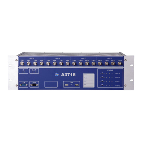
CH1 - CH16 BNC buffered outputs (A3716/3U only) allows connecting of portable vibration analyzer
and performing further analysis on required channel.
GRP A – GRP D. 16 channels are divided into 4 groups A,B,C,D. Each of them contains 4 channels,
which are measured by one Adash DSP 4channel board.
GRP A – GRP D status LEDs enables to monitor each DSP board. Three states can appear:
- OK, the measurement is running - green light blinks in 0.25sec time interval (four times per sec)
- OK-STANDBY, the measurement is stopped - green light blinks in 1 sec time interval
- ERROR - red light.
Reset button enables to reset each Adash DSP board ( A,B,C,D).
Power button runs the A3716 unit. There is a status LED as well.
VGA output allows connecting of monitor in case you use the A3716 as a 16 channel vibration
analyzer.
HDD status LED indicates the operation state of the hard drive.
Serial number of the A3716/3U is 6 digits number provided by Adash. If more A3716 unit is used, it
helps to recognize them in setting.
USB ports allows connecting of mouse and keyboard for control of the A3716 unit in case you use the
A3716 as a 16 channel vibration analyzer the USB ports.
Status LEDs for each channel informs about the operation state of appropriate channel. Green color
indicates good condition of the channel input, sensor and cable. Red color indicates error. In this case
you should check the sensor and cable. Otherwise contact your supplier of A3716 unit.A3716 - Rear
panel

ADASH Ltd. A3716, A3800
ADASH Ltd., Czech Republic, tel.: +420 596 232 670, fax: +420 596 232 671, email: info@adash.cz
Next technical information you find on www.adash.com
7
A3716 - Rear panel
Legend:
LOOP 1-16 outputs (A3716/3U only) contains 4 – 20 mA current outputs clamps.
REL 1-16 Relay outputs (A3716/3U only) contains relay clamps (NO,COM,NC).
PWR output (A3716/3U only) is the source of +5V/1A and +12V/1A voltage outputs. All GND
(grounds) clamps are shorted (connected together).
BINARY inputs (A3716/3U only) are logical inputs ( states 0 or 1)
B- Common negative pole

ADASH Ltd. A3716, A3800
ADASH Ltd., Czech Republic, tel.: +420 596 232 670, fax: +420 596 232 671, email: info@adash.cz
Next technical information you find on www.adash.com
8
B1...B8 – Isolated inputs 5-30V/4mA max. The level of voltage on each input defines the logical state.
Logical 0 - DC voltage 0-3V is required
Logical 1 - DC voltage 5-30V is required.
You should avoid the voltage in 3-5V range. The response of the circuit is unclear and unpredictable.
It may oscillate and accidentally change logical values.
REL - SYS - if the A3716 system is in correct operation then this system relay is energized (A3716/3U
only). In case of DSP board error or ICP error relay is deenergized.
REL - RST resets all latched relays (A3716/3U only).
R-: Common negative pole
R1 and R2: (DC voltage 5-30V/4mA max.)
When the voltage appears on R-R1 or R-R2 then all latched relays will be reset. You may have a
question: why two clamps are used (R1 and R2)? It enables to reset latched relays by two buttons
which could be in two places. E.g. one reset button is near of the A3716 and second reset button is in
the control room.
CH 1 – 16 AC inputs (ICP® powering available) for AC signals measurement, usually for vibration
measurements (acceleration sensor connected). Max. Peak/Peak voltage range is +/- 12 V.
DC 1 – 16 DC inputs for DC signal measurement (e.g. process values like temperature, pressure, flow
etc.). Max. voltage range is +/- 24V.
20V output, max.10mA. It is available for external powering of sensors. Use the minus pole from the
appropriate input.
TRIG A-D inputs are for trigger connection for GRP A-D (see front panel description).
+5V: power for tacho (speed) probe (max 100 mA)
NC: not connected
-: ground
+: trigger signal input
VGA output allows connecting monitor in case you use the A3716 as a 16 channel vibration analyzer.
It is shorted with the same output on the front panel.
USB ports allow connecting mouse and keyboard for control of the A3716 unit in case you use the
A3716 as a 16 channel vibration analyzer the USB ports. They are shorted with the USB ports on the
front panel.
Ethernet connection to LAN for setting and data transfer.
Main power switch for switch on/off of the A3716 unit.
Power supply socket requirements:
U: 100-240 V
I: 2,5-4,5A
f: 50-60 Hz

ADASH Ltd. A3716, A3800
ADASH Ltd., Czech Republic, tel.: +420 596 232 670, fax: +420 596 232 671, email: info@adash.cz
Next technical information you find on www.adash.com
9
A3716 sensor and tacho connection
Acceleration sensor connection
Commonly used sensor is the acceleration sensor 100 mV/g with ICP®.
Tacho trigger (speed probe) connection
Tacho trigger input range is + 10V.

ADASH Ltd. A3716, A3800
ADASH Ltd., Czech Republic, tel.: +420 596 232 670, fax: +420 596 232 671, email: info@adash.cz
Next technical information you find on www.adash.com
10
A3800 unit description
A3800 - Front panel
Legend:
Channels LEDs indicate on which channels the measurement is defined.
Green color … indicates good condition of the channel input, sensor and cable.
Flashing red color … indicates sensor or cable error.
Groups LEDs indicate which channel group is active for measurement.
Orange color … indicates active group.
Status LED indicates status of A3800 DSP board.
Fast flashing green color (four times per sec) … measurement is running.
Slow flashing green color (one time per sec) … waiting for measurement
Red color … DSP board error.
Ready LED indicates status of A3800 control board.
Green color … control board OK.
Red color … control board error.
HDD LED indicates r/w operation on HDD.
Red color … r/w operation in progress.
Power LED indicates power on of A3800 unit.
Green color … A3800 unit is power on.

ADASH Ltd. A3716, A3800
ADASH Ltd., Czech Republic, tel.: +420 596 232 670, fax: +420 596 232 671, email: info@adash.cz
Next technical information you find on www.adash.com
11
Reset button … press and hold for at least 5 seconds to reset control board.
Power button … press and hold for at least 5 seconds to switch ON/OFF A3800 unit.
A3800 - Bottom panel
Legend:
AUDIO I/O: socked for audio 3.5 jack.
USB 2.0: two USB ports.
ETHERNET: socked for Ethernet connection.
DISPLAY: HDMI display connection
POWER: socked for 12 V DC powering

ADASH Ltd. A3716, A3800
ADASH Ltd., Czech Republic, tel.: +420 596 232 670, fax: +420 596 232 671, email: info@adash.cz
Next technical information you find on www.adash.com
12
A3800 sensor and tacho connection
A3800 – Top panel
The connectors for connecting the sensors are located on the top panel. Connectors are divided into
groups A, B, C, D.
Group A: AC and DC channels 1 – 4, TACHO input 1.
Group B: AC and DC channels 5 – 8, TACHO input 2.
Group C: AC and DC channels 9 – 12, TACHO input 3.
Group D: AC and DC channels 13 – 16, TACHO input 4.
Input ranges:
AC input: +/- 12 V peak - peak
DC input: +/- 24 V or 4 – 20 mA
TACHO +10 V
In this picture you can see top panel with installed plug-ins.

ADASH Ltd. A3716, A3800
ADASH Ltd., Czech Republic, tel.: +420 596 232 670, fax: +420 596 232 671, email: info@adash.cz
Next technical information you find on www.adash.com
13
Acceleration sensor connection
Commonly used sensor is the acceleration sensor 100 mV/g with ICP®.
Tacho trigger (speed probe) connection
Tacho trigger input range is + 10V.

ADASH Ltd. A3716, A3800
ADASH Ltd., Czech Republic, tel.: +420 596 232 670, fax: +420 596 232 671, email: info@adash.cz
Next technical information you find on www.adash.com
14
A3764 – 64 channel multiplexer
A3764 multiplexer enables to use 64 AC channels. They are not synchronous. They are divided to 4
groups, each of them has 16 synchronous channels. These 4 groups are continuously switched
(multiplexed) to AC inputs and then the measurements are taken.
The A3716 and A3764 are connected by 16 signal wires and a the USB cable is used for transfer of
control signals.
Warning! The A3764 unit doesn't multiplex DC channels neither tacho inputs. It means the 16 DC
inputs and 4 tacho inputs are available for all 64 AC channels.
Front panel
The terminal blocks for wire connection and LED diodes are on the front panel.
LED description:
READY connected to A3716 (communication established)
1-16, 17-32, 33-48, 49-64 actually measured group
Terminal block view, channel order:
1 17 33 49 2 18 34 50 3 19 35 51 4 20 36 52
5 21 37 53 6 22 38 54 7 23 39 55 8 24 40 56
9 25 41 57 10 26 42 58 11 27 43 59 12 28 44 60
13 29 45 61 14 30 46 62 15 31 47 63 16 32 48 64

ADASH Ltd. A3716, A3800
ADASH Ltd., Czech Republic, tel.: +420 596 232 670, fax: +420 596 232 671, email: info@adash.cz
Next technical information you find on www.adash.com
15
Rear panel
The rear panel contains
output terminals for signals (OUT1 – OUT16),
USB B connector for communication,
terminal for powering of external equipments (+24V, +5V)
EURO socket with fuse for power supply.

ADASH Ltd. A3716, A3800
ADASH Ltd., Czech Republic, tel.: +420 596 232 670, fax: +420 596 232 671, email: info@adash.cz
Next technical information you find on www.adash.com
16
Wiring scheme
K1 – K4: Terminal blocks on A3764 side (MPX)
K5 – K12: Terminal blocks on A3716 side
Technical Specification
Powering: 85-265V AC / max 15W, protection 0.5A
Communicattion: USB
Inputs: 16x4 (64) with ICP powering 24V / 4mA
Outputs: 24V/300mA, 5V/100mA, 16x AC signal output
ICP powering
The A3764 unit contains own ICP power supplying. It means the ICP is not switched from A3716 unit.
All sensors are continuously powered and no additional settling time is required. All sensors
connected to A3764 inputs are always powered. It is not possible to power only some of them.
Unfortunately there's no way how to indicate an ICP error.
Optionally you can have an A3764 unit without ICP power supply. If you wish using sensors without
ICP, please specify the demand in your order.

ADASH Ltd. A3716, A3800
ADASH Ltd., Czech Republic, tel.: +420 596 232 670, fax: +420 596 232 671, email: info@adash.cz
Next technical information you find on www.adash.com
17
A3716 IP address setting (the same for the
A3800)
A3716 rack basically behaves as a local PC and it has its own IP address under which it is recognized
in your network. Most common situation is that you will need to change the A3716 rack IP address
because of your company’s policy.
Remark: If you don’t need to change the rack IP address, skip to chapter: Network for data transfer
There are two ways how the setup the IP address.
A3716 (A3800) as a stand alone computer
Windows OS is installed on A3716 measurement unit, so it is possible to connect with it like to a
common PC. Connect USB keyboard, mouse and monitor (VGA interface or HDMI interface). In
Windows login as a "remote" user with "remote" password and follow the chapter IP address setting.

ADASH Ltd. A3716, A3800
ADASH Ltd., Czech Republic, tel.: +420 596 232 670, fax: +420 596 232 671, email: info@adash.cz
Next technical information you find on www.adash.com
18
Network remote access
Second option how to change the A3716 IP address is to do it through network. Use the LAN cable
and connect the A3716 unit with PC (laptop) directly or through network (switch/HUB). IP address (set
during production) is written on the A3716 front panel. Use this IP address for remote desktop
connection. You can also use name of the unit, which is „A3716 – serial number“.
Remote desktop connection
Remote desktop connection is a program which allows to control another PC on the network from
your PC. From any PC on the network you can connect A3716 and change its setting (e.g. IP
address). Remote desktop program is a standard part of the Windows OS. You can find it under Start
button in Accessories folder.
It can be run also by "Search programs and files" in Start menu (Win7). Enter "mstsc" and press enter.
You can launch it also from "Run" window (press Win + R). Enter "mstsc" and press Enter.
New window Remote desktop connection appears then.
Enter the IP address or name of the computer into the Computer line and press Connect. Enter log in
parameters (factory settings are remote for username and password).
IP address setting
Press Win + R, enter "ncpa.cpl" and press Enter

ADASH Ltd. A3716, A3800
ADASH Ltd., Czech Republic, tel.: +420 596 232 670, fax: +420 596 232 671, email: info@adash.cz
Next technical information you find on www.adash.com
19
Network connection window will open. Select network adapter (usually Local area connection) press
right mouse button and select Properties.
Select "networks" tab in "This connection uses the following items" section.
Select "Protocol IP version 4 (TCP/IPv4)" and press „Properties“.
Select "General" tab and check the option "Use the following IP address". Enter the address which
your network manager gave you.
If you are changing the IP address using remote desktop, then after this change you have to create
the new connection ( connection with and old IP address will stop working).

ADASH Ltd. A3716, A3800
ADASH Ltd., Czech Republic, tel.: +420 596 232 670, fax: +420 596 232 671, email: info@adash.cz
Next technical information you find on www.adash.com
20
Network for data transfer (the same for the
A3800)
Server ( computer ):
- Determined for data collection and storage
- Ideally stand alone computer which is not used for any other purposes
- Continuous operation – pay attention on a proper components selection
- Connect ideally Gbit network with A3716 with DDS computer
- Suitable size of RAM and HDD
Software on a Server:
- Windows OS on the server
- DDS for tree management / data collection
- Program Data Manager as a service which handles data
Company network usage
In case of using company network, you need to assign static IP addresses to all components
(measuring units, server, users stations). We recommend to do it in cooperation with IT department.
Creating of your own network
If you decide to build your own computer network, then follow the following procedure. We always
recommend to create a network with cables, not wireless.
Other manuals for A3716
1
This manual suits for next models
1
Table of contents
Other Adash Measuring Instrument manuals
Adash
Adash A4900 - Vibrio M User manual
Adash
Adash A4900 - Vibrio M User manual
Adash
Adash VA5 Pro User manual

Adash
Adash 4900 Vibrio III User manual
Adash
Adash VIBRAMON 1 User manual
Adash
Adash VA4 Pro II User manual

Adash
Adash 4300 - VA3 User manual

Adash
Adash A4900 - Vibrio M User manual
Adash
Adash A4910 Lubri User manual
Adash
Adash A3900 II User manual
