Optica B-150 Series User manual

Model
B-150 series (B-151 / B-153 / B-155 / B-157 / B-159)
B-150 ALC series (B-151ALC / B-153ALC / B-155ALC / B-157ALC / B-159ALC)
B-150R-PL series (B-151R-PL / B-152R-PL / B-153R-PL / B-155R-PL / B-157R-PL / B-159R-PL)
B-150 Series
INSTRUCTION MANUAL
Ver. 12.1 2022

Page 2
1. Warning 3
2. Safety Information 3
3. Package content 4
3.1 B-151 / B-151ALC / B-151R-PL 4
3.2 B-152R-PL / B-153 / B-153ALC / B-153R-PL 4
3.3 B-155 / B-155ALC / B-155R-PL 5
3.4 B-157 / B-157ALC / B-157R-PL 5
3.5 B-159 / B-159ALC / B-159R-PL 6
4. Unpacking 7
5. Intended use 7
6. Symbols and conventions 7
7. Instrument description 8
7.1 B-151 / B-151R-PL 8
7.2 B-153 / B-155 / B-157 / B-159 / B-152R-PL / B-153R-PL / B-155R-PL / B-157R-PL / B-159R-PL 9
7.3 B-151ALC / B-153ALC / B-155ALC / B-157ALC / B-159ALC 10
8. Assembling 11
8.1 Assembling the microscope 11
8.2 Polarizing set (optional) 12
9. Use of the microscope 13
9.1 Light intensity adjustment 13
9.2 Use of ALC system 13
9.3 Coarse focus tension adjustment 13
9.4 Stage 13
9.5 Adjust the interpupillary distance 14
9.6 Diopter adjustment 14
9.7 Use of oil immersion objective 14
9.8 Aperture diaphragm 15
9.9 Use with rechargeable batteries 15
9.10 Use of the polarizer (optional) 15
10. Maintenance 16
11. Troubleshooting 17
Equipment disposal 18
Table of contents

Page 3
1. Warning
This microscope is a scientic precision instrument designed to last for many years with a minimum of maintenance. It
is built to high optical and mechanical standards and to withstand daily use. We remind you that this manual contains
important information on safety and maintenance, and that it must therefore be made accessible to the instrument users.
We decline any responsibility deriving from incorrect instrument use uses that does not comply with this manual.
2. Safety Information
Avoiding Electrical Shock
Before plugging in the power supply, make sure that the supplying voltage of your region matches with the operation voltage
of the equipment and that the lamp switch is in o position. Users should observe all safety regulations of the region. The
equipment has acquired the CE safety label. However, users have full responsibility to use this equipment safely. Please
follow the guidelines below, and read this manual in its entirety to ensure safe operation of the unit.

Page 4
3. Package content
3.1 B-151 / B-151ALC / B-151R-PL
3.2 B-152R-PL / B-153 / B-153ALC / B-153R-PL
① Frame
② Monocularobservationhead
③ Eyepiece
④ Tensionadjustmenttool
⑤ Objectives(4X/10X/40X)
⑥ Dustcover
⑦ Greenlter
⑧ Powersupply
③
④
⑤
⑥⑦
⑧
①
②
① Frame
② Monocularobservationhead
③ Eyepiece
④ Tensionadjustmenttool
⑤ Objectives
• B-152R-PL(4X/10X/40X)
• B-153(all)(4X/10X/40X/60X)
⑥ Dustcover
⑦ Greenlter
⑧ Powersupply
③
④
⑤
⑥⑦
⑧
①
②

Page 5
3.3 B-155 / B-155ALC / B-155R-PL
3.4 B-157 / B-157ALC / B-157R-PL
① Frame
② Monocularobservationhead
③ Eyepiece
④ Tensionadjustmenttool
⑤ Objectives(4X/10X/40X/100X)
⑥ Dustcover
⑦ Greenlter
⑧ Powersupply
⑨ Immersionoil
③
④
⑤
⑥⑦
⑧
①
②
⑨
① Frame
② Binocularobservationhead
③ Eyepiece
④ Tensionadjustmenttool
⑤ Objectives(4X/10X/40X/60X)
⑥ Dustcover
⑦ Greenlter
⑧ Powersupply
③
④
⑤
⑥⑦
①
②⑧

Page 6
3.5 B-159 / B-159ALC / B-159R-PL
① Frame
② Binocularobservationhead
③ Eyepiece
④ Tensionadjustmenttool
⑤ Objectives(4X/10X/40X/100X)
⑥ Dustcover
⑦ Greenlter
⑧ Powersupply
⑨ Immersionoil
③
④
⑤
⑥⑦
⑧
①
②
⑨

Page 7
4. Unpacking
The microscope is housed in a moulded Styrofoam container. Remove the tape from the edge of the container and lift the
top half of the container. Take some care to avoid that the optical items (objectives and eyepieces) fall out and get dam-
aged. Using both hands (one around the arm and one around the base), lift the microscope from the container and put it
on a stable desk.
Do not touch with bare hands optical surfaces such as lenses, lters or glasses. Traces of grease or other
residuals may deteriorate the nal image quality and corrode the optics surface in a short time.
5. Intended use
Standard models
For research and teaching use only. Not intended for any animal or human therapeutic or diagnostic use.
IVD Models
Also for diagnostic use, aimed at obtaining information on the physiological or pathological situation of the subject.
6. Symbols and conventions
The following chart is an illustrated glossary of the symbols that are used in this manual.
CAUTION
This symbol indicates a potential risk and alerts you to proceed with caution.
ELECTRICAL SHOCK
This symbol indicates a risk of electrical shock.

Page 8
COARSE
FOCUS KNOB
FINE FOCUS
KNOB
EYEPIECE
OBSERVATION
HEAD
MAIN SWITCH / INTENSITY
ADJUSTMENT DIAL
CONDENSER
STAGE
LED CHARGE
INDICATOR
(ONLY “R”
VERSION)
NOSEPIECE
OBJECTIVES
TENSION
ADJUSTMENT
COLLAR
STAGE CLIPS
7. Instrument description
7.1 B-151 / B-151R-PL

Page 9
TENSION
ADJUSTMENT
COLLAR
SLIDE
HOLDER
LED CHARGE
INDICATOR
(ONLY “R”
VERSION)
COARSE
FOCUS KNOB
FINE FOCUS
KNOB
STAGE
OBSERVATION HEAD
-) MONOCULAR (B-152 / B-153 / B-155)
-) BINOCULAR (B-157 / B-159)
CONDENSER
OBJECTIVES
MAIN SWITCH / INTENSITY
ADJUSTMENT DIAL
NOSEPIECE
X/Y MOVEMENT
KNOBS
EYEPIECE
7.2 B-153 / B-155 / B-157 / B-159 / B-152R-PL / B-153R-PL / B-155R-PL / B-157R-PL / B-159R-PL
Page 10
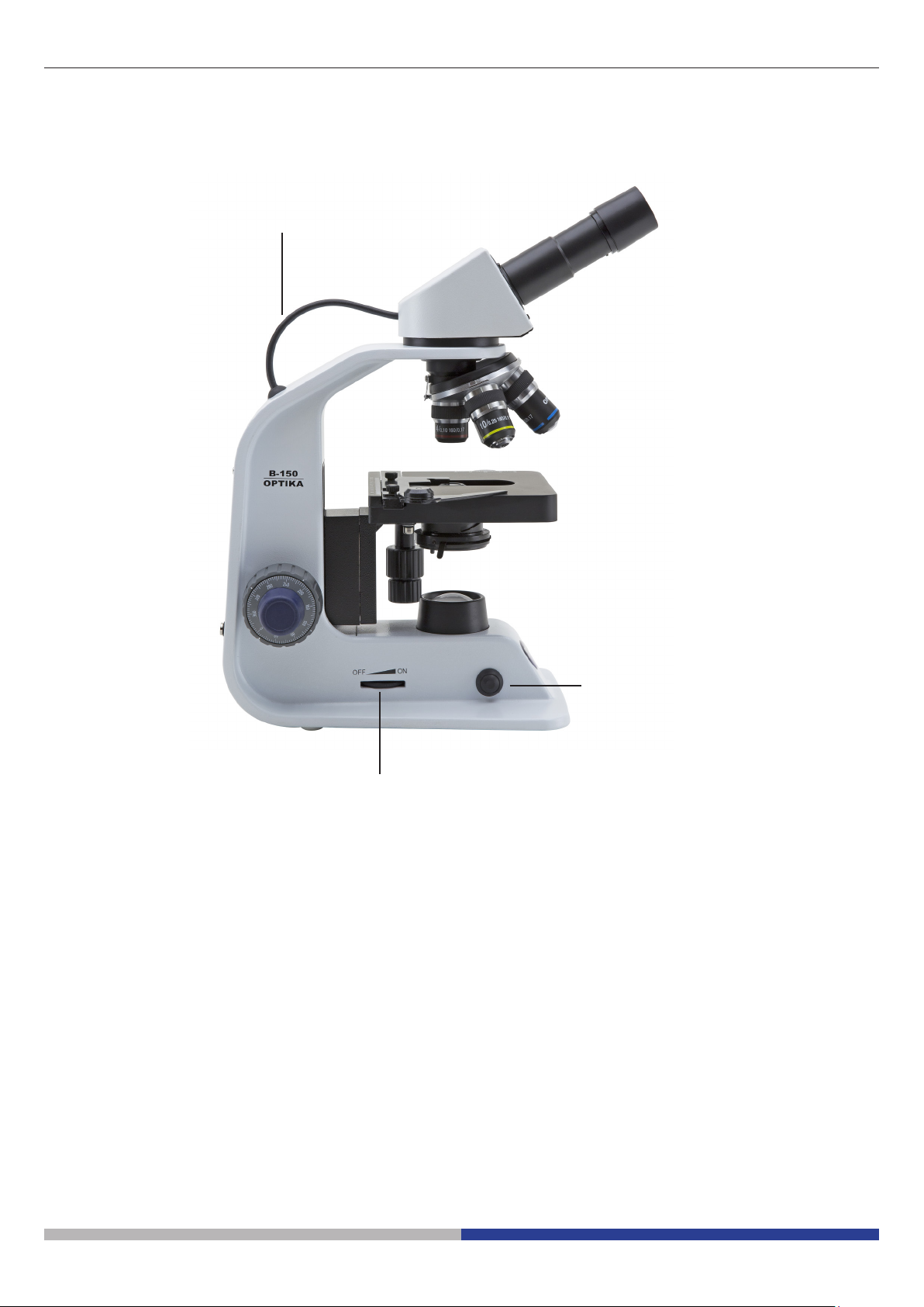
MAIN SWITCH / INTENSITY
ADJUSTMENT DIAL
ALC ON/OFF BUTTON
ALC CONNECTION CABLE
7.3 B-151ALC / B-153ALC / B-155ALC / B-157ALC / B-159ALC
This manual suits for next models
18
Table of contents
Languages:
Other Optica Microscope manuals


Popular Microscope manuals by other brands


VWR
VWR VisiScope 384 Series instruction manual

Nikon
Nikon ECLIPSE E200 POL instructions

Leica
Leica DI C800 User's manual & installation instructions

ThermoFisher Scientific
ThermoFisher Scientific Continuµm manual

ThermoFisher Scientific
ThermoFisher Scientific Continuµm manual

Olympus
Olympus SZ61 instructions