Warranty Information
1 (One) Year Warranty
Opticis warrants this MVDF to be free from defects in workmanship and mater
ials, under normal use and service, for a period of
one (1) year from the date of purchase from Opticis or its authorized resellers.
If a product does not work as warranted during the applicable warranty period,
Opticis shall, at its option and expense, repair the defective product or part, d
eliver to customer an equivalent product or part to replace the defective
item or refund to customer the purchase price paid for the defective product.
All products that are replaced will become the property of Opticis.
Replacement products may be new or reconditioned.
Any replaced or repaired product or part has a ninety (90) day warranty or the
reminder of the initial warranty period, whichever is longer.
Opticis shall not be responsible for any software, firmware, information, or me
mory data of customer contained in, stored on, or integrated with any product
s returned to Opticis for repair under warranty or not.
Warranty Limitation and Exclusion
Opticis shall have no further obligation under the foregoing limited warranty if
the product has been damaged due to abuse, misuse, neglect, accident,
unusual physical or electrical stress, unauthorized modifications, tampering,
alterations, or service other than by Opticis or its authorized agents, causes
other than from ordinary use or failure to properly use the product in the
application for which said product is intended.
Dispose of Old Electrical & Electronic Equipment
(Applicable in the European Union and other European countries with separate systems)
This symbol on the product or on its packaging indicates that this
product shall not be treated as household waste. Instead it shall be
handed over to the applicable collection point for the recycling of
electrical and electronic equipment. By ensuring this product is
disposed of correctly, you will help prevent potential negative
consequences for the environment and human health, which could
otherwise be caused by inappropriate waste handling of this product.
The recycling of materials will help to conserve natural resources. For more detailed
information about recycling of this product, please contact your local city office, your
household waste disposal service or the shop where you purchased the product.
1-10 Warranty Information
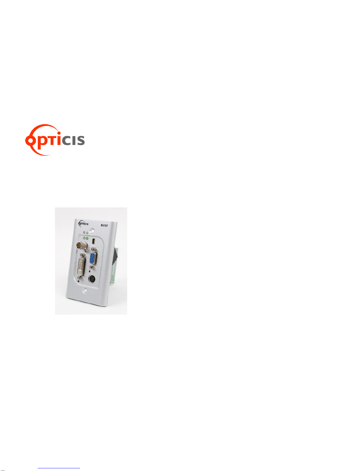
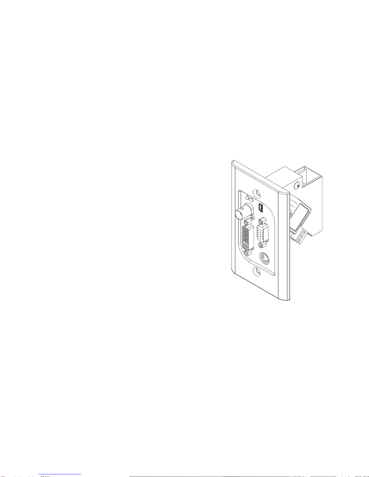
DVI, VGA, Composite and S-Video
1 x SC multi-mode fiber
SC terminated 1 core multi-mode fiber (50um)
Up to WUXGA (1920x1200) at 60Hz for DVI and VGA
input
Fixed resolution of SXGA (12080x1024) at 60Hz for
S-Video and Composite video input
Self-EDID for DVI and VGA
500m (1,640feet) @WUXGA, 60Hz
The MVDF provides auto source detection (First in, first
out) and video output priority when 4 video input signals
are connected at the same time. It gives priority at DVI,
VGA, S-Video and Composite video.
Power (Green), Video input status (Yellow)
US standard 1 gang size, PCB: 68 x 85mm
1-9 Technical Specification