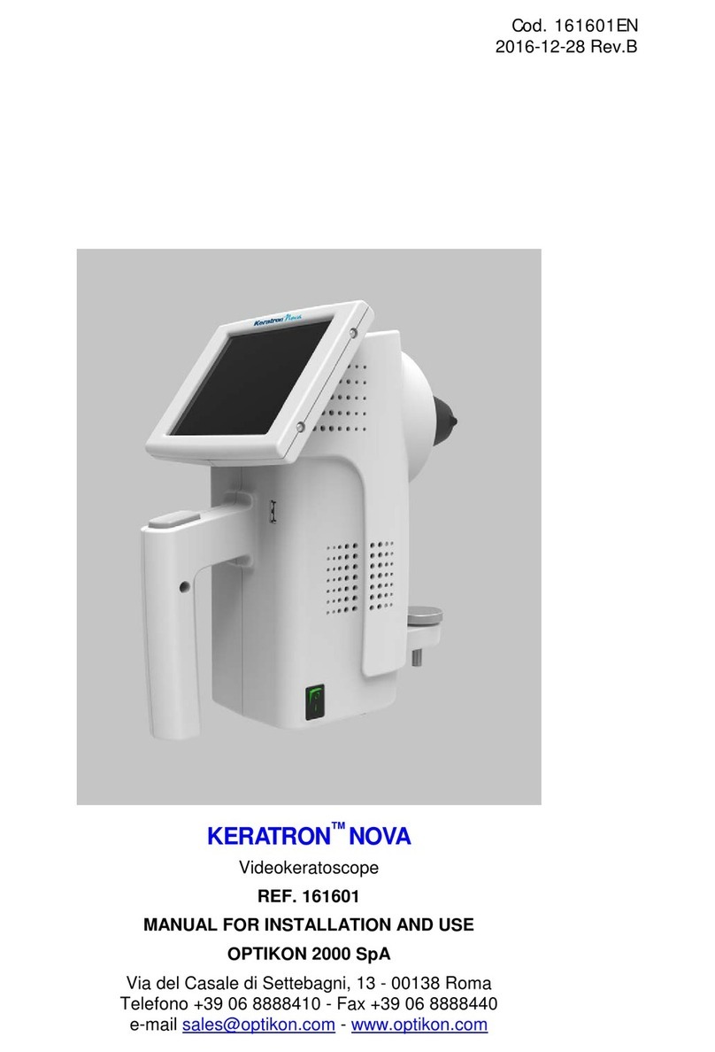
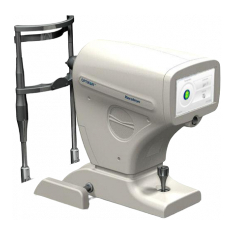
OPTIKON JANUS Reference manual

OPTIKON 2000 S.p.A. is an ISO 9001 and ISO 13485 certified company
that manufactures surgical and diagnostic ophthalmological instruments.
All OPTIKON 2000 products are manufactured in conformity with the
requirements of directive 93/42/CEE for medical instruments.

TABLE OF CONTENTS PAGE
1PRELIMINARY STATEMENT.......................................................................................................................1-1
2TERMS AND CONDITIONS OF LIMITED WARRANTY .........................................................................2-1
3WARNINGS.......................................................................................................................................................3-1
3.1 GENERAL WARNINGS...................................................................................................................................3-1
3.2 ENVIRONMENT WARNINGS ..........................................................................................................................3-1
3.3 ELECTRICAL WARNINGS ..............................................................................................................................3-2
3.4 GENERAL MAINTENANCE............................................................................................................................3-2
3.5 BIOMETRY SCAN..........................................................................................................................................3-3
3.6 PACHYMETRY SCAN ....................................................................................................................................3-3
3.7 FOOT PEDAL ................................................................................................................................................3-3
4SYMBOLS..........................................................................................................................................................4-1
5GENERAL INFORMATION ...........................................................................................................................5-1
5.1 SYSTEM DESCRIPTION..................................................................................................................................5-1
5.1.1 Biometry scan ........................................................................................................................................5-3
5.1.2 Pachymetry scans ..................................................................................................................................5-3
5.2 SPECIFICATIONS ..........................................................................................................................................5-4
5.2.1 Environmental specifications.................................................................................................................5-4
5.2.2 Electrical specification ..........................................................................................................................5-4
5.2.3 Technical specifications.........................................................................................................................5-5
5.2.4 Peripheral devices and connections ......................................................................................................5-7
5.2.5 Classification of the instrument in accordance with regulation EN 60601-1........................................5-7
5.2.6 Applied parts..........................................................................................................................................5-7
5.2.7 Foot pedal..............................................................................................................................................5-7
5.2.8 Dimensions of the instrument.................................................................................................................5-7
5.3 ELECTROMAGNETIC COMPATIBILITY CHARTS..............................................................................................5-8
5.3.1 Manufacturer’s guidebook and statement - Electromagnetic emissions................................................5-8
5.3.2 Manufacturer’s guidebook and statement – Electromagnetic immunity................................................5-9
5.3.3 Recommended separation distances between mobile and portable radiocommunication devices and
Janus 5-10
5.4 CIRCUIT DIAGRAMS...................................................................................................................................5-11
6INSTALLATION...............................................................................................................................................6-1
6.1 INTRODUCTION............................................................................................................................................6-1
6.2 OPENING THE PACKAGING AND INITIAL INSPECTION....................................................................................6-1
6.3 INSTALLATION PROCEDURE.........................................................................................................................6-2
6.4 SOUND SIGNALS ..........................................................................................................................................6-3
7SOFTWARE DESCRIPTION..........................................................................................................................7-1
7.1 MAIN MENU................................................................................................................................................7-1
7.2 PATIENT DATABASE.....................................................................................................................................7-2
7.3 TEST DATABASE ..........................................................................................................................................7-3
7.4 GENERAL SETTINGS.....................................................................................................................................7-4
7.5 INSTITUTION SETTINGS................................................................................................................................7-6
7.6 BIOMETRY...................................................................................................................................................7-7
7.7 IOL CALCULATION....................................................................................................................................7-10
7.8 PACHYMETRY............................................................................................................................................7-12
7.9 CALIBRATING THE PACHYMETER...............................................................................................................7-16
7.10 VERIFY FUNCTIONALITY ON THE PACHYMETRY TESTER ...........................................................................7-17

Janus Installation and Operation Manual
OPTIKON 2000
Code 141012EN 1-1 2015-07-14 Rev.B
1 PRELIMINARY STATEMENT
OPTIKON 2000 S.p.A requires that the user of this system should carefully read the
specific warnings detailed in this manual. It is the responsibility of the operator to ensure
that authorized personnel are fully acquainted with the correct functioning of the device
before using it. In no circumstances will OPTIKON 2000 S.p.A be responsible for any
lesions, or accidental or consequential damage caused to the purchaser, operators or
patients following use of the product.
Use of the system is subject to professional medical evaluation. OPTIKON 2000 S.p.A is
not liable for any clinical problems resulting from improper use of this product and will not
supply any medical advice.
OPTIKON 2000 S.p.A. will be liable for the safety, reliability and performance of the
device only if:
•updates, calibrations and repairs have been carried out by personnel authorised
by OPTIKON 2000 S.p.A.
•the system is used in conformity with the instructions for use;
•the electrical installation to which it is connected proves to conform to EN safety
regulations.
Every effort has been made to ensure that all illustrations and explanations in this
manual clearly describe the product and its operations at the time of being printed.
It is possible that, since this manual was printed, modifications may have been
made to satisfactorily meet the requirements of users. Occasionally, these
modifications can be made without prior notice.
OPTIKON 2000 S.p.A.
Via del Casale di Settebagni, 13
00138 Rome - Italy
Tel. +39 06 8888355
Fax. +39 06 8888440
e-mail sales@optikon.com
www.optikon.com
NOTE
The information in this manual is the property of OPTIKON 2000 S.p.A. Partial or
total reproduction of this information will be allowed only with the prior written
authorization of OPTIKON 2000 S.p.A.

Janus Installation and Operation Manual
OPTIKON 2000
Code 141012EN 2-1 2015-07-14 Rev.B
2 TERMS AND CONDITIONS OF LIMITED WARRANTY
All OPTIKON 2000 S.p.A instruments and accessories sold and installed in the European
Union are guaranteed for one year after date of invoice against manufacturing defects
and faulty materials. Warranty on consumer materials is limited to the first time the device
is used.
For terms and conditions applicable outside the European Union, please consult your
authorized OPTIKON 2000 S.p.A. distributor.
All components covered by warranty will be repaired or replaced free of charge.
The warranty includes an investigation into the cause of the defect, repair of the fault and
a final inspection of the unit and/or component/s.
The present warranty does not cover the consequences of improper use, accidents,
unprofessional use, manhandling or alterations carried out by anyone who is not an
OPTIKON S.p.A. authorised service technician.
In the event of any faults, OPTIKON S.p.A. reserves the right to verify whether the device
and/or its accessories have been altered or in any way manhandled, or damaged by
improper use.
In addition, OPTIKON S.p.A. reserves the right to modify the device and/or its
accessories should technical operations require it.
No warranty will be acknowledged if the serial number of the instrument and/or its
accessories assigned by OPTIKON 2000 S.p.A. should prove to be missing, manhandled
and/or not clearly legible.
The warranty does not cover the costs of the returning the instrument and the
accessories: all transport costs, packaging etc. are to be borne by the purchaser.
Should a specific request be made for the assistance of OPTIKON technicians, all
expenses for travel, board and lodging will be charged to the client.
OPTIKON 2000 S.p.A. `cannot be considered liable for damage caused during transport.
In this event, the client should notify the carrier responsible for delivery of the damage.

Janus Installation and Operation Manual
OPTIKON 2000
Code 141012EN 3-1 2015-07-14 Rev.B
3 WARNINGS
The following warnings will help the user to install the Janus ultrasound device correctly
and to use it safely and without any problems.
3.1 General warnings
All medical staff assigned to use the device should read and understand the instructions
detailed in this manual before using it. If your device does not work in the way described
in this manual, do not attempt to use it.
The use of this system is, however, a matter of professional medical judgement.
OPTIKON 2000 S.p.A. cannot be considered liable for any problems of a medical nature
resulting from improper use of this device, nor does it provide any advice of a medical
nature.
Should there be any traces on the monitor that are clearly not referable to an
ultrasound scan do not perform any kind of analysis or diagnosis; you should
contact the technical service department of Optikon 2000.
Do not modify this device without the manufacturer’s authorization.
3.2 Environment warnings
Do not install the device near sources of heat , and do not expose it to direct sunlight or
other sources of high temperatures.
Never use the system in the presence of inflammable anaesthetics, inflammable
disinfectants, or other substances that may cause fire of explosions.
Avoid using inflammable (N2O), (O2) anaesthetics , unless the gases have been
evacuated using a suitable system for gas aspiration.
Do not dispose of the Janus unit as undifferentiated urban refuse. It should be disposed
of separately in accordance with local laws and regulations relating to disposal of
electrical and electronic appliances .
Use of accessories and cables other than those supplied with the unit could cause
increased emissions or reduced system immunity. Emissions from portable
telecommunications devices can affect the performance of the unit.
These instructions for the installation and use of the unit must be followed scrupulously in
order to avoid dangerous interference with other devices positioned nearby. If the device
causes dangerous interference with other devices (verify this by switching the device on
and off), the user is advised to rectify the interference in one of the following ways:
-Reposition the other devices.
-Increase the distance between the instruments.
-Connect the unit to a different power point to which the other instruments are
connected.
-Consult the authorised dealer of the OPTIKON 2000 or an authorised service
technician.

Janus Installation and Operation Manual
OPTIKON 2000
Code 141012EN 3-2 2015-07-14 Rev.B
3.3 Electrical warnings
To avoid the risk of electric shock, do not remove the coverings of the instruments and its
accessories. Ensure that the maintenance and repair of the device is carried out by
technically qualified staff.
Connect the instrument to a power supply that conforms to the requirements detailed on
the rear panel of the device.
When the ultrasound instrument is not in use, disconnect it from the power supply.
Use Janus only with computers that meet the requirements of IEC60950 regulations.
If Janus unit is connected
•to a PC that has a class I power supply
or
•to a PC that has a class II (or battery-powered) power supply, to which devices
having class I power supply are connected
In case of damage of the protective conductor, the leakage current may exceed the value
specified by the standards for electrical medical devices.
In such conditions it is necessary, during installation, the use of an isolation transformer
which will be connected to the Janus unit, to your PC and to the peripherals connected to
it.
In the event of an emergency, or if the operator considers it urgently necessary to
disconnect Janus from the power supply, simply remove the power block from the
power supply.
During normal use, Janus should always be positioned so that it is easy to unplug
the power supply.
3.4 General Maintenance
Do not sterilize the probes using hot air or a chemical autoclave.
Do not use solvents or alcohol for cleansing the outside of the device .
The probes and their packaging are not sterile when supplied, and must be disinfected
before being used on patients.
The probes must be cleaned and sterilised between patients and between passings from
one eye to the other of the same patient.
If the correct measurement is in doubt, test the probe using the appropriate calibre
supplied with the device. Should the outcome be negative, or the functioning be irregular,
do not use the instrument and contact a service technician.

Janus Installation and Operation Manual
OPTIKON 2000
Code 141012EN 3-3 2015-07-14 Rev.B
3.5 Biometry scan
Apply the probe gently to the damp cornea and avoid altering its normal geometrical
configuration.
3.6 Pachymetry scan
Apply the probe gently to the patient’s cornea using the minimum pressure necessary to
keep the tip in contact.
3.7 Foot pedal
Do not lift or move the foot pedal by grabbing its cable.
Do not sterilize the foot pedal in the autoclave.
The foot pedal is not sufficiently waterproof to allow it to be used in the operating theatre.

Janus Installation and Operation Manual
OPTIKON 2000
Code 141012EN 4-1 2015-07-14 Rev.B
4 SYMBOLS
The following table details several IEC approved symbols, and their meanings. In the
absence of sufficient space, these symbols are often used on medical devices to allow
simple and speedy communication of information and warnings. Sometimes, one or more
symbols are combined to provide special meanings.
These are the symbols used on the Janus label. Before using the unit, users should
acquaint themselves with the symbols and their definitions shown in the table.
SYMBOLS PUBLISHED BY EN
SYMBOL DESCRIPTION SYMBOL DESCRIPTION
ALTERNATING CURRENT
CONSULT THE USER
MANUAL
DIRECT CURRENT
RECYCLING ELECTRICAL
AND ELECTRONIC
DEVICES
FOOT PEDAL
MANUFACTURER
APPLIED PART TYPE B
MANUFACTURE DATE

Janus Installation and Operation Manual
OPTIKON 2000
Code 141012EN 5-1 2015-07-14 Rev.B
5 GENERAL INFORMATION
The natural crystal piezoelectric effects observed for the first time by Pierre and Jacques
Curie in 1880. They demonstrated that certain types of crystal (quartzes, tourmaline),
when mechanically deformed, generate an internal electrical field. Conversely, when an
electrical field is applied to them a mechanical deformation of the crystals results. Some
ceramics, appropriately treated with a polarization procedure, acquire the piezoelectric
properties of the natural crystals. These ceramics, obtained using new technology, are
called piezoelectric. The biometry probe contains a piezoelectric ceramic which, when
stressed by an electrical impulse, vibrates at a frequency of 10 megahertz (10 million
oscillations per second). This movement of the ceramic probe generates an extremely
low ultrasound wave that crosses the cornea, aqueous humour, and the objects and
tissues found along the signal propagation path. The ultrasound wave partly passes
through the obstacles and is partly reflected by them towards the source (the probe). This
reflected energy takes a certain amount of time before returning to the probe, and this
time is proportional to the distance of the obstacle. Measuring this time, and the
experimental knowledge of the speed of the echo makes it possible to calculate
mathematically the distance of the object (the retina for example) from the emitter (the tip
of the probe). The properties of the echo sent back are processed by a fast
microprocessor which detects their reliability for making calculations (automatic
acquisition).
5.1 System description
The Janus ultrasound device – OPTIKON 2000 – is an instrument used for calculating the
axial length of the eye, for calculating the intraocular lens suitable for restoring
emmetropia after the removal of a cataract, and to measure corneal thickness.
Reliability, versatility, precision and ease, together with a pleasant and functional design
make it a unique device among those available on the world market. Its main functions
are activated by using a foot pedal, mouse, keyboard or touch-screen.

Janus Installation and Operation Manual
OPTIKON 2000
Code 141012EN 5-2 2015-07-14 Rev.B
Figure 1: Janus front panel: 1- Connector for external power block; 2-Foot pedal connector; 3-USB
connector; 4-LED signals indicating the device is on; 5-Probe connector.
1
2
3
4
5

Janus Installation and Operation Manual
OPTIKON 2000
Code 141012EN 5-3 2015-07-14 Rev.B
The main features of the ultrasound device are:
5.1.1 Biometry scan
•Precision
Differentiated measurements for pseudophakic eyes depending on the different materials
of the implants.
•Safety
Automatic criteria for accepting the measurements on the basis of the type of eye
examined (normal, pseudophakic, etc.).
•Measurements by immersion
Small bowl for carrying out accurate immersion scans.
•Latest generation formulas
Accurate measurements even with strongly ametropic eyes, or eyes that have been
subjected to refractive surgery.
5.1.2 Pachymetry scans
•Sensitivity
Corneal thickness up to 100µm automatically detected
•Versatility
Personalized corneal maps.
•Safety
Repeatable calculations for measurements with unsatisfactory standard deviations.

Janus Installation and Operation Manual
OPTIKON 2000
Code 141012EN 5-4 2015-07-14 Rev.B
5.2 Specifications
Manufacturer: OPTIKON 2000 S.p.A.
Via del Casale di Settebagni, 13
00138 Rome – Italy
Model: Janus Bio/Pachymeter
Regulatory Compliance: 93/42/CEE directive for medical devices
Technical standards: EN 60601-1
EN 60601-1-1
EN 60601-1-2
5.2.1 Environmental specifications
Storage: Temperature range: –10°C - +70°C
Humidity range: 10% - 100% (non-condensing)
In operation: Temperature range: +10°C - +35°C
Humidity range: 30% - 75%.
5.2.2 Electrical specification
Power supply: 12VS (external power block) o 5VS (USB)
Power consumption: 3.2W

Janus Installation and Operation Manual
OPTIKON 2000
Code 141012EN 5-5 2015-07-14 Rev.B
5.2.3 Technical specifications
General
Gain Variable up to 130dB
Sound signals Yes
Biometry scan
Probe: Piezoelectric with fixation light,
can be mounted on tonometry slide
Frequency: Approx. 10 MHz
Measurement depth: From 1 to 60 mm
Electrical resolution: Approx. 15 microns
Operating modes: Phakic, cataract, aphakic,
pseudophakic, manual
Lens type: PMMA, acrylic, silicone, “user def.”
Speed: Pre-set for each segment or modifiable by the user
Other settings: Eye with silicone oil
Measurements Average of 15 measurements and standard deviation
Measurement modes: Automatic and manual.
Calculation Formulas: SRKII, Haigis, Holladay, Hoffer Q, SRK/T, Post-
Refractive (Camellin-Calossi)

Janus Installation and Operation Manual
OPTIKON 2000
Code 141012EN 5-6 2015-07-14 Rev.B
Pachymetry scan
Probe: piezoelectric
Frequency approx. 50MHz
Measurement depth: from 100 to 1000µm in automatic mode
Resolution: approx. 0.5µm
Clinical accuracy : ±5µm
Available maps: 5 predefined + 5 customizable
Number of points per map: up to 49
Operating modes: automatic and manual
Calculation Formulas: ΔIOP tonometry measurement
Minimum PC Requirements
CPU: Intel Atom Dual Core N2800 1,65GHz
RAM: 1GB DDR3
HD: 320Gb
Display: 10.1"WSVGA 1024x600
USB ports: 1 x USB 2.0
Operating system: Windows XP

Janus Installation and Operation Manual
OPTIKON 2000
Code 141012EN 5-7 2015-07-14 Rev.B
5.2.4 Peripheral devices and connections
The Janus system is based on a 32 bit PC with Windows Operating System, and can
therefore use all the peripherals that the PC to which it is connected can support: printers,
modems, video projectors, masterisers, video printers, backup units, local networks, etc.
5.2.5 Classification of the instrument in accordance with regulation EN
60601-1
•Type of protection against electric shock: Class I
•Type of protection against damaging ingress of water: IPX1
•Safety levels of the application in the presence of a mixture of inflammable
anaesthetics: not suitable
5.2.6 Applied parts
•Probe output
•Level of protection against electric shock: B
5.2.7 Foot pedal
•Weight: 0.212Kg
•Type of protection against damaging ingress of water: IPX2
5.2.8 Dimensions of the instrument
Height : 32mm
Width: 205mm
Depth: 120mm
Weight: 530g
NOTE:
1) Weight and dimensions are approximate.
2) Specifications are subject to variation without prior notice.

Janus Installation and Operation Manual
OPTIKON 2000
Code 141012EN 5-8 2015-07-14 Rev.B
5.3 Electromagnetic compatibility charts
5.3.1 Manufacturer’s guidebook and statement - Electromagnetic emissions
Janus has been designed to operate in an electromagnetic environment detailed below. It
is the responsibility of the client or Janus operator to ensure that it is used in such an
environment.
Emissions test
Conformity
Electromagnetic environemnt - guide
RF Emissions
CISPR 11 Group 1
Janus uses RF energy only for its
internal operation. Therefore, its RF
emissions are very low and probably
cause no interference with nearby
electronic devices.
RF emissions
CISPR 11
Class B
Janus is suitable for use in all
environments, excluding domestic,
and those directly connected to a low
voltage power supply for public
buildings designated for domestic
use.
Warning: This product/system is
created to be used exclusively by
health professionals. This
product/system can cause radio-
interference or may disturb the
functioning of products placed
nearby. It may be necessary to adopt
measures to mitigate these
disturbances, such as the re-
orientation and the repositioning of
Janus or shielding the location.
Harmonic emissions
EN 61000-3-2
Class B
Voltage
fluctuations/flicker
emissions
EN 61000-3-3
Compliant

Janus Installation and Operation Manual
OPTIKON 2000
Code 141012EN 5-9 2015-07-14 Rev.B
5.3.2 Manufacturer’s guidebook and statement – Electromagnetic immunity
The Janus unit is designed to operate in an electromagnetic environment described
below. The client or Janus operator is responsible for ensuring that it is used in such an
environment.
Immunity test
EN 60601 Test level
Compliance level
Electromagnetic environment - Guide
electrostatic
discharge (ESD)
EN 61000-4-2
±6 kV with contact
±8 kV air
±6 kV with contact
±8 kV air
Floors should be in wood, concrete, or
ceramic. If the floors are covered in
synthetic material, relative humidity should
be at least 30%.
EFT/Burst
EN 61000-4-4
±2 kV for power supply lines
±1 kV for input/output lines
±2 kV power supply lines
±1 kV for input/output lines
The quality of the mains voltage should be
typical of a commercial or hospital
environment.
Surge voltages
EN 61000-4-5
±1 kV differential mode
± 2kV common mode
±1 kV differential mode d
± 2kV common mode
The quality of the mains voltage should be
typical of a commercial or hospital
environment.
Voltage dips, brief
interruptions, and
voltage variations on
power input lines
EN 61000-4-11
<5% U
T
(>95% dip in U
T
) for
0.5 cycles
40% UT(60% dip in UT) for 5
cycles
70% UT(30% dip in UT) for
25 cycles
<5% UT(>95% dip in UT) for
5 secs.
<5% U
T
(>95% dip in U
T
) for
0.5 cycles
40% UT(60% dip in UT) for 5
cycles
70% UT(30% dip in UT) for
25 cycles
<5% UT(>95% dip in UT) for
5 secs.
The voltage quality should be typical of a
commercial or hospital environment. If the
Janus user requires continued use, even
during an interruption to the mains voltage
network, Janus should be powered by UPS
or batteries.
.
Magnetic field
frequency (50/60 Hz)
EN 61000-4-8
3 A/m
Not applicable
The device does not contain
components sensitive to
magnetic fields.
Magnetic field frequencies should have
levels typical of a commercial or hospital
environment.
Conducted RF
EN 61000-4-6
Radiated RF
EN 61000-4-3
3 Veff
Between 150 kHz and 80
MHz
3V/m
Between 80 MHz and 2.5
GHz
3 Veff
3V/m
Mobile and portable RF communications
devices should not be used in the vicinity
of any part of Janus, including cables, or
the recommended separating distance
calculated with the equation applicable to
the frequency of the transmitter.
Recommended separation distance:
d= 1.2 P
d= 1.2
P
d= 2.3
P
where Pis the maximum nominal power
output of the transmitter in Watt (W) in
accordance with the manufacturer of the
transmitter, and d is the recommended
separation distance in meters (m). The
field intensity of the RF transmitters,
determined by an electromagnetic site
survey, could be lower than the compliance
level in each frequency level.
Interference can occur in the vicinity of
devices marked by the following symbol:

Janus Installation and Operation Manual
OPTIKON 2000
Code 141012EN 5-10 2015-07-14 Rev.B
NOTE:
UTis the a.c. mains voltage before applying the test level.
Note 1: At 80 MHz and 800 MHz, the highest frequency level is applied.
Nota2:These guidelines may not be applicable on all occasions. Electromagnetic
propagation is affected by absorption and reflection from buildings, objects and people.
a. Field intensity for fixed transmitters such as base stations for radiotelephones (cell
phones and cordless phones) and terrestrial mobiles, amateur radio equipment, AM
and FM radio transmitters and TV transmitters cannot theoretically or with accuracy
be predicted. To evaluate an electromagnetic environment caused by fixed RF
transmitters, an electromagnetic survey of the site should be considered. If the field
intensity calculated on the site where Janus is used exceeds the compliance levels
applicable (see above), the functioning of Janus should be placed under
observation. If abnormal performance is observed, other measures may be
necessary, for example a different orientation or position of the Janus device.
b. The field intensity in the frequency interval between 150 kHz and 80 MHz should be
lower than 3V/m.
5.3.3 Recommended separation distances between mobile and portable
radiocommunication devices and Janus
Janus is designed to operate in an electromagnetic environment in which RF radiated RF
noises are controlled. The client or operator of Janus can contribute to avoiding
electromagnetic interference by ensuring that the minimum distance between mobile and
portable RF communication devices (transmitters) and Janus as recommended below
with regard to the maximum output power of radio-communication devices are observed.
Maximum power
output of specified
transmitter (W)
Transmitter frequency separation distance (m)
between 150 kHz
and 80 MHz
d= 1.2 P
between 80 MHz and
800 MHz
d= 1.2 P
between 800 MHz and
2.5 GHz
d= 2.3 P
0.01
0.12
0.12
0.23
0.1
0.38
0.38
0.73
1
1.2
1.2
2.3
10
3.8
3.8
7.3
100
12
12
23
For transmitters specified for a maximum output power not detailed above, the
recommended separation distance din metres (m) can be calculated using the equation
applicable to the frequency of the transmitter where P is the maximum nominal output
power of the transmitter in Watt (W), in accordance with the manufacturer of the
transmitter.

Janus Installation and Operation Manual
OPTIKON 2000
Code 141012EN 5-11 2015-07-14 Rev.B
5.4 Circuit diagrams
On request, OPTIKON 2000 S.p.A. will make available circuit diagrams, a list of
components, descriptions, instructions for calibration or other information of assistance to
qualified technical personnel authorized to set-up or repair the instrument.
Table of contents
Other OPTIKON Measuring Instrument manuals
Popular Measuring Instrument manuals by other brands

Textron
Textron GREENLEE CJS-100 instruction manual

Kustom Signals
Kustom Signals ProLaser 4 quick start guide

FLIR
FLIR Extech Instruments MA410 manual

KROHNE
KROHNE OPTIFLUX 5000 Handbook

JEAN MÜLLER
JEAN MÜLLER PLNovameter 2000 Users’s Manual and Instructions for Installation

PKP
PKP DG03 instruction manual