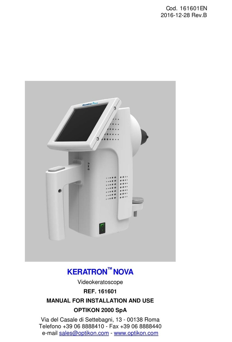
OPTIKON KERATRON User manual

Cod. 161501EN
2014-08-01 Rev.0
KERATRON™
Videokeratoscope Aberrometer
REF. 161501
INSTALLATION AND OPERATING MANUAL
OPTIKON 2000 S.p.A.
Via del Casale di Settebagni, 13 - 00138 Rome
Phone +39 06 8888410 - Fax +39 06 8888440
E-mail sales@optikon.com - www.optikon.com

Optikon 2000 SpA is an ISO 9001 and ISO 13485 certified company
which manufactures surgical and diagnostic devices for ophthalmology.
Its products are manufactured to satisfy the requirements of 93/42/EEC
Medical Devices Directive.

TABLE OF CONTENTS
.......................................................................... Page
1DISCLAIMER .............................................................. 1-1
2LIMITED WARRANTY CONDITIONS .................................... 2-1
3WARNINGS ............................................................... 3-1
3.1 GENERAL WARNINGS .............................................................. 3-1
3.2 ENVIRONMENTAL WARNINGS..................................................... 3-2
3.3 ELECTRICAL WARNINGS........................................................... 3-3
3.4 MECHANICAL WARNINGS ......................................................... 3-4
4SYMBOLS ................................................................. 4-1
5GENERAL INFORMATION ............................................... 5-1
5.1 SYSTEM DESCRIPTION ............................................................. 5-1
5.1.1 Topography in the Keratron .................................................. 5-2
5.1.2 The retro-mira, The bivalente mire cone and the Topography ......... 5-2
5.1.3 Main characteristics............................................................ 5-4
5.2 TECHNICAL SPECIFICATIONS ..................................................... 5-5
5.3 ELECTROMAGNETIC COMPATIBILITY TABLES .................................. 5-7
5.4 LIGHT EMISSION ..................................................................5-11
5.5 CIRCUIT DIAGRAMS ...............................................................5-11
5.6 COMPOSITION .....................................................................5-12
5.7 SOFTWARE DESIGNER ............................................................5-12
5.8 NOT SUPPLIED ACCESSORIES....................................................5-13
6INSTALLATION........................................................... 6-1
6.1 INTRODUCTION .................................................................... 6-1
6.2 UNPACKING AND INSPECTION.................................................... 6-1
6.3 INSTALLATION PROCEDURE ...................................................... 6-2
7USING THE KERATRON™ Home Screen............................... 7-1
7.1 TOPOGRAPHY CALIBRATION [CALIBRATION]................................... 7-2
7.2 SETTINGS ........................................................................... 7-6
7.3 CORNEAL TOPOGRAPHY [TOPOGRAPHY]....................................... 7-9
8TROUBLESHOOTING GUIDE ............................................ 8-1
8.1 TROUBLESHOOTING ............................................................... 8-1
9SOFTWARE KERATRON™ SCOUT ON THE EXTERNAL PC ........... 9-1
9.1 INTRODUCTION .................................................................... 9-1
9.2 DOWNLOAD THE KERATRON™ SCOUT FROM THE WEB........................ 9-2
9.3 KERATRON™ SCOUT SOFTWARE INSTALLATION ............................... 9-2
9.4 CONFIGURING THE DIRECT ETHERNET CONNECTIONTO THE EXTERNAL PC 9-
3
9.5 CONFIGURATION OF THE CONNECTION TO THE EXTERNAL PC USING A
LOCAL NETWORK........................................................................... 9-9

9.6 KERATRON™ SCOUT SOFTWARE STRUCTURE .................................9-13
9.7 CUSTOMIZING THE KERATRON™ SCOUT SOFTWARE .........................9-14
9.8 IDENTIFICATION OF THE SCOUT SOFTWARE VERSION .......................9-14
9.9 UNINSTALL KERATRON™ SCOUT SOFTWARE ..................................9-15
9.10 DESCRIPTION OF THE COMMANDS AND SCREENS OF THE KERATRON™ SCOUT
SOFTWARE .................................................................................9-16
9.10.1 INTRODUCTION.................................................................9-16
9.10.2 TRANSFERRING AN IMAGE FROM KERATRON™ .............................9-16
9.10.3 How to process, print and save images ....................................9-16
9.11 TROUBLESHOOTING KERATRON™ SCOUT SOFTWARE ........................9-17
9.11.1 KERATRON™ SCOUT SOFTWARE INSTALLATION............................9-17
9.11.2 THE FILE SCOUT.INI ...........................................................9-18
9.11.3 SHARING THE KERATRON™ SCOUT AMONG SEVERAL OPERATORS.......9-18
9.11.4 CHANGING THE PC ............................................................9-18
9.11.5 MISCELLANEOUS PROBLEMS ..................................................9-20
9.12 UPDATING KERATRON.EXE ......................................................9-22
10 CLEANING, STERILIZATION AND MAINTENANCE ...................10-1
10.1 CLEANING AND DISINFECTION ..................................................10-1
10.1.1 FOREHEAD REST AND MIRES CONE ..........................................10-1
10.1.2 CLEANING THE ACCESSORIES THAT ARE NOT PROVIDED .................10-2
10.2 STERILIZATION....................................................................10-2
10.3 MAINTENANCE ....................................................................10-2
10.3.1 REPLACING THE FUSE .........................................................10-2
10.3.2 REPLACING THE BUFFER BATTERY ..........................................10-3
11 INDEX ....................................................................11-1
12 APPENDIX ...............................................................12-1

Keratron™ Installation and operating manual
OPTIKON 2000
Cod. 161501EN 1-1 2014-04-23 Rev.0
1 DISCLAIMER
OPTIKON 2000 S.p.A. requests the users of this system to carefully read the specific
instructions found in the present manual. It is responsibility of the user to provide its
personnel with a thorough understanding of the equipment operation before use. In
no event shall Optikon 2000 S.p.A. be liable for any injury, incidental or
consequential damages incurred by the purchaser, users or patients as a result of
operation of the product.
The use of this system is subject to professional medical evaluation. Optikon 2000
S.p.A. is not responsible for any clinical problem resulting from mishandling this
equipment and makes no medical recommendations.
Optikon 2000 S.p.A. declares to be liable for safety, reliability and performance only
if:
Upgrades, calibrations, repairs are carried out by OPTIKON 2000 S.P.A.
authorized personnel.
the system is used in accordance with its instructions for use
the mains electric installation to which the system is connected complies with the
IEC Safety Regulations
NOTE
Every effort has been made to have all the illustrations and information
accurately represent the product and its operation as it actually was at the time
this operation manual was printed. Changes in some items may be made
during the life of this manual, so that we may effectively continue to meet the
requirements of users. At times, such modifications are made without advance
notice.
OPTIKON 2000 S.p.A.
Via del Casale di Settebagni, 13
00138 Rome - Italy
Phone +39 06 8888410
Fax +39 06 8888440
E-mail sales@optikon.com
www.optikon.com
NOTE: Information contained in this manual is proprietary with Optikon 2000
S.p.A. reproduction of any part or whole may only be performed with written
permission from OPTIKON 2000 S.p.A.

Keratron™ Installation and operating manual
OPTIKON 2000
Cod. 161501EN 1-2 2014-04-23 Rev.0
THIS PAGE IS INTENTIONALLY BLANK

Keratron™ Installation and operating manual
OPTIKON 2000
Cod. 161501EN 2-1 2014-04-23 Rev.0
2 LIMITED WARRANTY CONDITIONS
All OPTIKON 2000 S.P.A. equipment and accessories sold and installed in the
European Union are guaranteed against defective workmanship and faulty parts for
ONE YEAR, from the date of the invoice. The guarantee on the consumable material
is limited to the first use of the apparatus.
Please, inquire with your local Optikon Distributor for warranty conditions in countries
outside the European Union.
All items under warranty will be repaired or replaced free of charge.
Warranty includes the research of causes of the faults, reparation of the defect and a
final inspection of the unit, or part(s)..
This warranty does not cover any problems which are the result of improper use,
accidents, incorrect use and tampering or modifications made by persons who are
not part of the authorised OPTIKON S.p.A. technical service.
OPTIKON 2000 S.p.A. reserves the right to verify, in case of failures, if the
instrument and/or its accessories have been modified or tampered with in any way,
or if they have been damaged by improper use.
OPTIKON 2000 S.p.A. also reserves the right to modify the instrument and/or its
accessories in the event operating techniques require such modifications.
The warranty is not valid if the serial number of the instrument and/or accessories
attributed by OPTIKON 2000 S.p.A. is missing, tampered with and/or unreadable.
The warranty does not include the expenses for returning the instrument and
accessories: all charges for shipping, packaging etc. shall be borne by the buyer.
The device and its accessories must be returned in their original packaging. If they
are returned in a non compliant packaging, any damage arising from transportation
will not be covered by the warranty. If OPTIKON 2000 S.p.A. receives returned
products in packaging other the original one, it will return the products with the
appropriate packaging and charge the customer its costs.
In case of an expressly requested intervention of our technicians, all travel and hotel
expenses will be debited to the client.

Keratron™ Installation and operating manual
OPTIKON 2000
Cod. 161501EN 2-2 2014-04-23 Rev.0
THIS PAGE IS INTENTIONALLY BLANK

Keratron™ Installation and operating manual
OPTIKON 2000
Cod. 161501EN 3-1 2014-04-23 Rev.0
3 WARNINGS
3.1 GENERAL WARNINGS
For the correct use of the Keratron™ system, it is necessary to completely read
this manual. It must be used in compliance with the procedures and instructions
described herein.
Keratron™ must be connected to the power supply only as specified on the
power supply panel. Use exclusively the mains power cable provided or a cable that
is in compliance with safety regulations.
Do not connect to the system devices or accessories different from those
described in this manual.
The use of accessories or cables different from those provided with the unit
could cause an increase in emissions or a decrease in the immunity of the system.
The emissions originating from portable equipment for telecommunications could
affect the unit’s performance.
Carefully follow the instructions for the installation and use of the unit, so as to
prevent dangerous interference with other equipment located nearby. If this
instrument causes dangerous interference with other equipment ( this can be
caused by turning the unit on and off), it is recommended that the user attempt to
correct the interference with one or more of the following methods:
- Reorient or reposition the other instruments.
- Increase the distance between the instruments themselves.
- Connect the unit to a power outlet that is different from the one to which the other
instruments are connected.
- Consult the distributor or authorized Optikon 2000 S.p.A. Technical Service
Department.
Keratron™ has been developed and optimised to measure human eyes. The use
and the evaluation of Keraton ™Onda's in conditions that not comply with this
manual, or made by using surfaces having a reflectivity riflettività or a shape which is
far from those typical of human eyes (for example: contact lenses , surfaces having
discontinuity in the tangent or concavity in any of its section profiles, or surfaces
such to create multiple reflections or disappearance of some mire) cannot insure to
have the same degree of accuracy and thus it is strongly discouraged.

Keratron™ Installation and operating manual
OPTIKON 2000
Cod. 161501EN 3-2 2014-04-23 Rev.0
When used as a corneal topograph, situations that create mires jamming can
occur in human eyes in limited areas. This must be prevented by insuring a good
tearing and good image acquisitions (see in particular the chapters dedicated to the
eye acquisition and the last page of this manual), and eventually corrected by
properly using “Process Editing” functions. Therefore, you can either adjust mires
detection parameters or eventually discard artefacts . In any case, the user must
individually check that the mires reconstruction has been adequate before accepting
the topographic resulting data as valid.
The Keratron™ topographer does not perform diagnoses. . The operator should
not rely exclusively on parameters deriving from the instrument's measurement of the
curvature of the cornea, but use his/her own experience and qualifications to
correctly interpret the results.
In this manual the “.” (point) character has been adopted in place of the
“,”(comma) character as the decimal separator to maintain coherence with the
software messages and figures which use the Anglo-Saxon convention.
3.2 ENVIRONMENTAL WARNINGS
The environment in which the Keratron™ syste m is installed and used must
be in compliance with safety regulations.
Do not install the instrument near sources of heat or expose it to direct
sunlight or high temperatures.
The system must never be used in the presence of inflammable anesthetics,
inflammable disinfectants, or other substances which may cause fires or
explosions.
The use of flammable anaesthetics (N2O), (O2) should be avoided unless
they are removed by a gas aspiration system.
The device contains a lithium battery. The used batteries must be disposed
of in an adequate manner.
Do not dispose of Keratron™ as unsorted municipal waste. Collect it
separately according to the local laws/regulations on disposal of waste
electrical and electronic equipment ..

Keratron™ Installation and operating manual
OPTIKON 2000
Cod. 161501EN 3-3 2014-04-23 Rev.0
3.3 ELECTRICAL WARNINGS
The Keratron™ system functions in conjunction with a PC and relative
peripherals. The PC system (including the monitor and any additional
peripherals) to be connected to the device must be in compliance with
Standard EN 60601-1
f the device in question is connected to an apparatus whose compliance with
Standard EN 60601-1 is uncertain, the following are the risks:
Under normal operating conditions the risk of an excessive DISPERSION CURRENT
of the entire system towards the ground due to the dispersion current from
the non compliant device;
in the case of a single breakdown (interruption of the common protective
ground), the risk of an excessive dispersion current in the covering
resulting from the dispersion current from the noncompliant device
To avoid these risks, with a PC not compliant with EN 60601-1, we advise using
an isolation transformer placed between the PC (including the monitor and any
additional peripherals) and the wall power plug.
The PC, with its respective devices, must be positioned outside the patient area (at
least 1 metre away). Only the Keraton™ topographer can be positioned inside the
patient area.
Do not use mobile multiple power outlets for extension cords to power the
unit.
In case of use in the operating room, if several units are connected to the
patient or if these units are interconnected, have qualified personnel evaluate
any risks with regard to dispersion currents or system connections made
according to EN 60601-1 and EN 60601-1-1.
The operator should never touch at the same time the patient and parts
outside the patient area.

Keratron™ Installation and operating manual
OPTIKON 2000
Cod. 161501EN 3-4 2014-04-23 Rev.0
3.4 MECHANICAL WARNINGS
Be careful not to hit the patient with the cone, during measurements, when
moving the Keratron™ forward.
Do not touch any of the optical surfaces. Cleaning or maintenance is to be
performed by personnel authorized by Optikon 2000 S.p.A.

Keratron™ Installation and operating manual
OPTIKON 2000
Cod. 161501EN 4-1 2014-04-23 Rev.0
4 SYMBOLS
The table below shows some I.E.C. approved symbols and their meanings. In the
absence of sufficient space, these symbols are often used on medical instruments to
enable quick and simple communication of information and warnings. At times two or
more symbols are combined together in order to obtain special meanings.
These are the symbols used on the Keratron™. Before beginning to use the units,
familiarize yourself with the symbols and the definitions shown in the table.
SYMBOLS PUBLISHED BY IEC
SYMBOL
DESCRIPTION
ALTERNATING CURRENT
PROTECTIVE EARTH
ATTENTION!
OFF (POWER DISCONNECTION FROM THE MAINS)
ON (POWER DISCONNECTION FROM THE MAINS)
TYPE B
PART APPLIED TO THE PATIENT (BODY)
SEPARATED WASTE COLLECTION FOR
ELECTRICAL/ELECTRONIC EQUIPMENT
MANUFACTURER AND MANUFACTURING DATE

Keratron™ Installation and operating manual
OPTIKON 2000
Cod. 161501EN 4-2 2014-04-23 Rev.0
THIS PAGE IS INTENTIONALLY BLANK

Keratron™ Installation and operating manual
OPTIKON 2000
Cod. 161501EN 5-1 2014-04-23 Rev.0
5 GENERAL INFORMATION
5.1 SYSTEM DESCRIPTION
Figure 5-1: Keratron ™
The Keratron™ system is a topograph designed to provide information on the
cornea by representing it using the chromatic maps that are typical of corneal
topography (axial powers, curvatures, and corneal aberrometry) and to provide
information on the optical aberrations of the ocular or total wave front.
The main identifiable elements in the Keratron™ are shown in Figure 5-1. They are:
1. Power switch
2. 7” LCD display with touch-screen:
allows a live view of the patient’s eye for proper positioning of the
instrument during the measurement
allows the operator to send commands by using a special pen to touch virtual
cursors and buttons on the screen
Employs a user-friendly interface to notify the operator of the status of the unit
and any errors

Keratron™ Installation and operating manual
OPTIKON 2000
Cod. 161501EN 5-2 2014-04-23 Rev.0
3. Joystick with button: allows the cart to be moved in the X-Y-Z directions for
proper positioning of the optical head in relation to the patient and the start or
confirmation of the image acquisitions.
4. X-Y-Z cart
5. Optical head, with mires cone
6. Adjustable chin-rest with forehead-rest for positioning the patient during the
measurement.
5.1.1 TOPOGRAPHY IN THE KERATRON
The Keratron™is a corneal topographer (also called CAVK: Computer Assisted
VideoKeratographer) designed to measure the shape of the cornea and to represent
it as a chromatic map of the axial powers, of the local or Gaussian curvatures or of
the elevations in various formats.
From a "ray tracing" calculation on this shape the corneal aberrometry is calculated
and represented, i.e. the main component of the wave front and its aberrations, due
to the cornea-air interface.
5.1.2 THE RETRO-MIRA, THE BIVALENTE MIRE CONE AND THE
TOPOGRAPHY
The Keratron™mire cone has 26 alternate N/B and B/N edges, to which 2 from the
retro-mire are added (211 and 212 in Figure 5-2:) infra-red. In this way the mires
reflected on the Keratron cornea (Figure 5-2: bottom left) are the same as the other
Keratrons (28, at a uniform rate for the arc-step algorithm) without any compression
in the centre. This system, apart from allowing better tracing of the photopic pupil is
prepared for a possible "ugrading" of the Keratron topographer

Keratron™ Installation and operating manual
OPTIKON 2000
Cod. 161501EN 5-3 2014-04-23 Rev.0
Figure 5-2 : retro-mire working principle
To establish when the eye is at the ideal distance from the cone, the Keratron™
Onda uses an advanced version of the EPCS (Eye Position Control System)
electronic circuit adopted in the other topographs produced by Optikon 2000 S.p.A.
The eye's apex is intercepted by photocells when this is at a range around the
distance pre-set by the optical head. An indicator on the monitor and a sound alert
the operator when the eye is too near or far away, and permit capturing of the
images at the correct distance only.
The adoption of a double pair of photocells on the outside of the optical head in the
Keratron™, enables selection between the near distance, for the maximum
peripheral coverage, and that 3mm further away, to reduce invasiveness. These
choices can be made during the topographical acquisition by the touch-screen (e.g.
buttons 3 and 4 in Errore. L'origine riferimento non è stata trovata.).
The cone is backlit by a LED matrix with two wavelengths: the yellow-amber
(λ=590nm) to capture the topographical images and the infra-red (λ=940nm), the
same as the retro-mire, for the tracing of the pupil margin in scotopic conditions.
Behind this matrix is the fixture LED, focused a long distance away and a video
camera.
This video camera monitors and captures images of the eye in the two phases.
103
102
115
113
101
114
207
109
204
210
208
104
Topography
212
211

Keratron™ Installation and operating manual
OPTIKON 2000
Cod. 161501EN 5-4 2014-04-23 Rev.0
The operator thus can only take images, by pressing the pushbutton on the joystick
only when the patient eye is at a preset distance, which is the same distance at
which the instrument was formerly calibrated on a sphere having a known curvature
radius.
After the image has been acquired, specific algorithms reconstruct the shape of the
cornea by analyzing more than 7000 points located on the intersection between the
28 mires edges from black to white and from white to black and the 256 radials or
“meridians".
The curvature values are represented on the screen in the form of chromatic maps.
The centre of the rings represents the corneal apex, i.e. the point of the cornea
nearest to the video camera, as well as being an important reference point for all the
corneal maps. The entrance pupil is also detected in photopic conditions by the
removal of the clear rings in the image, and in scotopic conditions activating and
acquiring one or several images with the pupillometry in infra-red.
5.1.3 MAIN CHARACTERISTICS
The Keratron™videokeratoscope comprises of a central unit built around an
embedded PC. The commands are forwarded via a touch-screen integrated in a 7”
LCD display. The user interface is intuitive and the most immediately executed
commands, apart from via the touch-screen can be issued with the button on the
joystick.
For the processing and display and for the printing or filing of the examinations
communication will be made with a generic external PC (not included), on which the
Keratron "Scout" software is installed, via an Ethernet cable or via a wireless Wi-Fi
connection.

Keratron™ Installation and operating manual
OPTIKON 2000
Cod. 161501EN 5-5 2014-04-23 Rev.0
5.2 TECHNICAL SPECIFICATIONS
PARAMETER SPECIFICATIONS
Manufacturer: ............................. OPTIKON 2000 S.p.A.
Via del Casale di Settebagni, 13
00138 Rome - Italy
Model:......................................... Keratron™
Reference:.................................. 161501
Regulatory conformity: ............... Directive on medical devices 93/42/EEC
Technical standards: .................. EN 60601-1:1998; EN 60601-1-1:2000;
................................................... EN 60601-1-2:2001+A1:2006;
................................................... IEC 60825-1:1993+A1:1997+A2:2001;
................................................... EN 60601-1-4:1997+A1:1999
ENVIRONMENTAL SPECIFICATIONS
Storage:...................................... temp. range between -10°C and 60°C
................................................... humidity 0-100% (cond.included)
................................................... atm. pressure 500 to 1060 hPa
Operating:................................... temp. range between 10°C and +40°
................................................... humidity 30-75% (non condensing)
................................................... atm. pressure 700 to 1060 hPa
ELECTRICAL SPECIFICATIONS
KERATRON™
Input voltage:.............................. between 100 and 240 Volts AC
Frequency:.................................. 50/60 Hz.
Power consumption:................... 70 VA
Fuses:......................................... 2 x T 1 A ( 5 x 20 mm)
TOPOGRAPHY PRECISION

Keratron™ Installation and operating manual
OPTIKON 2000
Cod. 161501EN 5-6 2014-04-23 Rev.0
Simulated K-Readings:............... Within ± 0.25D on a normal cornea.
Distance error............................. BFS deviation: with Slit Lamp Adapter typical within
................................................... ±0.15D
Misalignement............................. Mean deviation on the map: ± 0.1 with misalignement
................................................... up to 1 mm °C.
LED wavelength.......................... 940nm e 590nm
PARAMETER SPECIFICATIONS
EQUIPMENT CLASSIFICATION ACCORDING TO IEC 60601-1
Type of protection against electric shock:............................ Class I
Degree of protection against electric shocks ....................... Type B
Degree of protection against ingress of water:..................... IPX0
Degree of safety of application in the presence of
a flammable anaesthetic mixture: ........................................ not protected
Mode of operation................................................................ continued
DIMENSIONS
Height:........................................ 440 mm
Width:......................................... 460 mm
Depth:......................................... 210 mm
Weight:....................................... app. 12 Kg
INTERFACE
LAN ............................................ Ethernet 10/100
USB............................................ 2.0
NOTES
The weight and dimensions indicated are approximate.
Specifications are subject to change without notice.
This manual suits for next models
1
Table of contents
Other OPTIKON Measuring Instrument manuals
Popular Measuring Instrument manuals by other brands

Turner
Turner AquaFlash user manual

Frient
Frient Electricity Meter Interface installation guide

OKTANTA
OKTANTA EM4000 user manual

EUTECH INSTRUMENTS
EUTECH INSTRUMENTS ECTest11 instruction manual

PCB Piezotronics
PCB Piezotronics 3743F11200G Installation and operating manual

Camille Bauer
Camille Bauer APLUS Safety instructions