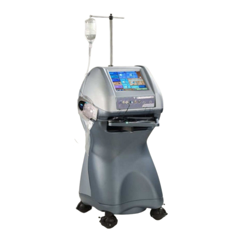
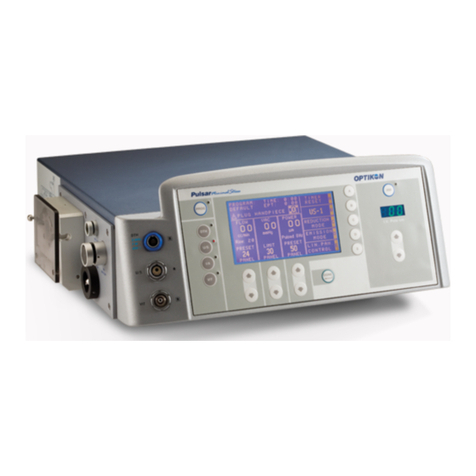
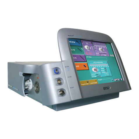
OPTIKON PULSAR 2 User manual

Cod. 111004S - Rev. D
PULSAR
2
SURGERY SYSTEM
SERVICE MANUAL
OPTIKON 2000 S.p.A.
Via del Casale di Settebagni, 13 - 00138 Rome Italy
Phone +39 06 8888355 - Fax. +39 06 8888440

Optikon 2000 SpA is an ISO 9001 and ISO 13485 certified
company which manufactures surgical and diagnostic devices for
ophthalmology.
Its products are manufactured to satisfy the requirements of
93/42/EEC Medical Devices Directive.

TABLE OF CONTENTS
1.
DISCLAIMER .................................................... 1-1
2.
TECHNICAL SPECIFICATIONS ................................ 2-1
2.1 DIATHERMY POWER CHARACTERISTICS.................................. 2-5
3.
WARNINGS ...................................................... 3-1
4.
GENERAL INFORMATION ..................................... 4-1
4.1 EQUIPMENT LAYOUT ....................................................... 4-1
4.1.1
FRONT VIEW (FIG.1) ................................................................... 4-1
4.1.2 LEFT SIDE VIEW (FIG. 2) ............................................................... 4-2
4.1.3
REAR PANEL (FIG. 3) ................................................................... 4-3
4.1.4
INTERNAL VIEW (FIG.4) ................................................................ 4-5
4.1.5
SIDE PLATE .............................................................................. 4-7
4.1.6
UNDER THE MONITOR .................................................................. 4-9
5.
PRINCIPLES OF OPERATION ................................. 5-1
5.1 INTRODUCTION ............................................................. 5-1
5.2 CONTROL BOARD 393200 .................................................. 5-6
5.3 GRAPHIC USER INTER ACE ................................................ 5-7
5.4 U/S DRIVER 347150 ....................................................... 5-14
5.4.1
SHEET 1 2 .............................................................................. 5-14
5.4.2
DIATHERMY DRIVER SECTION (SHEET 2 2) ........................................ 5-17
5.5 SENSORS BOARD 393120 .................................................. 5-22
5.6 VACUUM SIGNAL ILTER 369130 ........................................ 5-25
5.7 THE PULSAR
2
POWER BOARD 391110 ................................... 5-27
6.
CHECKS AND CALIBRATIONS ................................ 6-1
6.1 POWER SUPPLY BOARD 391110 ........................................... 6-1
6.2 CONTROL BOARD 393200 .................................................. 6-1
6.3 U/S DRIVER 347150 ........................................................ 6-1
6.4 THE SYSTEM CALIBRATION SO TWARE .................................. 6-2
6.4.1
CALIBRATION SOFTWARE INTERFACE DESCRIPTION ............................... 6-4
6.4.2
EXTERNAL PRESSURE SENSOR AND MAIN PRESS.REGULATOR CALIBRATION ... 6-5
6.4.3
SECONDARY PRESSURE REGULATOR CALIBRATION ................................ 6-6
6.4.4
PROPORTIONAL VALVE CALIBRATION ............................................... 6-6
6.4.5
VACUUM SENSOR CALIBRATION ...................................................... 6-7
6.4.6
TANK FULL ALARM CALIBRATION ..................................................... 6-7
6.4.7
PERISTALTIC PUMP FLOW CALIBRATION ............................................ 6-8
6.4.8
BUILDING THE LOOK UP TABLE ....................................................... 6-8
6.4.9
SYSTEM TESTS AND CALIBRATIONS .................................................. 6-8
6.5 TOUCH SCREEN CALIBRATION ........................................... 6-11
6.6 SETTING DATE AND TIME ................................................. 6-11
7.
TROUBLESHOOTING .......................................... 7-1
7.1 WARNING AND ERROR MESSAGES ........................................ 7-1
7.2 MAINS SUPPLY RELATED ERRORS ......................................... 7-5
8.
A AILABLE SPARE PARTS .................................... 8-1
THIS PAGE IS INTENTIONALLY BLANK

Pulsar
2
Service Manual
OPTIKON 2000
Cod. 111004SEN Rev.C
1-1
1. DISCLAIMER
OPTIKON 2000 S.p.A. requires the user of this system to carefully read specific
warnings found in this manual.
Optikon 2000 S.p.A. declares to be liable for safety, reliability and performance
only if:
•upgrades, calibrations, repairs are carried out by OPTIKON 2000 S.P.A.
authorized personnel
•the mains electric installation to which the system is connected complies
with the IEC Safety Regulations
IMPORTANT NOTICE
Every effort has been made to have all the illustrations and information
accurately represent the product and its operation as it actually was at the time
this operation manual was printed. Changes in some items may be made during
the life of this manual, so that we may effectively continue to meet the
requirements of users. On occasion, these changes may be made without
notice.
OPTIKON 2000 S.p.A.
Via del Casale di Settebagni, 13
00138 Rome Italy
Phone +39 06 8888355
Fax +39 06 88883440
e-mail [email protected]
www.optikon.com
NOTICE Information contained in this manual is proprietary with Optikon 2000
S.p.A. reproduction of any part or whole may only be performed with written
permission from OPTIKON 2000 S.p.A.

Pulsar
2
Service Manual
OPTIKON 2000
Cod. 111004SEN Rev.C
1-2
THIS PAGE IS INTENTIONALLY BLANK

Pulsar
2
Service Manual
OPTIKON 2000
Cod. 111004S 2007-06-20 Rev.B
2-1
2. TECHNICAL SPECIFICATIONS
PARAMETER SPECIFICATION
Manufacturer:....................... OPTIKON 2000 S.p.a.
via del Casale di Settebagni, 3
00 38 Rome - Italy
Model: ................................ PULSAR
2
Regulatory compliance: .......... 93/42/EEC Medical Devices Directive (MDD)
Technical standards: .............. EN 6060 - ; EN 6060 - - ; EN 6060 -
-2 ; EN 6060 -2-2
ENVIRONMENTAL SPECS
Storage: .............................. temp range – 0°C to +70°C, humidity 0- 00%
(non condensing)
Operation: ........................... temp range + 0°C to +40°C, humidity 30-75%.
ELECTRICAL SPECS
Input voltage: ....................... 00/ 20/220/230-240 V A.C. select.
Frequency: .......................... 50/60 Hz
Power consumption: ............... 50 W
Line fuses: ........................... 220/240 Volt: 2 A T
00/ 20 Volt: 4 A T
COMPRESSED AIR SPECS
Input air pressure: ................. from 500 to 800 KPa (72 to 6 PSI)
Air consumption: ................... 30 normal litre/minute
IRRIGATION
Fluid delivery: ...................... gravity fed - eye pressure determined by the
height of irrigation source
Valving element: ................... solenoid driven pinch valve
Control: .............................. system footswitch
ASPIRATION
Aspiration pump types: ............ Venturi and peristaltic
Actuating medium: ................. pressurized air from external source
pressure: 500÷800 KPa (72÷ 6 PSI)

Pulsar
2
Service Manual
OPTIKON 2000
Cod. 111004SEN Rev.C
2-2
PARAMETER SPECIFICATION
Flow: ................................. at least 30 normal litre/minute @ 500mmHg
Default vacuum level: ............. user programmable
Available vacuum range: .......... 5 to 500 mmHg
Default flow rate: .................. user programmable
Available flow rate range: ........ 2 to 50cc/min (peristaltic only)
Available aspiration rise time: ... three levels, slow, med, fast
Surgeon mode (linear aspiration): linear aspiration (vacuum and/or flow rate)
from 0 to preset linearly controlled via system
footswitch
Safety device: ...................... vacuum sensor; monitors the vacuum in the
aspiration line
Control: .............................. system footswitch
VIT (VITRECTOMY)
Handpiece type: .................... pneumatically powered guillotine cutter (VIT)
Cutting mode: ...................... reciprocating motion
Default cut rate: ................... user programmable
Available cutting rate: ............ from 60 to 2500 cuts per minute
Single cut: ........................... single cut mode available
Port size: ............................ adjustable from 0.2 to 0.7mm (reusable
cutters only)
Actuating medium: ................. pressurized air from external source
Operating pressure: ................ 200 KPa (29 +0/- .5 PSI)
Surgeon mode (Linear cut): ....... linear cut rate from 0 to preset controlled via
system footswitch
Control: .............................. system footswitch

Pulsar
2
Service Manual
OPTIKON 2000
Cod. 111004SEN Rev.C
2-3
PARAMETER SPECIFICATION
DIATH (DIATHERMY)
Type: ................................. bipolar generator - generator stops when RF
power is not needed
Operating frequency: .............. 2 MHz
Nominal power:..................... 7W (450 Ohm LOAD)
No load max. voltage: ............. 00 V
Default bipolar power: ............ user programmable
Available bipolar power: .......... 5 to 00% (percent).SURGEON MODE (linear
power): allows linear control of the
DIATHERMY power via system footswitch
depression
Handpiece type: .................... bipolar microforceps, slim stat pencil eraser,
intraocular diathermy pencils
Diathermy cable: ................... two poles, 26 gauges, 75 ohm, steam
autoclavable. Use only original OPTIKON 2000
S.P.A. diathermy cable
Control: .............................. system footswitch
PHACOEMULSIFIER
Handpiece type: .................... piezoelectric
Frequency: .......................... approx. 40KHz
Tip stroke: ........................... from 0 to 00µm
Power: ............................... panel or linear control of the U/S power via
system footswitch depression.
U/S Mode: ........................... Linear or Panel; Continuous, Short Pulse,
Single Burst, Multi-Burst, Continuous Burst
U/S Timer: .......................... from 0.00 minutes to 9.59 minutes – Equivalent
Phaco Time display

Pulsar
2
Service Manual
OPTIKON 2000
Cod. 111004SEN Rev.C
2-4
EQUIPMENT CLASSIFICATION ACCORDING TO
IEC 60601-1
Type of protection against
electric shock: ...................... class I
Degree of protection against electric shock:
Diathermy: .......................... Type BF, floating both at high and low
frequencies
U/S: .................................. Type B
Degree of protection against
harmful ingress of water (unit) : . IPX
Degree of protection against
harmful ingress of water
(footswitch): ........................ IPX8
Degree of safety of application
in the presence of a flammable
anaesthetic mixture: .............. not suitable
DIMENSIONS
Height: .................................. 33 cm
Width: ................................... 41 cm
Depth: ................................... 50 cm
Weight: .................................. 15 Kg
NOTE:
1) Weight and dimensions shown are approximate.
2) Specifications are subject to change without notice.

Pulsar
2
Service Manual
OPTIKON 2000
Cod. 111004S 2007-06-20 Rev.B
2-5
2.1 DIATHERMY POWER CHARACTERISTICS
ANTARES
DIATHERMY POWER vs LOAD
0
1
2
3
4
5
6
7
50 100 150 200 250 300 350 400 450 500 550 600 650 700 750
W
a
t
t
Ohm
Preset=100% Preset=50%
Diathermy Power vs load
ANTARES
DIATHERMY POWER vs PRESET
0
1
2
3
4
5
6
7
10 20 30 40 50 60 70 80 90 100
W
a
t
t
Percent
Load=450 Ohm
Diathermy Power vs Preset
PULSAR
2
PULSAR
2

Pulsar
2
Service Manual
OPTIKON 2000
Cod. 111004SEN Rev.C
2-6
THIS PAGE IS INTENTIONALLY BLANK

Pulsar
2
Service Manual
OPTIKON 2000
Cod. 111004S 2007-06-20 Rev.B
3-1
3. WARNINGS
NOTE: THIS INFORMATION IS BELIEVED TO BE CURRENT AT THE TIME
OF PUBLICATION, BUT IS PROVIDED WITHOUT WARRANTY OF ANY KIND
AND WE ASSUME NO RESPONSIBILITY WITH RESPECT THERETO.
) SERVICE AND REPAIR OF THE SYSTEM SHOULD BE RESTRICTED QUALIFIED
TECHNICAL PERSONNEL AUTHORIZED BY OPTIKON 2000.
2) THE "OPTIKON PULSAR
2
" CONTROL CONSOLE IS PROVIDED WITH A VOLTAGE
CHANGER. CHECK THAT THE CONSOLE IS SET TO THE PROPER VOLTAGE
BEFORE CONNECTING TO A MAINS SUPPLY. TO GUARANTEE SAFETY, A
HOSPITAL GRADE POWER CORD AND PLUG MUST BE USED, THE UNIT MUST BE
GROUNDED.
NOTE: SETTING A DIFFERENT INPUT VOLTAGE MAY REQUIRE REPLACING
THE MAINS FUSES. REFER TO THE TECHNICAL SPECIFICATIONS PARAGRAPH.
3) THE SYSTEM SHOULD NEVER BE USED IN THE PRESENCE OF FLAMMABLE
ANAESTHETICS, DISINFECTING AGENTS, CLEANING AGENTS, ETC., DUE TO
POSSIBLE FIRES OR EXPLOSION.
4) TO REDUCE THE RISK OF ELECTRIC SHOCK, UNPLUG THE EQUIPMENT FROM
THE MAINS BEFORE REMOVING COVER FOR SERVICING.
5) THE "PULSAR
2
" CONTROL CONSOLE SHOULD BE CONNECTED TO A MAINS
SUPPLY ONLY AS MARKED ON THE REAR PANEL. TO GUARANTEE SAFETY, A
HOSPITAL GRADE POWER CORD AND PLUG MUST BE USED, THE UNIT MUST BE
GROUNDED.
6) FOR OPERATING SAFETY DO NOT INSTALL THE SYSTEM IN A LOCATION WHERE
IT WILL BE EXPOSED TO HEATING EQUIPMENT OR RADIATORS, DIRECT
SUNLIGHT, OR ANY OTHER SOURCE OF EXTREMELY HIGH TEMPERATURES.
7) DO NOT INSTALL THE "PULSAR
2
" SYSTEM IN SUCH A WAY THAT THE
VENTILATING OPENINGS ARE BLOCKED.
8) BE SURE THAT THE POWER SWITCH ON THE CONTROL CONSOLE IS OFF WHEN
PLUGGING IN, OR REMOVING THE POWER CABLE FROM A WALL OUTLET.
9) TURN OFF THE MAIN POWER SWITCH WHENEVER THE PULSAR
2
UNIT IS NOT IN
USE.
0) RISK OF BURNS OR FIRE; DO NOT USE DIATHERMY NEAR CONDUCTIVE
MATERIALS SUCH AS METAL BED PARTS, INNER-SPRING MATTRESSES, AND THE
LIKE. RENEW ELECTRODE CABLES UPON EVIDENCE OF DETERIORATION.
) SEVERE RF BURNS CAN RESULT IF THE DIATHERMY OUTPUT CURRENT IS
DIVERTED TO THE OPERATOR BY CARELESS HANDLING.
2) WHEN THE BIPOLAR DIATHERMY HANDPIECE AND A MONITORING SYSTEM ARE
USED AT THE SAME TIME, ALL THE ELECTRODES OF THE MONITORING SYSTEM

Pulsar
2
Service Manual
OPTIKON 2000
Cod. 111004SEN Rev.C
3-2
THAT ARE NOT PROTECTED BY RESISTORS OR HIGH FREQUENCY INDUCTORS
SHOULD BE PLACED AS FAR AWAY AS POSSIBLE FROM THE DIATHERMY
ELECTRODES.
3) THE CABLE OF THE BIPOLAR DIATHERMY HANDPIECE SHOULD NOT TOUCH THE
PATIENT OR OTHER CABLES.
4) ALWAYS USE THE LOWEST OUTPUT DIATHERMY POWER LEVEL WHICH IS
COMPATIBLE TO THE SURGICAL APPLICATION.
5) AN EVIDENT LOW OUTPUT LEVEL OR A FAULTY OPERATION OF THE BIPOLAR
DIATHERMY HANDPIECE, EVEN THOUGH THE INSTRUMENT HAS BEEN SET FOR A
NORMAL USE, MAY INDICATE A BAD CONTACT IN THE ELECTRODES
CONNECTION.
6) DURING BIPOLAR DIATHERMY HANDPIECE OPERATION, DO NOT USE FLAMMABLE
ANAESTHETICS NITROGEN MONOXIDE, OXYGEN, UNLESS THEY ARE VENTED BY
A SUITABLE ASPIRATION SYSTEM.
7) FLAMMABLE MATERIALS SUCH AS DISINFECTING AGENTS AND CLEANING AGENTS
SHOULD BE EVAPORATED BEFORE USING THE BIPOLAR DIATHERMY HANDPIECE.
SOME MATERIALS SUCH AS COTTON WOOL OR GAUZE, IF SOAKED WITH
OXYGEN, CAN CATCH FIRE BECAUSE OF THE SPARKS CAUSED BY THE
INSTRUMENT IN ITS NORMAL USE.
8) THERE IS A POSSIBLE RISK FOR PATIENTS CARRING CARDIAC STIMULATOR OR
STIMULATING ELECTRODES BECAUSE OF RF INTERFERENCE CAUSED BY
DIATHERMY GENERATOR. THE STIMULATOR ITSELF CAN FAIL. SHOULD ANY
DOUBT ARISE, APPLY TO THE CARDIOLOGY DIVISION FOR ADVICE.
9) CAUTION: POSSIBLE INTERFERENCE WITH OTHER MEDICAL EQUIPMENT WHEN
THE BIPOLAR DIATHERMY HANDPIECE IS IN USE.
20) EXCHANGING FUSES SHOULD BE DONE A FEW MINUTES AFTER THE MAINS
SWITCH HAS BEEN TURNED OFF IN ORDER TO ALLOW TIME FOR COOLING.
2 ) REPLACE FUSE AS MARKED.
22) NEVER LIFT OR MOVE FOOTSWITCH BY THE CABLE. DAMAGE MAY RESULT.
23) DO NOT ALLOW THE TIP OF THE VITRECTOMY PROBE, DIATHERMY, OR I/A
HANDPIECE TO TOUCH METALLIC OBJECTS.
24) DO NOT ATTEMPT TO ALTER THE SHAPE OF ANY PART OF A HANDPIECE.
25) DO NOT ATTEMPT TO SEPARATE THE PLUG FROM THE CABLE.
26) DO NOT SUBJECT THE HANDPIECE TO HOT AIR STERILIZATION OR
"CHEMCLAVE".
27) DO NOT STORE OR USE THE HANDPIECE IF WET OR MOIST.
28) DO NOT ACTIVATE THE VITRECTOMY HANDPIECE WITH THE TIP IN AIR. THE TIP
SHOULD ALWAYS BE TEST RUN IN A BEAKER OF STERILE SOLUTION. TESTING IN
AIR WILL CAUSE IRREPARABLE DAMAGE TO THE TIP.

Pulsar
2
Service Manual
OPTIKON 2000
Cod. 111004SEN Rev.C
3-3
29) HANDPIECES AND OTHER NON DISPOSABLE ACCESSORIES ARE SUPPLIED NON
STERILE. THEY MUST BE FIRST CLEANED, THEN STERILIZED IN AUTOCLAVE AS
INDICATED ON THE RELATIVE INSTRUCTIONS. THEY COULD BE DAMAGED BY
THE USE OF OTHER STERILIZATION METHODS, LIKE HOT AIR OR "CHEMCLAVE"
STERILIZATION.
30) THE USE OF INFLAMMABLE ANAESTETICS, (N
2
0 ), ( 0
2
), SHOULD BE AVOIDED
UNLESS THEY ARE REMOVED BY A GAS ASPIRATION SYSTEM.
3 ) DO NOT ACTIVATE THE PHACO U/S HANDPIECE WITH THE PHACO TIP IN AIR.
THE ULTRASONIC POWER SHOULD BE APPLIED TO THE PHACO HANDPIECE WITH
THE PHACO TIP IMMERSED IN A TEST CHAMBER FILLED WITH INFUSION FLUID
OR IN A BEAKER OF STERILE FLUID AT AMBIENT TEMPERATURE. OTHERWISE
HANDPIECE DAMAGE MAY RESULT.
32) DO NOT CHECK VIBRATION BY PLACING HAND OR FINGER AGAINST HANDPIECE
TIP. PROLONGED EXPOSURE TO OR DIRECT CONTACT WITH THE VIBRATING TIP
MAY CAUSE DAMAGE TO HEALTHY TISSUE.
33) THE PHACO HANDPIECE MUST BE CONNECTED TO THE PULSAR
2
IRRIGATION-
ASPIRATION SYSTEM AND MUST NOT BE USED WITHOUT IT.
34) BEFORE USING A SURGICAL OR NON SURGICAL ACCESSORY IN CONNECTION
WITH PULSAR
2
, VERIFY THE COMPATIBILITY OF THE SAME WITH PULSAR
2
EQUIPMENT. COMPATIBILITY IS STATED ON THE ACCESSORY ACCOMPANYING
DOCUMENT.
35) DISPOSE WASTE COLLECTION FLUIDS ACCORDING TO THE LOCAL
LAWS/REGULATIONS ON DISPOSAL OF ORGANIC MATERIALS.
36) SOUND EMISSION CAPABILITY OF THE EQUIPMENT IS TESTED AT POWER-ON.
VERIFY THAT AN AUDIBLE BEEP IS EMITTED DURING SYSTEM BOOT.
37) A ROTATING LOGO, PLACED AT THE LOWER SIDE OF THE USER INTERFACE
SCREEN, SHOWS THAT THE SYSTEM IS RUNNING PROPERLY. IF SUCH SYMBOL
STOPS MOVING IT MEANS THAT THE SYSTEM IS IDLE AND EQUIPMENT
OPERATION MUST BE STOPPED.
38) THE “PC UPLINK” CONNECTION IS INTENDED FOR SERVICE PURPOSE ONLY. DO
NOT CONNECT ANY EXTERNAL DEVICE DURING SURGICAL USE OF THE
EQUIPMENT.

Pulsar
2
Service Manual
OPTIKON 2000
Cod. 111004SEN Rev.C
3-4
THIS PAGE IS INTENTIONALLY BLANK

Pulsar
2
Service Manual
OPTIKON 2000
Cod. 111004S 2007-06-20 Rev.B
4-1
4. GENERAL INFORMATION
4.1 EQUIPMENT LAYOUT
This section contains information on the equipment layout. All operating controls
and adjustments are identified and described further on. Sockets and other
elements on the front panel are described in Fig. Left side (pump side) of the
instrument is described in Figure 2. Rear panel connectors are identified in Figure
3.
4.1.1 FRONT VIEW (FIG.1)
1) LCD TOUCH-SCREEN DISPLAY
By means of this LCD touch-screen the user can
activate the proper functions
setup all parameters
read all actual and preset values
read warnings and error messages
program the equipment and footswitch
2) DIATHERMY SOCKET
Bipolar diathermy handpiece cable fits into this socket.
3) U/S (P aco) SOCKET
Phaco handpiece connector plugs into this socket.
4) VIT SOCKET
The activation line of the vitrectomy handpiece plugs into this socket.

Pulsar
2
Service Manual
OPTIKON 2000
Cod. 111004SEN Rev.C
4-2
4.1.2
LEFT SIDE VIEW (FIG. 2)
1) IRRIGATION PINCH VALVE
The irrigation line is run through this valve. The valve allows starting and
stopping irrigation at surgeon’s demand.
2) REFLUX PINCH VALVE
The Reflux/Venting pinch valve permits introduction of fresh BSS solution in the
aspiration line, thus releasing the vacuum in the line and, eventually, reversing
direction of flow.
3) ACS3 VACUUM SENSOR
The ACS3 vacuum sensor monitors the vacuum level in the aspiration line in a
sterile manner. It also prevents sudden vacuum surges, thus stabilizing the
anterior chamber.
4) PERISTALTIC PUMP
This pump allows peristaltic aspiration in the PULSAR 2. The pump rotor is
automatically moved vertically to allow tubing installation and/or Venturi
aspiration.
5) WASTE COLLECTION TANK SUPPORTS
These two brackets support and hold in place the waste collection rigid tank at
the end of the aspiration path.

Pulsar
2
Service Manual
OPTIKON 2000
Cod. 111004SEN Rev.C
4-3
4.1.3 REAR PANEL (FIG. 3)
1) COOLING FAN
Removes hot air from the unit.
2)
CONNECTOR FOR VIDEO OVERLAY
This connector makes it possible the connection to the "Eclipse" Video
Overlay device, which allows you to superimpose the main parameters
on the video shot during surgery.
3) GAS INLET
Compressed air supply at a pressure of 5-8bars (72.5- 6PSI) must be
connected to this input. This air is used by the PULSAR2 to operate Venturi
pumps, vitrectomy cutter, pneumatic micro-scissors and silicone injection.
4) GAS FILTER
This filter removes humidity and particles from the compressed air supplied to
the PULSAR2 unit. Depress the pin of the pin valve (Fig.3 No. ) at the lower
section of the filter to evacuate the water that condenses in the polycarbonate
container.
5) FILTER OUTLET
The filtered air leaves from this outlet. Connect the tube supplied with the
unit to the "AIR INPUT" (Fig.3 No. 0).
6) PC UPLINK
This is the PULSAR2-PC interface for data download/upload and software
upgrade.
7) REMOTE CONTROL
This is the remote control connector.

Pulsar
2
Service Manual
OPTIKON 2000
Cod. 111004SEN Rev.C
4-4
8) POWER
This is the A.C. voltage input of the module. The mains fuses are located in
this device. The mains voltage selector, on the fuse holder cover, is factory set
to the voltage available at your location.
9) FOOTSWITCH CONNECTOR
This is the system footswitch connector socket. Footswitch depression
activates the PULSAR2 functions.
10) AIR INPUT
Through this input compressed air is supplied to the unit. FILTER OUTLET
(Fig.3 No.5) must be connected to it.
11) EXHAUST PIN VALVE
This is the discharge valve for the humidity condensed in the gas filter. Gently
depress the valve to evacuate water from the filter polycarbonate container.
12) I.V. POLE CONNECTOR
This connector provides a direct interface to the OPTIKON AUTOMATIC I.V.
POLE.
13) POWER (ON/OFF MAINS SWITCH ASSEMBLY)
The power switch is used to switch on/off the unit. The Mains fuses and the
power cord socket are located close to this switch.
14) EXPANSION UNIT CONNECTOR
This connector controls an auxiliary OPTIKON 2000 S.P.A. equipment that
complements the PULSAR
2
by extending its range of use to the surgery of the
posterior segment of the eye.
15) AIR OUTPUT
This connector delivers air at a regulated pressure to the silicone injection
system of the VIT MODULE UNIT.
Table of contents
Other OPTIKON Medical Equipment manuals

OPTIKON
OPTIKON Keratron Piccolo User manual

OPTIKON
OPTIKON PULSAR MS User manual

OPTIKON
OPTIKON R-Evo Smart E Reference manual

OPTIKON
OPTIKON ASSISTANT User manual

OPTIKON
OPTIKON HiScan User manual

OPTIKON
OPTIKON BIOLINE User manual

OPTIKON
OPTIKON PULSAR2 ESP User manual

OPTIKON
OPTIKON KERATRON ONDA User manual

OPTIKON
OPTIKON 2000 User manual

OPTIKON
OPTIKON KERATRON SCOUT User manual