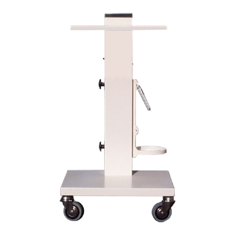
OPTIKON CRYO-LINE Reference manual

OPTIKON 2000 S.p.A. is an ISO 9001 and ISO 13485 certified company that
produces surgical and diagnostic devices for ophthalmology.
All OPTIKON 2000 products are manufactured in compliance with the
requirements of Directive 93/42/EEC on medical devices.

CONTENTS
1. DISCLAIMER........................................................................1-1
2. LIMITED WARRANTY CONDITIONS .............................................2-1
3. WARNINGS .........................................................................3-1
4. SYMBOLS ...........................................................................4-1
5. GENERAL INFORMATION.........................................................5-1
5.1 THEORY OF OPERATION.................................................................5-1
5.2 DESCRIPTION OF THE SYSTEM..........................................................5-1
5.3 TECHNICAL SPECIFICATIONS............................................................5-2
5.4 EMC TABLES ..............................................................................5-3
5.4.1 ELECTROMAGNETIC EMISSIONS........................................................................... 5-3
5.4.2 ELECTROMAGNETIC IMMUNITY ........................................................................... 5-4
5.4.3 RECOMMENDED SEPARATION DISTANCES ............................................................... 5-5
5.5 WIRING DIAGRAMS.......................................................................5-6
6. INSTALLATION AND MAINTENANCE............................................6-1
6.1 INTRODUCTION...........................................................................6-1
6.2OPENING THE PACKAGE AND INITIAL INSPECTION ..................................6-1
6.3 INSTALLATION PROCEDURE.............................................................6-1
7. OPERATION OF THE APPARATUS ..............................................7-1
7.1 DESCRIPTION OF THE APPARATUS.....................................................7-1
7.1.1 DISPLAY ...................................................................................................... 7-1
7.1.2 SYSTEM STATES............................................................................................. 7-1
7.1.3 INITIAL TEST OF THE SYSTEM ............................................................................ 7-1
7.1.4 STANDARD OPERATION .................................................................................... 7-1
7.1.5 TEMPERATURE CONTROL.................................................................................. 7-1
7.1.6 APPLICATION TIME CONTROL............................................................................. 7-2
7.1.7 APPLICATION TIME AND APPLIED TEMPERATURE CONTROL......................................... 7-2
7.2 CONFIGURATION OF THE UNIT.........................................................7-3
7.3 USER INTERFACE.........................................................................7-5
7.4 SOUND MESSAGES........................................................................7-6
8. USER INTERFACE..................................................................8-1
8.1 LANGUAGE SELECTION..................................................................8-1
8.2 STANDARD OPERATION..................................................................8-1
8.3 APPLICATION TIME CONTROL ..........................................................8-2
8.4 APPLICATION TEMPERATURE CONTROL...............................................8-3
8.5 SYSTEM TEST .............................................................................8-5
8.6 SHUTDOWN PROCEDURE................................................................8-6
9. CLEANING, STERILIZATION AND MAINTANENCE.............................9-1
9.1 CLEANING.................................................................................9-1
9.1.1 UNIT .......................................................................................................... 9-1
9.1.2 ACCESSORIES................................................................................................ 9-1
9.2 STERILIZATION ...........................................................................9-2
9.2.1 UNIT .......................................................................................................... 9-2
9.2.2 CRYOSURGICAL PROBES................................................................................... 9-2
9.3 MAINTENANCE............................................................................9-2
9.3.1 UNIT .......................................................................................................... 9-2
9.3.2 ACCESSORIES................................................................................................ 9-2
10. TROUBLESHOOTING GUIDE ................................................... 10-1
10.1 WARNINGS AND ERROR MESSAGES................................................... 10-1
10.2 MISCELLANEOUS PROBLEMS .......................................................... 10-2
11. ACCESSORIES ....................................................................11-1
11.1 RECOMMENDED ACCESSORIES ........................................................ 11-1
11.2 AVAILABLE CRYOSURGICAL PROBES................................................. 11-2
11.3 SPARE PARTS ........................................................................... 11-3
12. INDEX .............................................................................12-1

CRYO-LINE Manual for installation and use
OPTIKON 2000
Code 131002 EN 2014-02-06 Rev.F
1-1
1. DISCLAIMER
The user of this system must carefully read the specific warnings provided in this
manual. It is the responsibility of the operator to guarantee the assigned personnel a
thorough knowledge of the instrument’s operation before use. In no case is OPTIKON
2000 S.p.A. liable for any burns or accidental or consequential damage caused to the
buyer, operators or patients following the use of the product.
The use of the system is subject to professional medical evaluation. OPTIKON 2000
S.p.A. is not liable for any clinical problem resulting from an incorrect use of this
apparatus and does not provide any medical recommendation.
OPTIKON 2000 S.p.A. declares to be responsible for the safety, reliability and
performance only if:
•updates, calibrations and repairs are carried out by personnel which has been
authorised by OPTIKON 2000 S.p.A.;
•the system is used in compliance with the user instructions;
•the electrical system to which the system is connected proves to be in compliance
with IEC safety regulations.
IMPORTANT NOTE:
Every effort has been made so that all the illustrations and information precisely
represent the product and its operation as they were at the time this manual was
printed. It is possible, however, that during the existence of this manual
modifications have been made in order to continue to effectively satisfy the needs of
the users. At times, such modifications are made without advance notice.
OPTIKON 2000 S.p.A.
Via del Casale di Settebagni, 13
00138 Rome - Italy
Tel. +39 06 8888355
Fax. +39 06 8888440
e-mail sales@optikon.com
www.optikon.com
NOTE
The information contained in this manual is the exclusive property of OPTIKON 2000
S.p.A. Partial or total reproduction of this manual is permitted only upon written
authorisation by OPTIKON 2000 S.p.A.

CRYO-LINE Manual for installation and use
OPTIKON 2000
Code 131002 EN 2014-02-06 Rev.F
1-2
THIS PAGE HAS BEEN INTENTIONALLY LEFT BLANK

CRYO-LINE Manual for installation and use
OPTIKON 2000
Code 131002 EN 2014-02-06 Rev.F
2-1
2. LIMITED WARRANTY CONDITIONS
All the OPTIKON 2000 S.p.A. instruments and accessories sold and installed in the
European Union are guaranteed against manufacturing and material defects for
ONE YEAR from the invoicing date. The guarantee on the consumable material is
limited to the first use of the apparatus.
For the warranty conditions outside the European Union, contact your authorised
OPTIKON 2000 S.p.A. distributor.
All the parts covered by the warranty will be repaired or replaced free of charge.
The warranty includes the search for the defect’s cause, repair of the failure and final
inspection of the unit or components.
This warranty does not cover any problems which are the result of improper use,
accidents, incorrect use and tampering or modifications made by persons who are not part
of the authorised OPTIKON S.p.A. technical service.
OPTIKON 2000 S.p.A. reserves the right to verify, in case of failures, if the instrument
and/or its accessories have been modified or tampered with in any way, or if they have
been damaged by improper use.
OPTIKON 2000 S.p.A. also reserves the right to modify the instrument and/or its
accessories in the event operating techniques require such modifications.
The warranty is not valid if the serial number of the instrument and/or accessories
attributed by OPTIKON 2000 S.p.A. is missing, tampered with and/or unreadable.
The warranty does not include the expenses for returning the instrument and accessories:
all charges for shipping , packaging, etc. shall be borne by the buyer.
In the event of an explicit request for work by OPTIKON technicians, all travelling and
lodging expenses shall be charged to the customer.
OPTIKON 2000 S.p.A. is not liable for damages caused during transport. If this occurs, the
customer must immediately notify the carrier that handled the delivery.

CRYO-LINE Manual for installation and use
OPTIKON 2000
Code 131002 EN 2014-02-06 Rev.F
2-2
THIS PAGE HAS BEEN INTENTIONALLY LEFT BLANK

CRYO-LINE Manual for installation and use
OPTIKON 2000
Code 131002 EN 2014-02-06 Rev.F
3-1
3. WARNINGS
The care required in handling the CRYO-LINE surgical system constitutes one of the basic
operating room principles which should always be adhered to, and no list of warnings
can replace such care.
The warnings below provide the operator with suitable instructions to guarantee safe
performance of the system without problems.
General warnings
•Before using the system, all medical personnel concerned must carefully read and
understand the instructions contained in this user manual. Do not attempt to use
the system if it does not work as defined in the operating procedures described
herein.
•The use of the system must be limited to qualified medical personnel who are able
to fully understand the potential risks connected with the use of the instrument and
are suitably trained on the prevention and management of possible clinical
complications.
•Use exclusively dry CO2(Carbon Dioxide) or N2O (Nitrogen Protoxide) gas for
medical use, with a minimum content of 99% and maximum allowable content of
impurities, including humidity, of 1%. The cylinder must be charged to a pressure
not exceeding 70 bar (1015 PSI). Do not use cylinders with a siphon in order to
prevent the gas from leaking from the cylinder in the liquid state. Position the
cylinder vertically with the valve facing upwards.
•Use exclusively gas cylinders equipped with a safety valve for protection against
overpressure.
•Check the mechanical stability of the cylinders. If the Optikon cylinder cart is used,
block the cylinders using the relative retaining spring; if the cylinder cart is not
used, secure the cylinders in a stable manner.
•It is not necessary to use the power cable retainer system if the unit is used in
combination with the Optikon cylinder cart ref. 183001.
•Do not lift or move the footswitch using the cable in order to avoid damage to the
cable.
•Before each operation, carry out the surgical configuration and operating
procedures described herein. Do not use the system if it does not work properly and
the “Troubleshooting Guide" section does not provide a satisfactory solution.

CRYO-LINE Manual for installation and use
OPTIKON 2000
Code 131002 EN 2014-02-06 Rev.F
3-2
•Before using a surgical or non-surgical accessory with the CRYO-LINE unit, verify its
compatibility with the CRYO-LINE apparatus, declared on the documents attached
to the individual accessories.
•The sound emission capacity of the apparatus is checked at the start-up. Verify that
an acoustic signal is emitted during system initialization.
•The computer connection is designed for technical service procedures only. During
surgical use of the apparatus, do not connect external devices to the serial port
located on the rear panel.
•To avoid damage to the probe, protect the gas connector with the protective cap
before cleaning and sterilization.
•If the probe’s rapid defrost circuit malfunctions, press the Vent button for an
emergency rapid defrost. Notify the Optikon service centre. Do not use the
instrument until it has been repaired.
•To avoid damage to the probe’s cable, do not bend it but wind it up in the
sterilization box with a minimum radius of 5 cm.
•If you notice gas leaking from the probe, do not use the probe; send the defective
probe to the Optikon service centre.
•Use of accessories and cables other than those provided with the unit may result in
an increase of the emissions or in decreased immunity of the system. Portable and
mobile communications equipment can affect the performance of the unit.
•Carefully follow the instructions when installing and using the unit , in order to
prevent harmful interferences with other devices in the vicinity. If the unit causes
harmful interferences to other devices (determined by turning the unit off and on),
the user is encouraged to try to correct the interference by one or more of the
following measures:
•Reorient or relocate the other devices.
•Increase the distance between the equipment.
•Connect the unit into an outlet on a circuit different from that to which the other
devices are connected.
•Consult your local distributor or OPTIKON 2000 technical assistance.
Environmental warnings
•Due to the risk of possible fires or explosions, never use the system in the presence
of open flames.

CRYO-LINE Manual for installation and use
OPTIKON 2000
Code 131002 EN 2014-02-06 Rev.F
3-3
•Caution: N2O (Nitrogen Protoxide), if inhaled, is hazardous to the health: use the
system only if the gas is evacuated outside the operating room through a suitable
aspiration system.
•To ensure safe operation, do not install the system in a location where it may be
exposed to heating appliances or radiators, direct sunlight or any other source of
heat with extremely high temperatures.
•Install the CRYO-LINE system so that the ventilation openings are not obstructed.
•Do not dispose of the CRYO-LINE unit as non-separated municipal waste. Dispose of
it separately according to local electrical and electronic equipment disposal
laws/regulations.
•Do not use the system in the presence of flammable anaesthetic mixtures with air
or oxygen or Nitrogen Protoxide.
Electrical warnings
•The unit is already set up for use with a power supply voltage of 220V. Check that
the local voltage is the same as that predetermined on the unit. Otherwise, prepare
the unit for the local power supply voltage. In the countries where the local voltage
is 100 - 120 V, replace the fuses of the unit with the appropriate fuses supplied.
These operations must be carried out exclusively by appropriately trained
personnel.
•To reduce the risk of electric shocks, do not remove the protective cover. Request
the intervention of authorised service personnel.
•Connect the console of the CRYO-LINE unit to a mains having the characteristics
shown on the console’s rear panel. To guarantee safety, use a hospital-type power
cord and plug and connect it to a socket equipped with suitable earthing.
•Before connecting the unit to the mains, or disconnecting it, make sure that the
main switch of the console is off.
•When the CRYO-LINE unit is not in use, keep the main switch turned off.
•To allow cooling, the fuses must be replaced after the main switch has been turned
off for a few minutes.
•Replace the fuse with one of the same type, as indicated on the rear panel of the
console.

CRYO-LINE Manual for installation and use
OPTIKON 2000
Code 131002 EN 2014-02-06 Rev.F
3-4
THIS PAGE HAS BEEN INTENTIONALLY LEFT BLANK

CRYO-LINE Manual for installation and use
OPTIKON 2000
Code 131002 EN 2014-02-06 Rev.F
4-1
4. SYMBOLS
The table below shows some I.E.C. approved symbols and their meanings. In the absence
of sufficient space, these symbols are often used on medical instruments to enable quick
and simple communication of information and warnings. At times two or more symbols
are combined together in order to obtain special meanings.
These are the symbols used on the CRYO-LINE label. Before using the unit, familiarize
yourself with the symbols and definitions provided in the table.
SYMBOLS PUBLISHED BY IEC
SYMBOL
DESCRIPTION
MANUFACTURER (AND DATE OF
MANUFACTURE, WHERE
APPLICABLE)
ALTERNATING CURRENT
WARNING
OPEN (DISCONNECTED FROM
MAINS)
CLOSED (CONNECTED TO MAINS)
TYPE BF APPLIED PART
SEPARATED WASTE COLLECTION
FOR ELECTRICAL/ELECTRONIC
EQUIPMENT
TEMPERATURE MEASUREMENT
CONNECTION
EQUIPOTENTIALITY
FOLLOW INSTRUCTIONS FOR USE
SEE OPERATING INSTRUCTIONS

CRYO-LINE Manual for installation and use
OPTIKON 2000
Code 131002 EN 2014-02-06 Rev.F
4-2
THIS PAGE HAS BEEN INTENTIONALLY LEFT BLANK

CRYO-LINE Manual for installation and use
OPTIKON 2000
Code 131002 EN 2014-02-06 Rev.F
5-1
5. GENERAL INFORMATION
5.1 THEORY OF OPERATION
The OPTIKON CRYO-LINE medical device uses the physical principle of the Joule-
Thomson effect, for which certain types of high-pressure gases, if made to expand
without exchanging heat with the exterior, have a temperature variation that depends
on the initial temperature and pressure, the final pressure and the chemical composition
of the gas. The equation that governs this principle is the following:
0
=
∂
∂
=
H
P
T
µ
where µrepresents the Joule Thomson coefficient. The gases used with the CRYO-LINE
system are Nitrogen Protoxide (N2O) and Carbon Dioxide (CO2), both with a positive
Joule Thomson coefficient at room temperature.
5.2 DESCRIPTION OF THE SYSTEM
The Optikon CRYO-LINE medical device has been designed to be used in ophthalmic
surgery by trained personnel. In particular, the surgical procedures in which the device
can be used are listed below:
•Cataract
•Glaucoma
•Detachment of the retina
•Vitrectomy
The OPTIKON CRYO-LINE medical device uses medical-type Nitrogen Protoxide (N2O) or
Carbon Dioxide (CO2) from cylinders without a siphon in order to obtain freezing
temperatures below –60°C.
The OPTIKON CRYO-LINE device is composed of a control console and a footswitch.
Available accessories include a series of cryosurgical probes, gas filter and instrument
cart with cylinder housing.
Some probes are equipped with a thermocouple that allows to measure the temperature
reached at the end of the probe. The temperature, measured continuously, is displayed
on the console display, in Celsius (°C) or Fahrenheit (°F). The probes are made in
materials with high thermal conductivity so as to be able to cool and defrost very
quickly. The cable of the probe is two metres long.

CRYO-LINE Manual for installation and use
OPTIKON 2000
Code 131002 EN 2014-02-06 Rev.F
5-2
5.3 TECHNICAL SPECIFICATIONS
PARAMETER SPECIFICATIONS
Manufacturer:....................... OPTIKON 2000 S.p.A.
via del Casale di Settebagni, 13
00138 Rome - Italy
Model:................................ CRYO-LINE
Regulatory conformity:............ 93/42/EEC Directive on medical devices
Technical standards:............... EN 60601-1 ; EN 60601-1-1 ; EN 60601-1-2
ENVIRONMENTAL SPECIFICATIONS
Storage:.............................. temp. range between –10°C and +70°C, humidity 10-100%
(non-condensing)
Operating:........................... temp. range between +10°C and +40°C, humidity 30-75%.
ELECTRICAL SPECIFICATIONS
Input voltage:....................... selectable at 100/120/220/240 Vac
Frequency: .......................... 50/60 Hz
Current consumption: ............. 80 VA
Fuses: ................................ 220-240 V: 1 A T
100-120 V: 2 A T
PNEUMATIC CIRCUIT
Supply gas………………………………… . medical N20 or CO2in cylinder without siphon
Maximum input pressure .......... 70 bar - 1015 PSI
CLASSIFICATION OF THE INSTRUMENT ACCORDING TO IEC 60601-1
Type of protection against
electric shocks:..................... Class I
Degree of protection against electric shocks:
Cryosurgical probe: ................ BF
Type of protection against
harmful entry of water:........... IPX1
Degree of safety for use in the presence
of a flammable anaesthetic mixture
with air or oxygen
or nitrogen protoxide:............. unsuitable

CRYO-LINE Manual for installation and use
OPTIKON 2000
Code 131002 EN 2014-02-06 Rev.F
5-3
DIMENSIONS
Height................................ 172 mm
Width................................. 393 mm
Depth ................................ 470 mm
Weight ............................... 10 Kg
NOTES
1) The weight and dimensions indicated are approximate.
2) Specifications subject to variations without advance notice.
5.4 EMC TABLES
5.4.1 GUIDANCE AND MANUFACTURER’S DECLARATION – ELECTROMAGNETIC
EMISSIONS
The Cryo-Line is intended for use in the electromagnetic environment specified below.
The customer or the user of the Cryo-Line should assure that it is used in such an
environment.
Emissions test Compliance Electromagnetic Environment –
Guidance
RF emissions
CISPR 11 Group 1
The Cryo-Line uses RF energy only for its
internal function.
Therefore, its RF emissions are very low
and are not likely to cause
any
interference in nearby electronic
equipment.
RF emissions
CISPR 11
Class B The Cryo-
Line is suitable for use in all
establishments including domestic
establishments and those directly
connected to the public low voltage
supply network that supplies b
uildings
used for domestic purposes.
Harmonic emissions
IEC 61000-3-2
Class A
Voltage
fluctuations/Flicker
emissions
IEC 61000-3-3
Complies

CRYO-LINE Manual for installation and use
OPTIKON 2000
Code 131002 EN 2014-02-06 Rev.F
5-4
5.4.2 GUIDANCE AND MANUFACTURER’S DECLARATION – ELECTROMAGNETIC
IMMUNITY
The Cryo-Line is intended for use in the electromagnetic environment specified below.
The customer or the user of the Cryo-Line should assure that it is used in such an
environment.
Immunity test
IEC 60601 test level
Compliance level
Electromagnetic Environment - Guidance
Electrostatic
discharge (ESD)
IEC 61000-4-2
•±6 kV contact
•±8 kV air
•±6 kV contact
•±8 kV air
Floors should be wood, concrete or ceramic
tile. If floors are covered with synthetic
material, the relative humidity should be at
least 30%
Electrical/fast
transient/burst
IEC 61000-4-4
•±2 kV for power supply lines
•±1 kV for input/output lines
•±2 kV for power supply
lines
•±1 kV for input/output
lines
Mains power quality should be that of a
typical commercial or hospital environment.
Surge
IEC 61000-4-5 •±1 kV differential mode
•
± 2kV common mode
•±1 kV differential mode
•
± 2kV common mode
Mains power quality should be that of a
typical commercial or hospital environment.
Voltage dips,
short
interruptions, and
voltage variations
on power supply
input lines
IEC 61000-4-11
•<5% UT(>95% dip in UT) for
0.5 cycle
•40% UT(60% dip in UT) for 5
cycles
•70% UT(30% dip in UT) for 25
cycles
•<5% UT(>95% dip in UT) for 5
sec
•<5% UT(>95% dip in UT) for
0.5 cycle
•40% UT(60% dip in UT) for
5 cycles
•70% UT(30% dip in UT) for
25 cycles
•<5% UT(>95% dip in UT) for
5 sec
Mains power quality should be that of a
typical commercial or hospital environment.
If the user of the Cryo-Line requires
continued operation during power mains
interruptions, it is recommended that the
Cryo-Line be powered from an
uninterruptible power supply or a battery.
Power frequency
(50/60 Hz)
magnetic field
IEC 61000-4-8
3 A/m
Not applicable.
The equipment does not
contain any magnetically
sensitive components.?
Power frequency magnetic field should be
at level characteristic of a typical location
in a typical commercial or hospital
environment.
Conducted RF
IEC 61000-4-6
Radiated RF
IEC 61000-4-3
3 Vrms
150 kHz to 80 MHz
3V/m
80 MHz to 2.5 GHz
3 Vrms
3V/m
Portable and mobile RF communications
equipment should be used no closer to any
part of the Cryo-Line, including cables, than
the recommended separation distance
calculated from he equation applicable to
the frequency of the transmitter.
Recommended separation distance:
d= 1.2 √P
d= 1.2 √P 80MHz to 800 MHz
d= 2.3 √P 800MHz to 2.5 GHz
where P is the maximum output power
rating to the transmitter in watts (W)
according to the transmitter manufacturer
and d is the recommended separation
distance in metres (m).
Field strengths from fixed RF transmitters,
as determined by an electromagnetic site
survey a, should be less than the compliance
level in each frequency range. b
Interference may occur in the vicinity of
equipment marked with the following
symbol:

CRYO-LINE Manual for installation and use
OPTIKON 2000
Code 131002 EN 2014-02-06 Rev.F
5-5
NOTE:
UTis the a.c. mains voltage prior to application of the test level
Note 1:At 80 MHz and 800 MHz, the higher frequency range applies.
Note2:These guidelines may not apply in all situations. Electromagnetic propagation is affected by
absorption and reflection from structures, objects and people.
a Field strengths from fixed transmitters, such as base stations for radio (cellular/cordless) and land
mobile radios, amateur radio, AM and FM radio broadcast and TV broadcast cannot be predicted
theoretically with accuracy. To access the electromagnetic environment due to fixed RF transmitters,
an electromagnetic site survey should be considered. If the measured field strength in the location in
which the Cryo-Line is used exceeds the applicable RF compliance level above, the Cryo-Line should
be observed to verify normal operation. If abnormal performance is observed, additional measures
may be necessary, such as re-orienting or relocating the Cryo-Line unit.
b Over the frequency range 150 kHz to 80 MHz, field strengths should be less than 3 V/m.
5.4.3 RECOMMENDED SEPARATION DISTANCES BETWEEN PORTABLE AND MOBILE
RF COMMUNICATION EQUIPMENT AND CRYO-LINE
Cryo-Line is intended for use in an electromagnetic environment in which radiated RF
disturbances are controlled. The customer or the user of Cryo-Line can help preventing
electromagnetic interference by maintaining a minimum distance between portable and
mobile RF communications equipment (transmitters) and Cryo-Line as recommended
below, according to the maximum output power of the communications equipment.
Rated maximum
output power of
transmitter (W)
Separation distance according to frequency of transmitter
(m)
150 kHz to 80 MHz
d= 1.2
√
P
80 MHz to 800 MHz
d= 1.2
√
P
800 MHz to 2.5 GHz
d= 2.3
√
P
0.01
0.12
0.12 0.23
0.1
0.38
0.38
0.73
1
1.2
1.2
2.3
10
3.8
3.8
7.3
100
12
12
23
For transmitters rates at maximum output power not listed above, the recommended
separation distance in meters (m) can be estimated using the equation applicable to the
frequency of the transmitter, where P is the maximum output power rating of the
transmitter in watts (W) according to the transmitter manufacturer.
NOTE:
Note 1-At 80 MHz and 800 MHz, the separation distance for the higher frequency range applies.
Note 2-These guidelines may not apply in all situations. Electromagnetic propagation is affected by
absorption and reflection from structures, objects, and people.

CRYO-LINE Manual for installation and use
OPTIKON 2000
Code 131002 EN 2014-02-06 Rev.F
5-6
5.5 WIRING DIAGRAMS
On request, OPTIKON 2000 S.p.A. provides wiring diagrams, component lists,
descriptions, calibration instructions or other information that may help the operator’s
trained technical personnel during repair of the repairable elements of the apparatus.
Table of contents
Other OPTIKON Medical Equipment manuals

OPTIKON
OPTIKON BIOLINE User manual

OPTIKON
OPTIKON KERATRON SCOUT User manual

OPTIKON
OPTIKON Keratron Piccolo User manual

OPTIKON
OPTIKON ASSISTANT User manual

OPTIKON
OPTIKON 2000 User manual

OPTIKON
OPTIKON KERATRON ONDA User manual

OPTIKON
OPTIKON PULSAR 2 User manual

OPTIKON
OPTIKON HiScan User manual

OPTIKON
OPTIKON PULSAR MS User manual

OPTIKON
OPTIKON R-Evo Smart E Reference manual