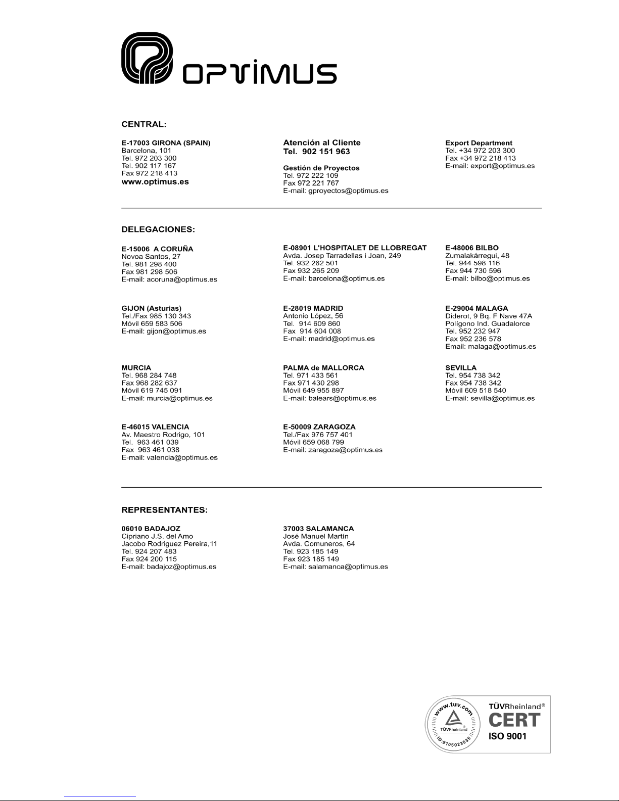
1.4. POWER SUPPLY
Use of a + 24 VDC / 3 A power supply is
recommended for the PM-812/0 (see figure 3,
number (1)).
Maximum power consumption is 2.5 A.
The power consumption varies depending on
the model and quantities of each card inserted
in the PM-812/0.
1.5. CHASSIS GROUNDING
For all P.A. systems it is very important that
there is only a single connecting point between
the signal ground and the power grounding
contact.
If the P.A. system consists of several pieces of equipment, they will probably be joined via the chassis
through a ground terminal for connection to the power supply or because they are mounted on a rack
stand.
If the grounds are also linked via the signal circuits, it is advisable to remove the jumper between the
ground and the chassis (see figure 3, number (2)) in all but one of the units.
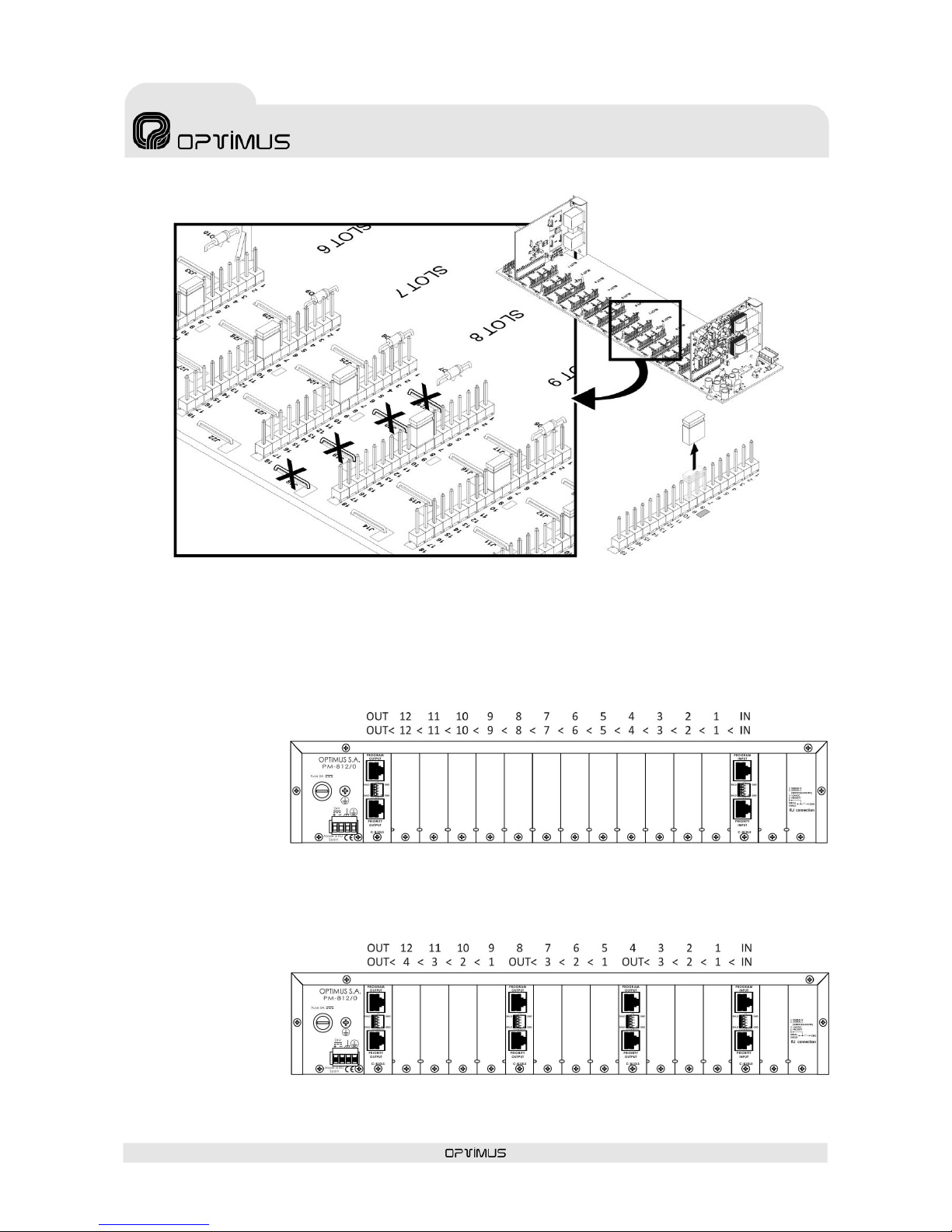
1.6. PM-812/0 BUS –INTERNAL CONFIGURATION
The default setup of the PM-812/0 consists of an input card (C-810LE), an output card (C-810LS) and a
bus with 12 free card positions.
The cards have cascade priority, so that the card located in the OUT position has the lowest priority
ranking, followed by position 12, position 11, and so on up to position IN, which has the highest priority
ranking.
If the priority of more than one input is activated, only the signal from the card in the highest priority
position reaches the channel output.
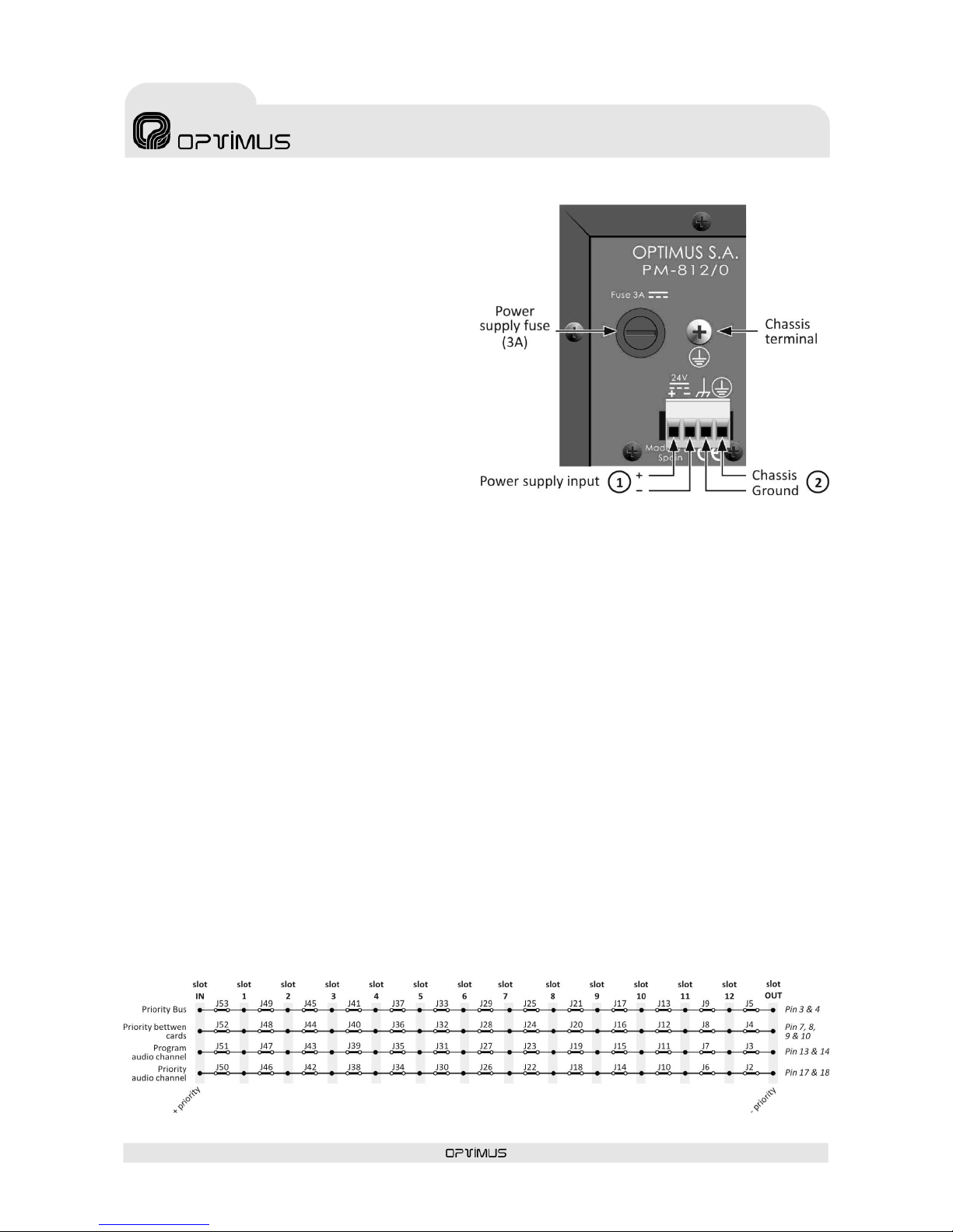
In order to make the priority system more versatile, the bus has been designed so that it can be divided
into several sections. Thus, each section (consisting of one or more card slots as required) works as an
independent module.
To do this, the four jumpers between one slot and the next one must be cut, making one part of the bus
independent from the adjacent section. Each of the four jumpers cuts a different signal (priority audio,
program audio, priority between cards and priority bus). See figures 4 and 5.