5
D6031 - SIL 3 Switch/Proximity Detector Repeater Open Collector OutputG.M. International ISM0214-2
D6031 series must be installed, operated and maintained only by qualified personnel, in accordance to the relevant national/international installation standards.
Failure to properly installation or use of the equipment may risk to damage the unit or severe personal injury.
The unit cannot be repaired by the end user and must be returned to the manufacturer or his authorized representative. Any unauthorized modification must be avoided.
Warning
Operation
D6031 module is a unit suitable for applications requiring SIL 3 level (according to IEC 61508) in safety related systems for high risk industries.
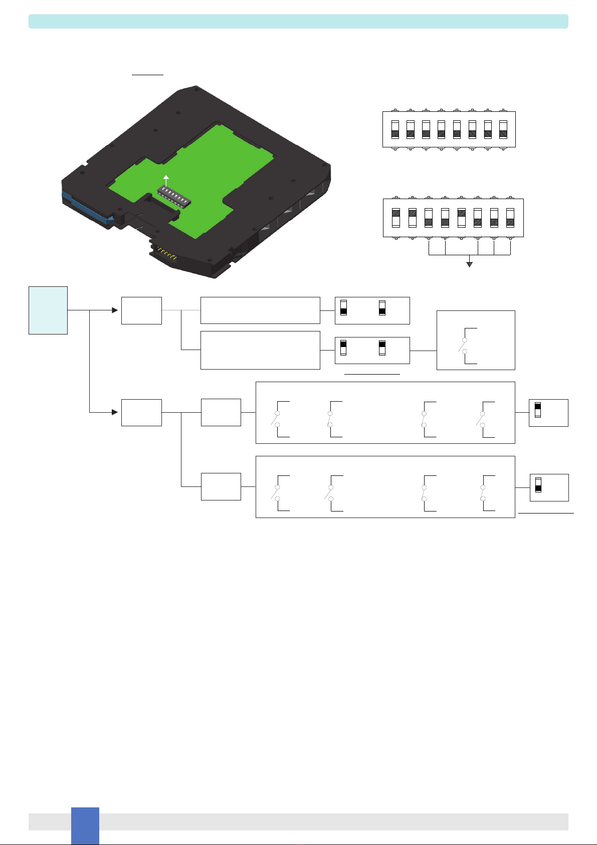
The unit can be configured for switch or proximity detector (EN60947-5-6, NAMUR), NO or NC and for NO or NC optocoupled open collector transistor output.
Each channel enables a load to be controlled by a switch, or a proximity detector.
Fault detection circuit (DIP switch configurable) is available for both proximity sensor and switch equipped with end of line resistors. In case of fault, when enabled it de-energizes
the corresponding output transistor and turns the fault LED on; when disabled the corresponding output transistor repeats the input line open or closed status as configured.
D6031D is programmable via dip switches as single input and two independent outputs. Out 2 can be programmed for output duplicating Out 1 or Fault detection Out.
In case of duplication, transistor driving can be independently configured for each output.
In case of fault output, transistor driving can be programmed as normally close or normally open.
Presence of supply power and status of output (energized or de-energized), as well as integrity or fault condition of sensor and connecting line are displayed by signaling LEDs
(green for power, yellow for status and red for fault condition).
Note: use of voltage free electrical contacts with fault detection enabled (control equipment) requires, near the switch at the end of the line a R1=1 Ktypical (470 to 2 Krange)
resistor in series and a R2=10 ktypical (5 Kto 15 Krange) resistor in parallel to the contacts in order to allow the fault detection circuit to distinguish between a condition of
contact close/open and a line open/short circuit fault.
Installation
D6031 series are Switch/Proximity Detector Interface housed in a plastic enclosure suitable for installation on T35 DIN-Rail according to EN50022, with or without Power Bus or
on customized Termination Board.
D6031 unit can be mounted with any orientation over the entire ambient temperature range.
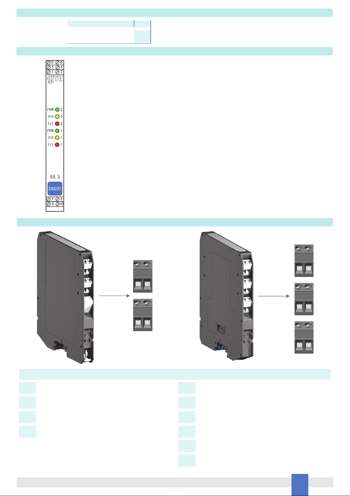
Electrical connection of conductors up to 2.5 mm² are accommodated by polarized plug-in removable screw terminal blocks which can be plugged in/out into a powered unit without
suffering or causing any damage.
The wiring cables have to be proportionate in base to the current and the length of the cable.
On the section “Function Diagram” and enclosure side a block diagram identifies all connections.
Identify the number of channels of the specific card (e.g. D6031S is a single channel model and D6031D is a dual channel model), the function and location of each connection terminal
using the wiring diagram on the corresponding section, as an example:
Connect 24 Vdc power supply positive at terminal “5” and negative at terminal “6”.
For Model D6031S connect positive output of channel 1 at terminal “1” and negative output at “2”.
For Model D6031D in addition to channel 1 connections above, connect positive output of channel 2 at terminal “3” and negative output at “4”.
For Model D6031S, in case of Proximity or Voltage free Contact, connect the wires at terminal “7” for positive and “8” for negative.
For Model D6031D in addition to channel 1 connections above, connect terminal “9” for positive and “10” for negative on channel 2.
Connect SPST output transistors checking the load rating to be within the maximum rating (100 mA at 35 Vdc (1.5 V voltage drop)).
Units must be protected against dirt, dust, extreme mechanical (e.g. vibration, impact and shock) and thermal stress, and casual contacts.
If enclosure needs to be cleaned use only a cloth lightly moistened by a mixture of detergent in water.
Any penetration of cleaning liquid must be avoided to prevent damage to the unit. Any unauthorized card modification must be avoided.
According to EN61010, D6031 series must be connected to SELV or SELV-E supplies.
Start-up
Before powering the unit check that all wires are properly connected, particularly supply conductors and their polarity, input and output wires. Check conductors for exposed wires that
could touch each other causing dangerous unwanted shorts. Turn on power, the “power on” green led must be lit, status and fault led on each channel must be in accordance with
condition of the corresponding input line. If possible close and open input lines one at time checking the corresponding status and fault LEDs condition as well as output to be correct.