Optiva QDH 04 User manual

1
H.264 4-Channel
Digital Video Recorder
QDH 04
User Guide
Version 1.0

2
Introduction
This manual is for the users who attempt to use the
H.264 4-channel Digital Video Recorder (DVR). It expresses
installation guide, connecting to peripherals, and GUI
operation. Please familiarize yourself with the contents in this
manual before using the DVR. Make sure that you have
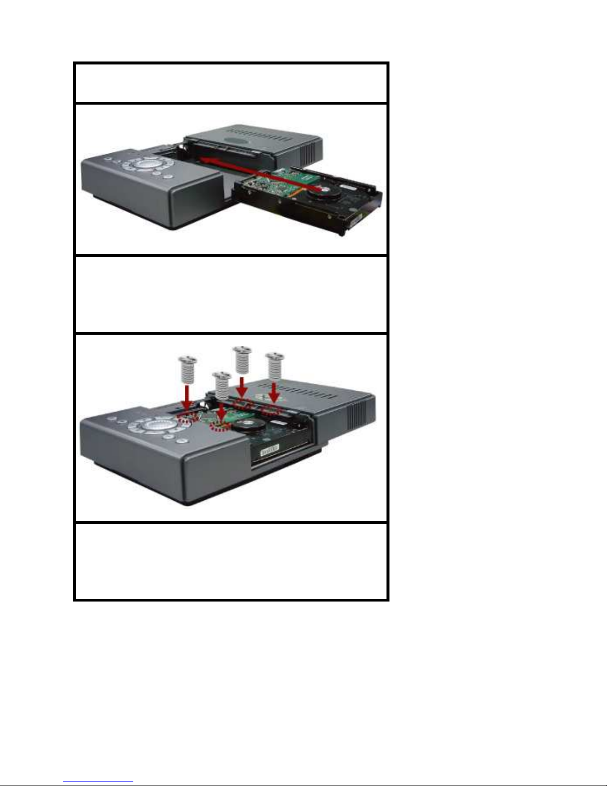
referred to an expert when opening the outer case for repair
or installing HDD. If you have any inquiries or questions on
the products, please consult to your local dealer.
About This Product
RoHS
This directive restricts the use of six hazardous
materials in the manufacture of various types of
electronic and electrical equipment.
USA
(FCC)
This device has been tested and found to comply
with the limits of ClassAcomputing device
pursuant to part 15 of the FCC rules.
Europe
(CE)
By affixing the CE marking, the manufacturer
assures that the item meets all the essential
requirements of all applicable EU directives.
Japan
(PSE)
The purpose of the Electrical Appliance and
Material Safety Law is to prevent hazards and
disturbances resulting from electrical appliances.

3
CAUTION
WARNING
To prevent fire or electric shock, do not expose this product to
rain or moisture. Dangerous high voltages are present inside
the enclosure. Do not open the cabinet. Refer servicing to
qualified personnel only.
Severe impact
or vibration may
cause
malfunction.
Not to insert any
conducting material
in the ventilation
space of product.
Avoid a direct
ray of light.
Avoid places with
strong magnetic or
electrical field, or
places near a radio
or TV.

4
Table of Contents
CHAPTER 1 UNPACKING.................................... 6
CHAPTER 2 INSTALLATION .............................. 7
2.1
DVR
O
VERVIEW
............................................... 7
2.2
R
EAR
P
ANEL
..................................................... 8
2.3
SATA
HDD
I
NSTALLATION
............................... 9
2.3
A
LARM
I
NSTALLATION
.................................... 12
CHAPTER 3 GETTING START.......................... 14
3.1
DVR
C
ONTROL
P
ANEL
................................... 15
3.2
S
TART
S
CREEN
................................................ 16
3.3
F
ULL
S
CREEN
................................................. 23
3.4
Q
UAD
S
CREEN
................................................ 24
3.5
M
AIN
M
ENU
................................................... 24
3.6
E
VENT
L
IST
.................................................... 26
3.7
P
LAYBACK
...................................................... 32

5
CHAPTER 4 MAIN MENU.................................. 38
4.1
C
AMERA
......................................................... 39
4.2
S
ETUP
............................................................. 41
4.3
R
ECORD
.......................................................... 49
4.4
A
LARM
........................................................... 57
4.5
CF
C
ARD
........................................................ 61
4.6
N
ETWORK
....................................................... 71
CHAPTER 5 IE SETTINGS................................. 73
5.1:
S
YSTEM
R
EQUIREMENTS
............................... 73
5.2:
G
ETTING
S
TART
............................................. 74
5.3
N
ETWORK
O
PERATION
:................................... 83
5.4:
DDNS
AND
PPP
O
E........................................ 87
APPENDIX A SPECIFICATION ......................... 92
APPENDIX B FAQ ................................................ 95
APPENDIX C: SUGGESTED SATA HDD........ 109

6
Chapter 1 Unpacking
Item Name Pcs
Item Name Pcs
DVR 1
Screws
(for HDD
fixing)
4
User
guide 1
Power
adaptor
(AC
100~240V
in, DC
12V out)
1
Remote
controller
1
Note: If there is any part missing or damaged,
please contact your local vendor.

7
Chapter 2 Installation
This chapter includes DVR Overview, Rear
Panel, SATAHDD & Alarm Installation.
2.1 DVR Overview
Item
Name Description
1 Control panel Control keypad and
indicators
2 CF card slot For CF card backup
3 IR receiver For infrared remote
control
4 Cover Slide cover to protect
HDD

8
2.2 Rear Panel
Item
Name Description
1 BNC out
Composite monitor
2 BNC in To connect cameras
3 VGA VGA output
4 DVI DVI-I type
5 Audio in RCAx2 (1 Vp-p)
6 Audio out
RCA (L,R) (1 Vp-p)
7 Alarm 9-pin D-
SUB male alarm I/O
port (NO)
8 LAN RJ-45 port
9 Power DC 12V

9
NOTE: If BNC, VGA and DVI outputs are all
connected to monitors, DVR will detect DVI as
the first priority, then VGA as the second, and
then BNC.
2.3 SATA HDD Installation
Follow the steps below to install HDD.
STEP 1: Lightly push the two
grooves; then pull the cover to
the open position.
STEP 2: Turn the black side of
HDD up
, and slide it into the HDD

10
bay.
STEP 3: Fix HDD by screws.
(Optional)
STEP 4: Push the cover to the
closed position.

11
NOTE: The power of HDD/ventilator will be off if
the cover is opened.
NOTE: The HDD will be started after 3 seconds
of closing cover, if HDD is not detected, warning
will be showed for 3 seconds by a message
“HDD is Non-installed !” with beep every 10
seconds. User can turn off the buzzer or leave
Live screen to quiet down.

12
NOTE: There are three reasons which may
cause the above warning message: 1) HDD is
broken 2) HDD is not installed 3) HDD is full, and
the recording mode is set as “Single-way
Recording” (refer to Section 4.3 Recording
Mode).
NOTE: If the HDD is not detected and started
within 25 seconds, it will be determined a failed
HDD.
2.3 Alarm Installation
Pin Definition

13
Pin No
Pin Definition
1 Alarm-in 1 (NO)
2 Alarm-in 2 (NO)
3 Alarm-in 3 (NO)
4 Alarm-in 4 (NO)
5 Alarm-out
6 Do not connect to
any cable.
7 Do not connect to
any cable.

14
8 Do not connect to
any cable.
9 GND
Alarm figure
Connect to NO (normal open) alarm device
Chapter 3 Getting Start
In this chapter, it introduces the control keypad of
DVR, and the definitions of icons shown on event
list and live/playback screen.

15
3.1 DVR Control Panel
NOTE: In live or playback mode, press up/down
to switch channels in full screen.

16
NOTE: In playback mode, press left/right
to rewind/fast forward the images.
3.2 Start Screen
The smart auxiliary icons on the screen will allow

17
users realizing the system status more easily.
DVR Status
1. System Status
Live
display Pause
Main
menu Fast
forward
Event list
Rewind
Playback
2. Recording Mode
No
recording
Single-way
recording

18
Continuing recording
3. Password Level
ID 0
(guest)
ID 1
(normal user)
ID 2 (administrator)
NOTE: The level status will be returned to 0 after
17 seconds without any operation or pressing
twice in live screen.
4. Language of OSD
T. Chinese
Italian
S. Chinese
Deutsch
Japanese Dutch

19
English Czech
Spanish Polish
French Russian
Hebrew
Device Status
1. CF Card Status

20
CF card is
detected
No CF card
is detected
2. HDD Cover Status
HDD cover
is closed HDD cover
is opened
3. HDD Status
HDD is
installed HDD is not
installed
4. Network Status
Network is
working Network is
not working
5. Status Bar of HDD Space
This bar shows the HDD storage & consumption
percentage
.
The estimate of recording time will
be more accurate after at least one day
Table of contents
Other Optiva DVR manuals