WWW.CNOEC.COM.CN OPTO-EDU (BEIJING) CO., LTD.
1.1.2 Packing Information for A59.2240
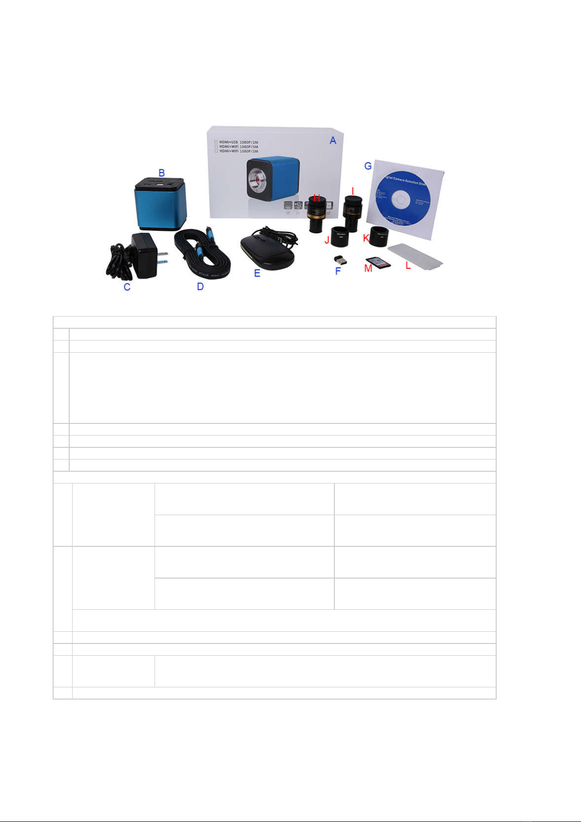
Figure 6 Packing Information of A59.2240
Standard Packing List
A
Gift box : L:25.5cm W:17.0cm H:9.0cm (1pcs, 1.43Kg/ box)
B
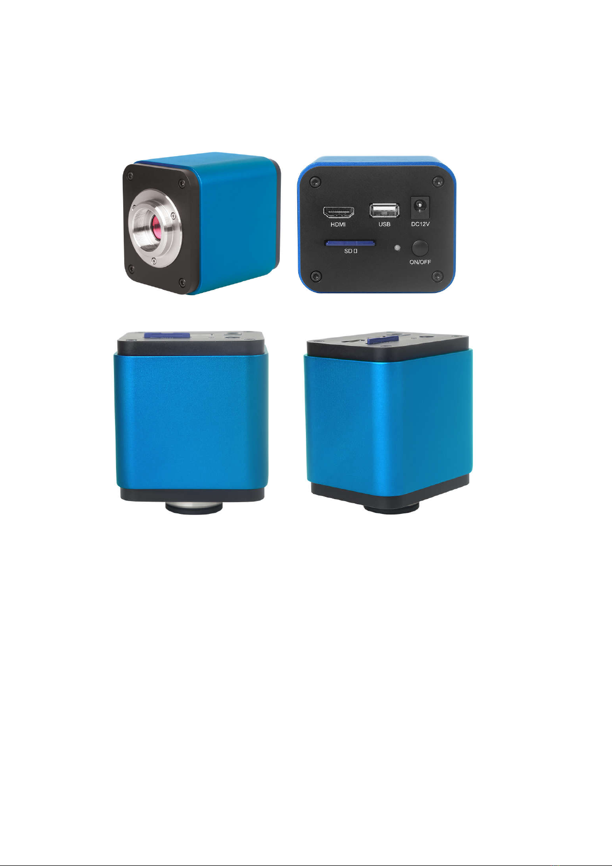
A59.2240
C
Power Adapter: Input: AC 100~240V 50Hz/60Hz, Output: DC 12V 1A
American standard: Model: GS12U12-P1I 12W/12V/1A: UL/CUL/BSMI/CB/FCC
EMI Standard:EN55022,EN61204-3, EN61000-3-2,-3, FCC Part 152 class B, BSMI CNS14338
EMS Standard:EN61000-4-2,3,4,5,6,8,11,EN61204-3,Class A Light Industry Standard
European standard:Model:GS12E12-P1I 12W/12V/1A; TUV(GS)/CB/CE/ROHS
EMI Standard:EN55022,EN61204-3, EN61000-3-2,-3, FCC Part 152 class B, BSMI CNS14338
EMS Standard:EN61000-4-2,3,4,5,6,8,11,EN61204-3,Class A Light Industry Standard
D
HDMI Cable
E
USB Mouse
F
Wireless network adapter with USB interface
CD (Driver & utilities software, Ø12cm)
H
Adjustable lens adapter
C-Mount to Dia.23.2mm Eyepiece Tube
(Please choose 1 of them for your microscope)
108001/AMA037
108002/AMA050
108003/AMA075
C-Mount to Dia.31.75mm Eyepiece Tube
(Please choose 1 of them for your telescope)
108008/ATA037
108009/ATA050
108010/ATA075
I
Fixed lens Adapter
C-Mount to Dia.23.2mm Eyepiece Tube
(Please choose 1 of them for your microscope)
108005/FMA037
108006/FMA050
C-Mount to Dia.31.75mm Eyepiece Tube
(Please choose 1 of them for your telescope)
108011/FTA037
108012/FTA050
108013/FTA075
Note: For H and I optional items, please specify your camera type(C-
mount, microscope camera or telescope camera),
ToupTek engineer will help you to determine the right microscope or telescope camera adapter for your application;
J
108015(Dia.23.2mm to 30.0mm Ring)/Adapter rings for 30mm eyepiece tube
K
108016(Dia.23.2mm to 30.5mm Ring)/ Adapter rings for 30.5mm eyepiece tube
L
Calibration kit
106011/TS-M1(X=0.01mm/100Div.);
106012/TS-M2(X,Y=0.01mm/100Div.);
106013/TS-M7(X=0.01mm/100Div., 0.10mm/100Div.)
M
SD Card(4G or 8G)