OPTO-EDU A50.7043 User manual

A50.7043
Thermal Evaporation Carbon Coater
Instruction Manual

I
Content
I. Safety Hints ...................................................................................................................................1
II. Overview ......................................................................................................................................2
2.1 Introduction.........................................................................................................................2
2.2 Index Parameters.................................................................................................................2
III. Composition................................................................................................................................3
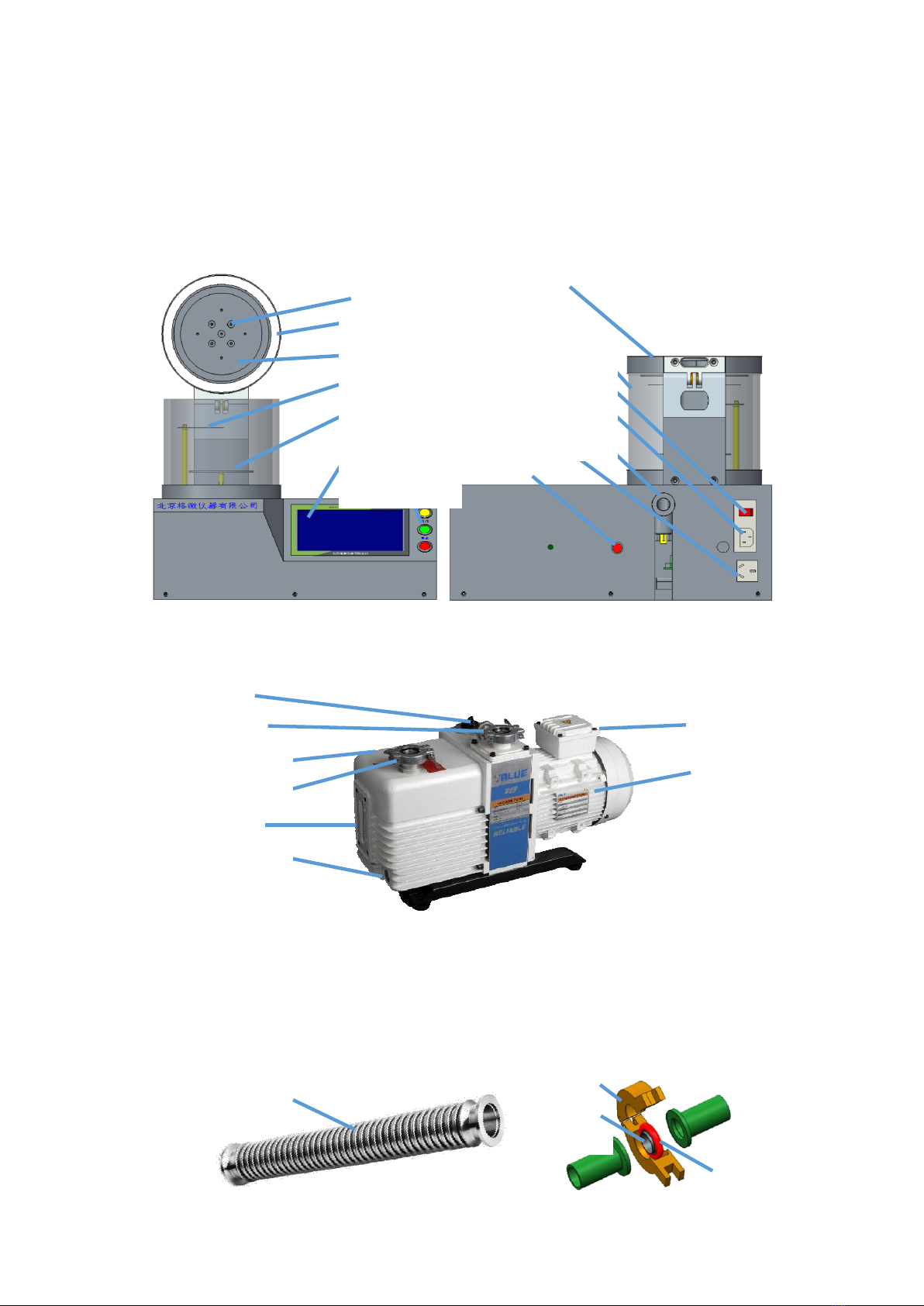
3.1 Appearance of the Mainframe and Its Components.........................................................3
3.2 Appearance and Composition of Vacuum Pump.................................................................3
3.3 Connecting Pipe Line..........................................................................................................3
3.4 Brief Introduction of Functions...........................................................................................4
3.4.1 Mainframe........................................................................................................................4
3.4.2 Function of Vacuum Pump...............................................................................................4
3.4.3 Connecting Pipe Line.......................................................................................................4
VI. Software Interface.......................................................................................................................4
4.1 Main Interface (Taking Pulse Heating Mode as An Example)............................................4
4.1.1Parameter Settings.............................................................................................................5
4.1.2 Information Hint...............................................................................................................5
4.1.3 Working Status -- Real-Time Curve.................................................................................5
4.1.4 System Status ...................................................................................................................5
4.2 System Setting Interface .....................................................................................................6
4.3 Advanced Setting ................................................................................................................8
V. Installation and Operation.............................................................................................................9
5.1 Equipment Installation ........................................................................................................9
5.1.1 Preparatory Work .............................................................................................................9
5.1.2 Pipeline Connection .......................................................................................................10
5.1.3 Circuit Connection .........................................................................................................11
5.1.4 Check .............................................................................................................................11

II
5.2 Instrument Operation Flow ...............................................................................................11
5.3 Installation and Replacement of Evaporation Source .......................................................12
VI. Matters Needing Attention........................................................................................................13
VII. Instrument Maintenance ..........................................................................................................14
VIII. Common Faults and Solutions ...............................................................................................14

I. Safety Hints
Danger
Danger
For special instruments, it is forbidden for non-professionals to disassemble the
mainframe
Danger
Danger
In the course of work, the installation part of the evaporation source will produce
high temperature, please do not touch it.
Danger
Danger
When changing the evaporation source, taking out or changing the sample, pay
attention to the high temperature of the evaporation source to avoid scalding.
Warning
Warning
Be sure to open the exhaust port before using the vacuum pump.
Attention
Attention
Do not touch the touch screen with sharp objects.
Attention
Attention
When using it for the first time, please pump the vacuum to < 1Pa (interface display)
before working.
Attention
Attention
Evaporate the baffle and glass cavity regularly, it is recommended to clean once a
month, up to once a year

II. Overview
2.1 Introduction
A50.7043 Thermal Evaporation Carbon Plating Instrument is a sample pretreatment
instrument, which is mainly used in sample preparation of analytical instruments such as scanning
electron microscope and electron probe, and can also be used in other fields that require carbon film
plating. Under a certain vacuum, the instrument gasifies the evaporation source directly by heating
the evaporation source quickly, thus escaping from the surface and finally depositing on the surface
of the sample, providing a certain degree of conductivity for the sample, which is convenient for
follow-up analysis and treatment.
2.2 Index Parameters
The device uses ARM chip as CPU and is equipped with 7-inch color touch screen. the whole
instrument has the advantages of convenient operation, intuitive interpersonal interface and stable
and reliable performance. The instrument parameters are as follows:
Input voltage
AC220V±10%, 0Hz
Evaporation source heating voltage
Max. 12V
Maximum power (main engine and
mechanical pump)
800W
Number of evaporation sources
1-4
Evaporation source
High purity carbon fiber (φ 0.8mm)
Vacuum pump
Two-stage direct connection rotary vane vacuum
pump 1L/s
Vacuum cavity
About 170 * 130mm high silicate boron glass
Working vacuum
≤ 2Pa
Diameter of sample table
Φ 95mm
Mainframe size
(length*width*height)
420x330x335 (mm)
Net weight (mainframe)
16 kg
Working environment
The temperature is 540 ℃ and the humidity is
less than 60%
Storage environment
Temperature-10 ℃, 60 ℃, humidity < 80%
Working gas
No need for external air source
Protection function
Double protection of overcurrent and vacuum
Selection and matching
Sample table rotation, sample table temperature
detection
Function expansion
Upgrade the external molecular pump unit to
high vacuum carbon plating instrument

III. Composition
A50.7043 Thermal Evaporation Carbon Plating Instrument is mainly composed of mainframe,
vacuum pump and connecting pipeline.
3.1 Appearance of the Mainframe and Its Components
3.2 Appearance and Composition of Vacuum Pump
3.3 Connecting Pipe Line
The connecting pipe is mainly composed of 304 metal bellows (lower left) and clamps (lower
right).
Electrode column
Sealing plate
Heat insulation baffle
Baffle
Sample table
Display screen
Button
Upper cover
Glass cavity
Main Switch
Total power interface
Exhaust interface
Vacuum pump power interface
Emergency deflation button
Gas ballast valve
Air inlet
Oil injection hole
Exhaust port
Observation window
Oil drain hole
Power Switch
Motor
Bellows
Clamp
Sealing ring
bracket
O-shaped
sealing ring

3.4 Brief Introduction of Functions
3.4.1 Mainframe
The mainframe is the core component of the instrument, including electrode, evaporation
source, baffle, sample table, vacuum chamber, drive circuit, control circuit, Pirani vacuum gauge,
display screen, etc.
3.4.2 Function of Vacuum Pump
Provide the required vacuum for the system.
3.4.3 Connecting Pipe Line
Connect the vacuum pump and the mainframe to form a closed vacuum environment.
VI. Software Interface
The instrument uses a 7-inch color liquid crystal capacitive touch screen as the man-machine
interface, and is equipped with three physical keys. The software and hardware interlock
programming is used to ensure the absolute safety of the operators. The operation interface is
Chinese, full digital display, intuitive and clear, clear at a glance. The interface is mainly divided
into main operation interface, setting interface, advanced setting interface (including system
debugging) and so on. All operations can be easily done in the display interface.
4.1 Main Interface (Taking Pulse Heating Mode as An Example)
Working voltage
Total number of pulse
Working voltage
Number of remaining pulses
Working vacuum
Working current
Information Hint
Working Status
System Status
Parameter Setting
Real-time curve
System setting
Operation wizard

4.1.1Parameter Settings
⚫Voltage setting (pulse and continuous mode): 0-12V continuously adjustable, step 0.1V;
pulse mode defaults to 8V, continuous mode defaults to 6V;
⚫Pulse number setting (pulse mode): 1-999 continuously adjustable, step 1;
⚫Evaporation source setting (continuous mode): 1-4 evaporation sources can be set.
4.1.2 Information Hint
⚫Working mode: continuous mode or pulse mode.
⚫Other information: real-time information that appears in the working process, such as
vacuum preparation, degassing, evaporation coating and other process information, to help
users to better use the instrument.
4.1.3 Working Status -- Real-Time Curve
During the working process, the working voltage, current, vacuum, and the number of
remaining pulses or the number of evaporation sources that have not yet been used are displayed in
real time. Click on the "real-time curve" icon, the working voltage (red), current (yellow) and
vacuum (blue) of the system will be displayed on the LCD screen in real time as a curve, making it
convenient for users to know the status of the coating process in real time.
4.1.4 System Status
Display system settings and usage information to facilitate users to understand the parameters
of the current equipment.
⚫For "operation mode", "heating mode", "evaporation source degassing", "sample table
rotation", see 4.2;
⚫Evaporation source status: when the instrument begins to vacuum, it automatically detects
the status of four evaporation sources, and indicates "available" with "green" and
"unavailable" with "gray". In the course of work, the system will also detect and update the
status of the evaporation source in real time and display it here;
⚫Film thickness control: the system provides a film thickness meter as an option to control

the coating thickness of the sample. If the module is selected, and the film thickness
control mode is adopted, "yes" is displayed, and "no" is displayed in other states;
⚫Running time: the cumulative running time of the equipment is automatically recorded by
turning on the total power supply.
4.2 System Setting Interface
⚫Operation mode: automatic or manual, click the " " button to switch the operation mode
✓Automatic: after pressing "vacuum pump on / off" (entity key), the system begins to pre-
pump vacuum, and automatically starts the evaporation carbon plating process after
reaching the set vacuum degree, until the coating is completed or all evaporation sources
fail;
(Important: to select this mode, it is necessary to complete the setting of working
parameters before the vacuum reaches the set value)
✓Manual: press this button when the vacuum reaches the preset value (when the yellow light
of "vacuum pump on / off" (entity key) is on) to start evaporation coating.
✓After switching the mode of operation, the system will automatically jump to the main
interface.
Difference: whether it is necessary to press the "work" button after the vacuum reaches
the preset value.

⚫Evaporation Source Degassing-Degassing Time
When the evaporation source begins to heat, a certain amount of gas will be released
from the surface, which may contaminate the sample or cause vacuum instability. Degassing
in advance can eliminate this effect. Select "Yes" and the evaporation source will be
preheated and degassed after starting work, and the baffle (see 3.1) will rotate automatically
to block the evaporation source and prevent contamination of the sample. After the
preheating time reaches the set "degassing time", the baffle automatically opens and enters
the coating process. The requirement for coating is not high, so you can choose "No" to enter
the state of carbon film directly to improve work efficiency.
Degassing time: 0-99s can be adjusted continuously, the step is 1s, the default is 10s.
⚫Vacuum Setting
Set the maximum pressure at which the evaporation coating process can be carried out,
and the vacuum of the system reaches this set value. If it is in automatic mode, the follow-
up work is carried out automatically; in the case of manual mode, you can press the "work"
key (entity key) for follow-up work.
⚫Screen Brightness
The brightness of the display screen can be adjusted according to the brightness of the
ambient light, which is divided into three stages to adapt to the different brightness of the
surrounding environment.
⚫Sample Table
✓Sample table rotation: automatic or manual, click the " " button to change the mode
of operation.
✓Sample table speed: low speed or high speed, click the " " button to change the
sample table speed, speed adjustable range of 4-40rpm (recommended to use the system
default).
✓Sample table manual: open or close, when the sample table rotation is set to "manual state",
this selection is valid. In manual mode, click " " to turn on or off the rotation of the
sample table. This option is only related to the "sample table rotation" setting and has nothing
to do with vacuum , etc.

⚫System Time
The system time is not adjusted on time. Set the format as 20XX (year)-XX (month)-XX
(day) XX (hours)-XX (minutes)-XX (seconds).
4.3 Advanced Setting
The parameters in the advanced settings have been set before the instrument leaves the factory,
and users generally do not need to set them. After setting, you can click "Restore Factory Settings" at
the lower right of the screen to restore the parameters!
Click " " on the system setup page, and enter "5555" in the pop-up interface to enter
the advanced settings page, as shown in the following figure:
⚫Pulse setting: set the relevant parameters when setting the pulse heating mode.
✓Positive pulse: heating evaporation source time, set range 0-10000ms (0-10s);
✓Negative pulse: the interval between two heating, set range 0-60000ms (0-60s).
⚫Maximum vacuum overshoot allowed during evaporation
In general, the vacuum degree of the system will be lower than this setting value after setting
the vacuum value at the "vacuum setting" during the working process. In individual cases, the
vacuum value of the system during the coating process will exceed the set value of "vacuum
setting". When the actual vacuum value exceeds the "vacuum setting" value, the system will not
stop working immediately, but when the actual vacuum value is greater than the "maximum

vacuum overshoot" value.
This setting improves the adaptability of the system, because in most cases, the vacuum of
the system will quickly drop below the "vacuum setting" setting.
⚫Degassing voltage: the voltage of the evaporation source during degassing, set in the range of 0-
10V;
⚫Boot evaporation source detection & detection coefficient: internal debugging use;
⚫Evaporation source: internal debugging use;
⚫High speed setting of sample table rotation
Use when sample table rotation is set to high speed on the system setup page (either manually or
automatically). The input parameter is 1-10, and the corresponding speed is 4-40rpm. The
corresponding relationship is as follows:
Coefficient
1
2
3
4
5
6
7
8
9
10
Speed (rpm)
4
4.5
5
6
7
8
10
13
20
40
⚫Heating protection parameters: internal debugging parameters.
V. Installation and Operation
5.1 Equipment Installation
5.1.1 Preparatory Work
1) Open the clamp between the air inlet and exhaust port of the vacuum pump, remove the plastic
diaphragm and gasket, and keep the air inlet and exhaust unobstructed;
2) Unscrew the filling plug, fill the lubricating oil, and the amount of oil injected see the figure on
the right.

注油塞;进气口;出气口;A向;放油塞;A向视图;建议加油位置;最高油位线;最低油位
线
Fuel injection plug; air inlet; air outlet; A direction; drain plug; A-direction view; recommended
refueling position; highest oil level line; lowest oil level line
3) Tighten the filling plug
5.1.2 Pipeline Connection
1) Install the oil mist filter on the vacuum pump outlet with the clamp provided by the vacuum pump
(note that the arrow on the filter label is facing down);
2) Connect the thick end (KF25 end) of the 304stainless steel bellows with the air inlet of the vacuum
pump with clamps and aprons provided by the vacuum pump;
3) Connect the thin end of the 304stainless steel bellows to the exhaust interface of the equipment
with the KF16 clamp and rubber ring in the accessory box.
Oil mist filter

5.1.3 Circuit Connection
1) Insert the power plug of the vacuum pump into the three-core socket on the back of the mainframe
(see 3.1);
2) Plug the power cord into the main power connector on the back of the host (see 3.1) and connect
it to the power supply (input voltage: 220V/50Hz);
3) Turn on the switch on the vacuum pump (see 3.2).
5.1.4 Check
Check the above connection to ensure that each clamp is tightened and connected correctly.
5.2 Instrument Operation Flow
1) Open the upper cover and check the white plane sealing rubber plate on the chassis and the upper
cover to ensure that the end face is clean and free of foreign bodies, and evenly apply a small
amount of vacuum grease on the end face;
2) Place the glass chamber on the white rubber sheet on the chassis and make sure the glass is
completely placed on the rubber plate.
Height adjustment of the sample table: remove the glass, loosen the hand screw under the sample
table, adjust the sample table to the appropriate height, and then tighten the screw.
3) Turn on the power and check the system status bar below the main interface. The default
parameter is "automatic operation-pulse heating-preheating and degassing-automatic high-speed
rotation of sample table";
See 4.1.4 and 4.2 to change settings if necessary.
4) Set the number of pulses, about 10 pulses of a Carbon rope fail (related to the tightness of Carbon
rope installation). If the coating is thin, it is recommended to set about 10 pulses, and if the
coating is slightly thicker, it is recommended to use about 20 pulses.
Note: the closer the sample is to the evaporation source, the higher the efficiency of carbon film
plating.
5) Place the plated sample or sample cup on the sample table;
6) Close the upper cover and make sure the upper cover is flush with the upper end of the glass and

seamless;
7) Press the vacuum pump on / off entity key:
✓When the vacuum pump starts to work, the vacuum chamber is vacuumed, and the vacuum
degree decreases gradually;
✓The system automatically detects the status of the evaporation source and displays it in the
system status bar at the bottom of the main interface (4.1.4);
✓The vacuum degree is better than the set value, and the green light of the "work" entity key
is on;
✓The sample table starts to rotate automatically;
✓The baffle closes and enters the degassing state of the evaporation source (this process is
repeated for each change of the evaporation source);
✓Degassing is complete, the baffle opens and enters the carbon plating process;
✓When the set parameters are reached, the work is completed, the green light of the "work"
entity key is off, the red light of the "stop" entity key is on, the sample table stops
automatically, and the "stop" entity key can be pressed at any time to terminate the work
process.
8) Press the vacuum pump on / off entity button again to turn off the vacuum pump;
9) Click "cavity deflation" on the touch screen to inflate the vacuum chamber;
10) When the internal and external pressure is balanced, open the top cover and take out the sample;
11) If it is necessary to continue the sample preparation, repeat 5-10 steps;
12) Work is done, and turn off the total power supply.
Note: this work process can also refer to the operation wizard that pops up on the screen after
each instrument is powered on (select "Yes" to enter the operation wizard on the "Operation
Wizard" page or not.
5.3 Installation and Replacement of Evaporation Source
The new machine has been pre-installed with 4 sets of evaporation sources and can be used
directly.
The replacement method of evaporation source is as follows:
1. Open the upper cover, loosen the 5 screws on the Carbon rope terminal, and remove the burnt

evaporation source.
2. Install the new evaporation source in the "V" shape as shown below:
1) Firstly, tighten the screws at terminal 1 to tighten the evaporation source slightly, and then
tighten the screws at terminal 4.
2) Secondly, tighten the screws at terminal 2 to tighten the evaporation source slightly, and
then tighten the screws at terminal 3.
3) finally, tighten the middle terminal screw.
* Important Note *: Make sure that the temperature at the terminal of the evaporation
source on the upper cover is close to room temperature before changing the evaporation source,
otherwise it is easy to burn!
VI. Matters Needing Attention
1. Please use the evaporation source with standard specifications to work. If other evaporation
sources are used, please consult the manufacturer.
2. Under no circumstances should the instrument be allowed to work continuously for a long
time, especially when the working mode is continuous.
3. Please pay attention to the outer surface temperature of the glass when using the instrument.
If the outer surface temperature exceeds 70 degrees Celsius (feeling hot), it is recommended
to stop for a period of time (maintain a vacuum) and wait for the glass to cool before working.
4. The instrument is unprecedented. Please be sure to check the tightness of the vacuum
chamber. It is strictly forbidden for vacuum pumps to work under high pressure for a long
time. If the vacuum of the system is less than 10Pa for more than 5 minutes, please turn off
1
2
3
4
Carbon rope
terminal *5
Carbon rope *4
1
2
3
4

the vacuum pump to check the tightness of the system.
5. Be careful when changing the sample or evaporation source and wait for the parts to cool
before starting the operation to prevent scalding.
6. Do not touch the display screen with sharp objects to avoid damage.
VII. Instrument Maintenance
1. Pay attention to the color of the vacuum pump oil (vacuum pump observation window, see
3.2 for details), the best state is to clarify and transparent, if the color is dark, or flocs appear,
it is recommended to change the vacuum pump oil as soon as possible.
2. Clean the glass cavity regularly with the donated cleaning ball to ensure that the glass cavity
has good permeability so as to observe the internal coating state during work.
3. Clean the insulation baffle regularly to maintain good cleanliness.
4. Wipe the surface of the upper and lower sealing plate regularly with dust-free cloth and
alcohol to ensure good tightness.
VIII. Common Faults and Solutions
1. The vacuum can not reach the set value for a long time.
1) Confirm that the vacuum pump is injected with random lubricating oil;
2) Check whether the vacuum pump is off (the arrow on the black knob next to the air intake of the vacuum
pump points to C);
3) Check whether the glass is placed on the rubber plate;
4) Apply proper amount of vacuum grease evenly on the surface of the rubber sheet; and
5) Take out the sample and vacuum again to see if the set value can be reached.
2. Evaporation source burns continuously for a long time / carbon plating efficiency is very low.
"Continuous burning for a long time" means that a single evaporation source has more than 30 pulses in pulse
mode and does not burn out in continuous mode for more than 20 seconds. It is necessary:
1) Check whether the evaporation source is installed properly-the evaporation source should be slightly
tightened;
2) Increase the default voltage setting value in the corresponding heating mode by 1V; and
3) Raise the height of the sample table to 10mm (see 5.2)
Note: No additional notice for
changes on the specification or
appearance due to upgrade.
ADD: F-1501 Wanda Plaza No.18 Shijingshan Road, Beijing 100043, China
TEL: 0086-10-88696020
ZIP: 100043
E-mail: sale@optoedu.com
Table of contents