OPTOGAMA FTC Series User manual

!
MANUAL v3.3
FTC
FLAT-TOP
CONVERTER
FTC series
KEY for DISCOVERIES

Table of contents
Table of contents" #....................................................................................................................................2
1. Safety requirements" #...........................................................................................................................4
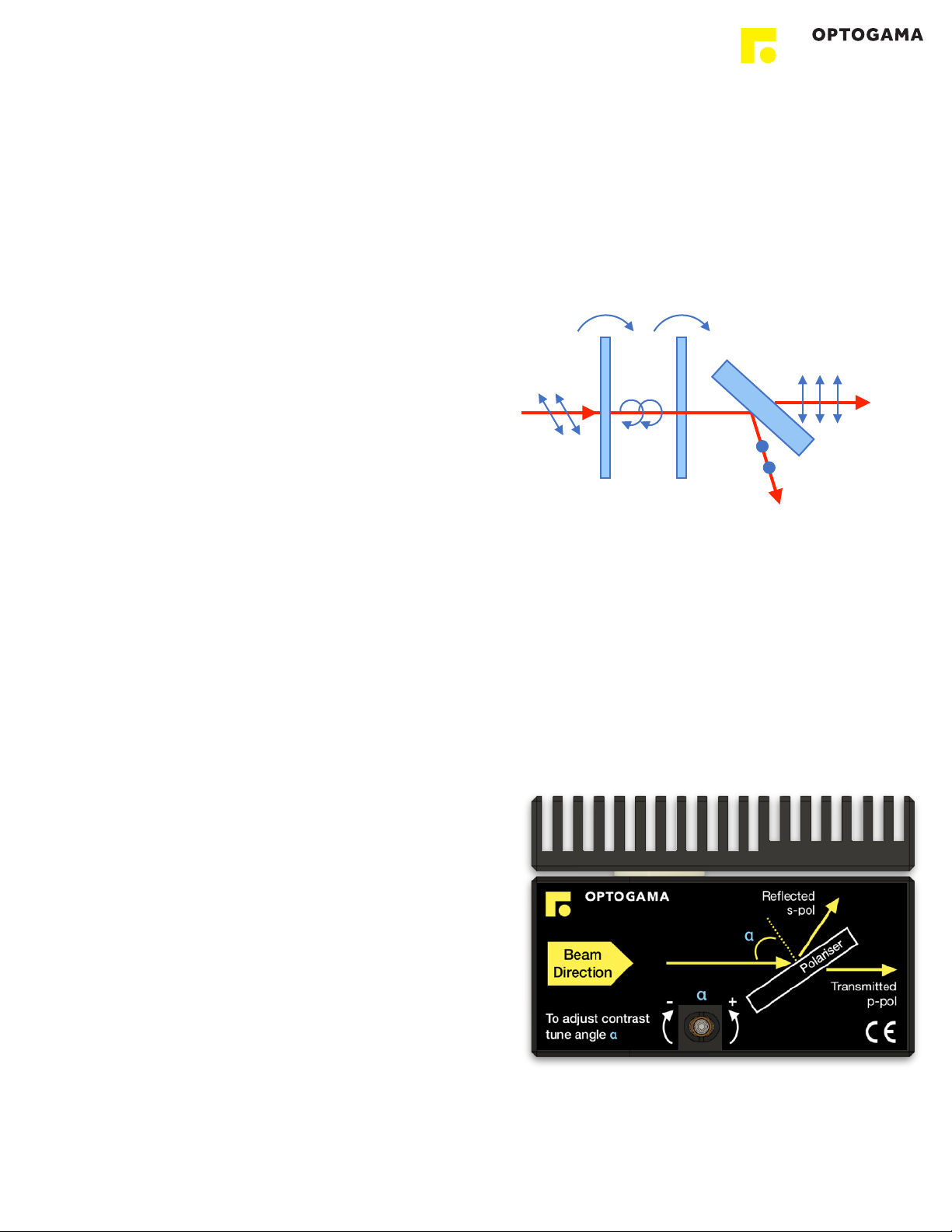
2. Operation principle" #.............................................................................................................................5
2.1.Features and advantages!..............................................................................................................................................5
2.2.Optical design!...............................................................................................................................................................5
2.3.Contrast improvement. Angle adjustment!.....................................................................................................................5
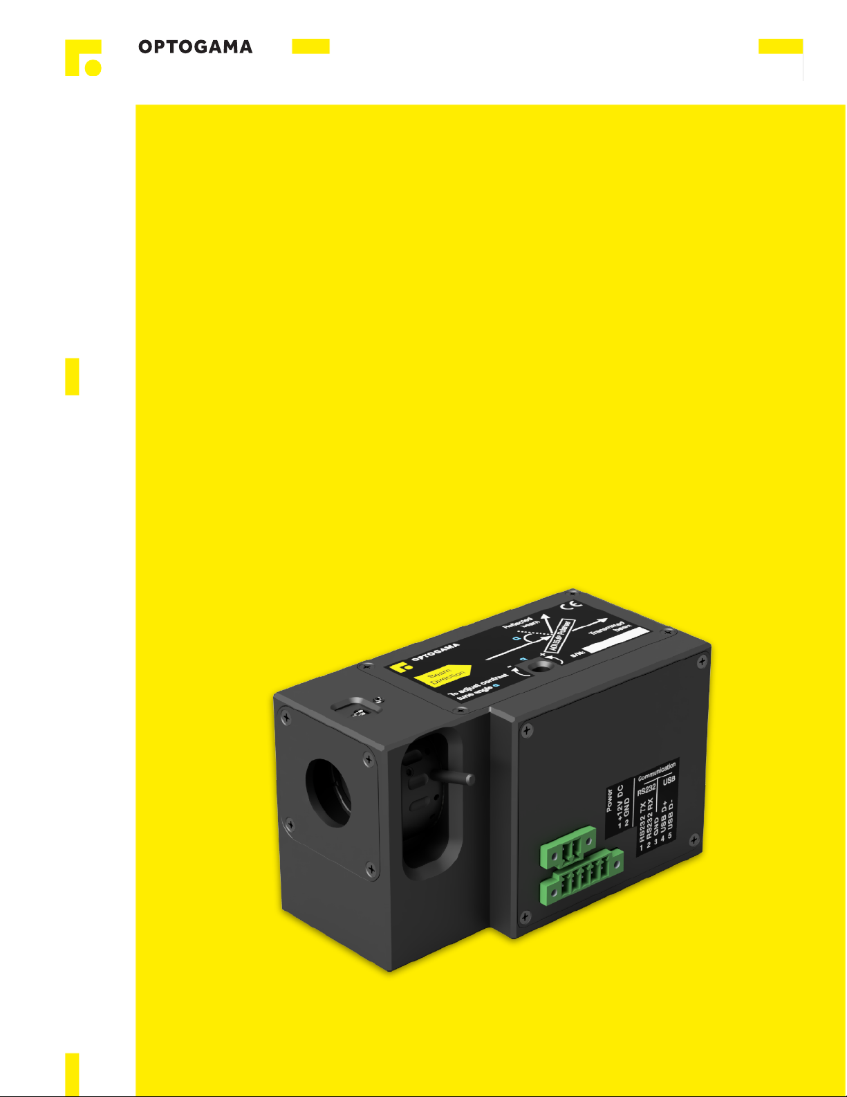
3. Product description" #............................................................................................................................6
3.1.Optical specifications!....................................................................................................................................................6
3.2.Mechanical specifications!.............................................................................................................................................6
3.3.Electronic specifications!................................................................................................................................................6
3.4.Conditions!....................................................................................................................................................................6
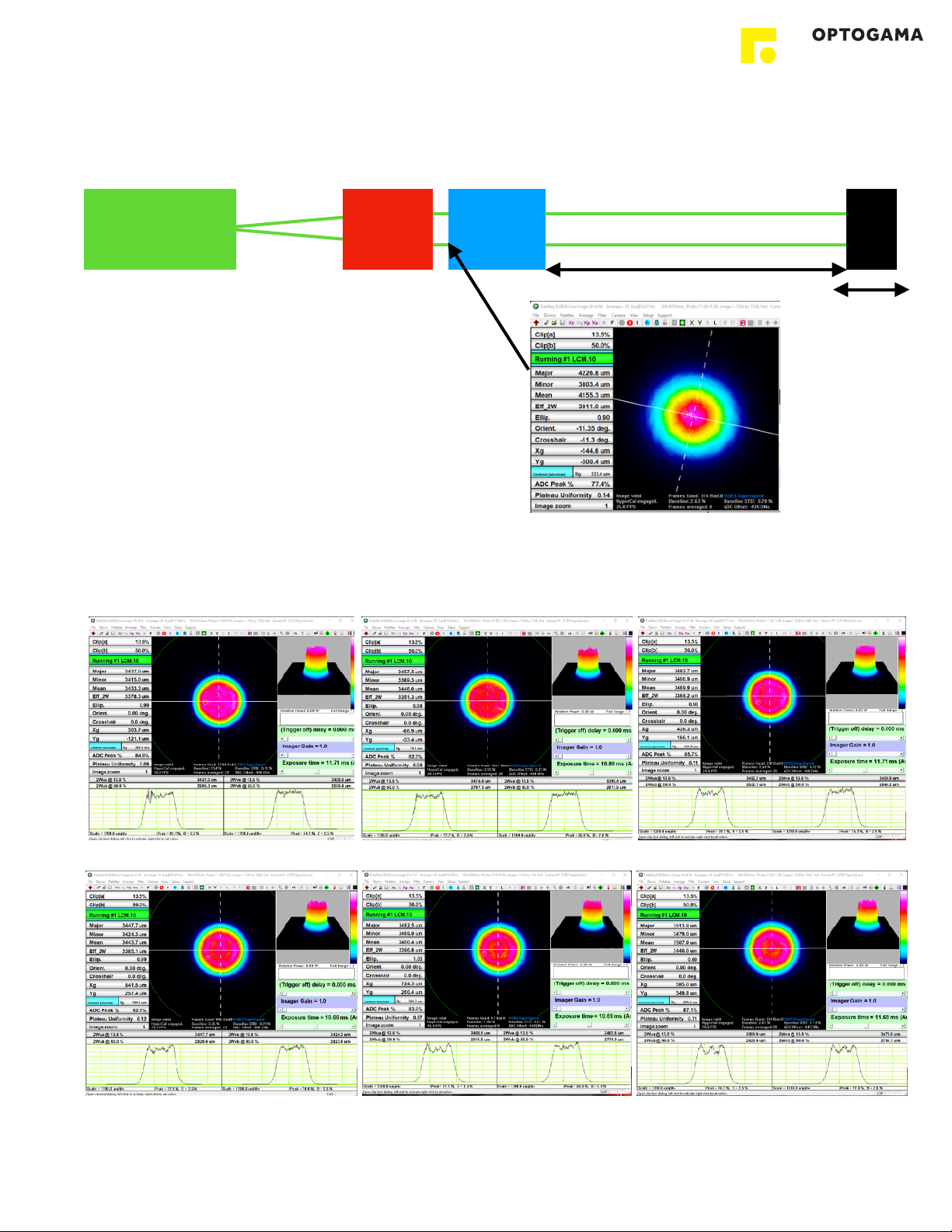
4. Measurements" #....................................................................................................................................7
4.1.Setup parameters!.........................................................................................................................................................7
4.2.Flat top mode (no expander after FTC)!..........................................................................................................................7
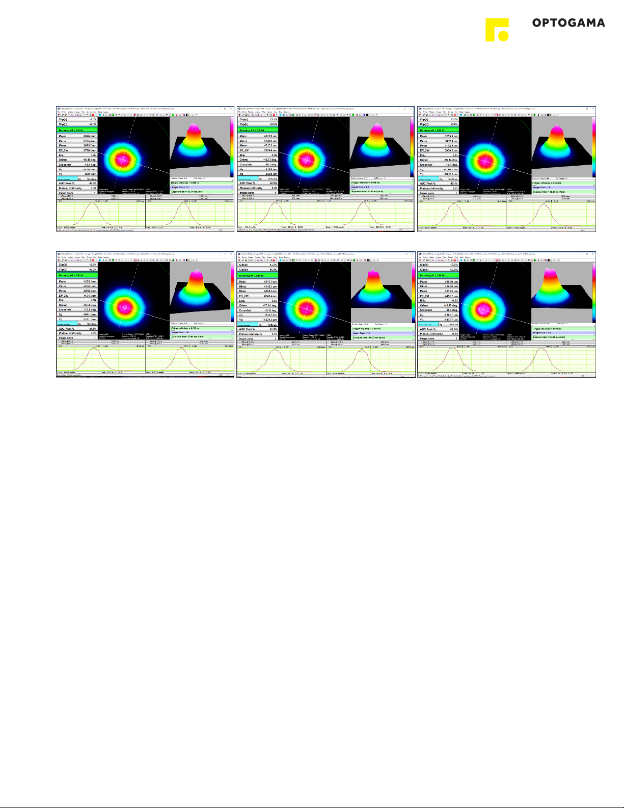
4.3.Gaussian beam mode!...................................................................................................................................................8
4.4.FTC with beam expander (2X)!.......................................................................................................................................9
4.5.FTC with beam expander (3X)!.....................................................................................................................................10
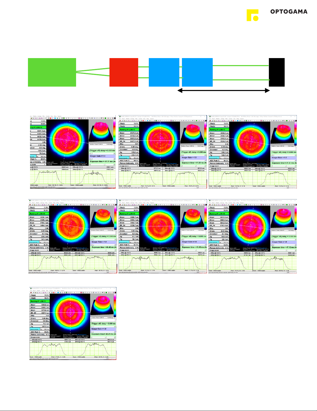
4.6.Focusing Flat Top beam (with 3X expander)!................................................................................................................11
5. Controller" #..........................................................................................................................................12
5.1.Interfaces, pinout!........................................................................................................................................................12
5.2.Voltage levels!..............................................................................................................................................................12
5.3.What’s in the box?!......................................................................................................................................................12
5.4.Available accessories!..................................................................................................................................................12
6. Software" #...........................................................................................................................................13
6.1.Minimum Hardware requirements (recommended)!......................................................................................................13
6.2.System requirements!..................................................................................................................................................13
6.3.Supported client operating systems!............................................................................................................................13
6.4.Installing the software!.................................................................................................................................................13
6.5.Using the software!......................................................................................................................................................15
6.5.1.Connection!............................................................................................................................................................15
6.5.2.Settings, calibration!................................................................................................................................................15
6.5.3.Main window!..........................................................................................................................................................16
6.6.Updating the firmware!................................................................................................................................................17
4. Commands" #......................................................................................................................................18
4.1.Interface!.....................................................................................................................................................................18
4.2.Description!.................................................................................................................................................................18
5. Troubleshooting" #................................................................................................................................21
5.1.STATUS bits explanation!.............................................................................................................................................21
5.2.Serial communication example in Python!....................................................................................................................22
6. Technical information" #.......................................................................................................................23
6.1.FTC drawings!.............................................................................................................................................................23
6.2.Power supply!..............................................................................................................................................................24
2

FTC
Integrated Flat-Top beam converter
Congratulations on your purchase of the motorised laser
power attenuator from Optogama, UAB.
***
March 2022
Copyright UAB Optogama. All rights reserved.
No part of this manual may be reproduced, transmitted in
any form without the permission of Optogama.
Claims will not be accepted and warranty repair will not be
carried out in case of improper use, incorrect service and
maintenance not according to product instructions.
Warranty claim shall not be accepted if there are any signs
of:
•Non-authorised alteration
•Disassembling of the device
•Mechanical or any external damage
•If warranty term has expired
•Serial number of the product is missing
Symbols#
CAUTION!
Sections marked with this symbol indicate dangerous
situations that can result in damage to the device,
components connected to it or operator.
NOTE:
Sections marked with this symbol indicate important
information on laser power attenuator or about this manual.
Due to constant development of our products we reserve
the right to make changes in the production line without
further notice. Up-to-date information is available at our
website www.optogama.com. If there are any further
questions, please contact us.
Optogama is not liable for damage or injury resulting directly
or indirectly from use of this product for anything other than
its intended purpose.
The motorised laser power attenuator is intended for
industrial and scientific use only. If there are any other
electrical devices connected to or used in conjunction with
the laser power attenuator, all legal regulations and technical
standards that are applied to those devices must be
observed as well.
For any technical assistance and consultation please
3

1. Safety requirements#
•All safety instructions must be followed.
•All rules and regulations concerning the safe operation of
lasers must be known and applied while installing and
operating motorised laser power attenuator.
•Even when wearing safety glasses avoid eye contact
with direct or scattered laser light while assembling,
installing and operating the device.
•The device should never be exposed to dirt, dust or
moisture.
•Before any operation make sure the device is installed
correctly and well adjusted and all cover stickers are
removed.
•Protective measures should be considered if necessary.
•Electrical safety requirements must be complied while
operating this device.
CAUTION! High laser output power may damage or destroy
optical elements.
CAUTION! The device is meant to be used with a
collimated beam. Users take full responsibility when using
the device with a highly converging beam.
CAUTION! Before increasing laser power make sure the
device is aligned and there is no beam cut. It may damage
optical elements.
4
OUTPUT$
P-pol
INPUT
COVER STICKERS MUST $
BE REMOVED BEFORE USE
!
!
REFLECTED
BEAM$
S-pol

2. Operation principle#
FTC consists of quarter-order waveplate, polarising element
and Brewster type thin film polariser. Linear polarised laser
beam is converted to circular polarised by Quarter-order
waveplate. Brewster type thin polariser passes P-polarised
and reflects the S-polarised laser beam. Switching between
Flat-top and Gaussian beam mode is achieved by motorised
rotating of the polarising element, which is located in the
incident of the laser beam.
NOTE: Before use calibration is required
NOTE: Homing is required.
CAUTION! Before increasing laser power make sure the
device is aligned and there is no beam cut. It may damage
optical elements.
2.1. Features and advantages#
• Quick change between Gaussian and Flat-top beam
• The beam profile remains Flat-Top shape along optical
axis up to 1m*#
• Integrated controller
• Designed according your laser specs.
• Clear aperture up to 15 mm#
• Quick switching time - 0.2 sec
• High damage threshold up to 10J/cm2 (10 ns @ 1064
nm)
• Conversion efficiency up to 70% (while on Flat-Top
mode)
2.2. Optical design#
FTC optical elements are coated for high LIDT (10 (J/cm2)
(10 ns @ 1064 nm) and can be applied for high power
lasers. Manual rotation of quarter wave-plate should be
done once and remain in the same position for both -
Gaussian and Flat top beam modes. Switching is achieved
by motorised rotation of polarising element.
Fig 1. Schematic explanation of optical design of Flat-top converter (FTC)
2.3. Contrast improvement. Angle
adjustment#
Incident light’s angle αshould be adjusted to improve device
contrast (± 2 deg maximum). Use HEX 1,5 key.
• Clock-wise to decrease angle
• Counter clock-wise to increase angle
Fig 2. Schematic explanation of optical design of (FTC)
S - polarised
P - polarised
Quarter
waveplate
Brewster type
polariser
Input
Output
Polarising
element
Motorised
rotation
Manual
rotation
5

3. Product description#
Flat top converter unit is all in one motorised solution for a
Gaussian beam transformation to a Flat-Top (Top Hat)
beam. The beam profile remains Flat-Top shape along
optical axis up to 1 meter.
The device consist of quartz wave-plate, space-variant
wave-plate and a high contrast polariser.
The FTC is produced in the UV, visible and NIR spectral
ranges, from 250 nm to 2000 nm.
All optical components of the FTC are made for high LIDT
and provide stable and reliable performance even using
them with high power lasers in industrial applications.
A secondary laser beam from Flat top converter unit can be
rejected to an external beam dump. The beam dump is
used for avoiding any thermal effects or stress in the
housing of the FTC device.
3.1. Optical specifications#
3.2. Mechanical specifications#
3.3.Electronic specifications#
3.4. Conditions#
Clear input aperture
Up to ø15 mm
(depends on configuration)
Clear output aperture
Up to ø15 mm
(depends on configuration)
Conversion efficiency
and Transmission
Up to 70 % (Flat-Top beam mode)
No less than 97 %
(Gaussian beam mode)
LIDT coating
>10 [J/cm2] (10 ns @ 1064 nm)
Switching time
0.2 sec
Aboslute pos. encoder
Yes, with 3.7 arcsec resolution
Flat-Top beam
The beam profile remains Flat-Top
shape along optical axis up to:
- 0.5 meter
- 1 meter (when using beam expander)
Available coatings
A. Standard wavelenghts, nm
1st harm
2nd harm
3rd harm
1064
532
355
1020 - 1040
510 - 520
343
760-840
390 - 410
-
B. Custom wavelenghts
Custom coating available
FTC
FTC with $
beam dump (BD-6)
Lenght
105 mm
105 mm
Width
53 mm
70 mm
Height
62.5 mm
62.5 mm
Interface options:
Terminal
Using commands described
in p. 12 “Commands”
Software
Using LPA software
Input voltage
DC 12 V
Transmission speed
up to 115,200 bits/s (RS-232)
full speed USB 2.0
Operating temperature
10 0C to 40 0C
Storage temperature
-15 0C to 50 0C
6

4. Measurements#
4.1. Setup parameters#
$
Laser parameters:#
Wavelength 1064nm
Beam diameter X 4.2mm, Y 3.8mm 1/e2
Flat top converter parameters:#
Wavelength 1064nm
Beam diameter 4mm 1/e2
4.2. Flat top mode (no expander after FTC)#
Z=0cm
Z=10cm
Z=20cm
Z=30cm
Z=40cm
Z=50cm
Z - distance between Flat Top Converter and CMOS camera
7
Laser source$
1064nm
Beam
expander
CCD
FTC$
4mm 1/e2$
@1064
Z

4.3. Gaussian beam mode#
Z=0cm
Z=10cm
Z=20cm
Z=30cm
Z=40cm
Z=50cm
Z - distance between Flat Top Converter and CMOS camera
8

4.4. FTC with beam expander (2X)#
Laser source$
1064nm
Beam
expander
CCD
Beam
expande
r
FTC$
4mm 1/e2$
@1064
Z
Z=10cm
Z=20cm
Z=30cm
Z=40cm
Z=50cm
Z=75cm
Z=100cm
Z - distance between Flat Top Converter and CMOS camera
9

4.5. FTC with beam expander (3X)#
Z=10cm
Z=10cm (edge)
Z=30cm
Z=30cm (edge)
Z=50cm
Z=50cm (edge)
Z=100cm
Z=100cm (edge)
Z - distance between Flat Top Converter and CMOS camera
10

4.6. Focusing Flat Top beam (with 3X expander)#
#
Laser source$
1064nm
CCD
Beam
expande
r
LENS$
2” diam.$
FL +500
FTC$
4mm 1/e2$
@1064
Beam
expander
Z=0
Z= -20cm (Flat top)
Z= -15cm (Flat top)
Z= -10cm (Flat top)
Z= -5cm (Flat top)
Z=0 (Gaussian at focus)
Z= +5cm (Flat top)
Z= +10cm (Flat top)
Z= +15cm (Flat top)
Z= +20cm (Flat top)
11

5. Controller#
5.1. Interfaces, pinout#
1. There are two contacts:
691323100005 for communication;
691323100002 for Power supply - DC 12 V
2. Connector wire gauge parameters:
Wire Gauge MAX. - 16 AWG
Wire Gauge MIN. - 24 AWG
Fig 3. Side view of FTC.
NOTE: RS-232 cable has standard DB9 female connector
at one end:
5.2.Voltage levels#
The RS-232 standard defines the voltage levels that
correspond to logical one and logical zero levels for the data
transmission and the control signal lines. Valid signals are
either in the range of +3 to +15 volts or the range −3 to −15
volts with respect to the "Common Ground" (GND) pin;
consequently, the range between −3 to +3 volts is not a
valid RS-232 level. For data transmission lines (TxD, RxD),
logic one is defined as a negative voltage, the signal
condition is called "mark". Logic zero is positive and the
signal condition is termed "space".
FTC operates on signal levels of ±5#V and can accept signal
levels of up to ±15 V. Because the voltage levels are higher
than logic levels typically used by integrated circuits, special
intervening driver circuits are required to translate logic
levels. These also protect the device's internal circuitry from
short circuits or transients that may appear on the RS-232
interface and provide sufficient current to comply with the
slew rate requirements for data transmission.
5.3.What’s in the box?#
Standard kit includes:
1. Flat top converter
2. Software
3. Power supply DC 12V (GST60A12-P1J)
4. USB cable (1.5 m)
NOTE: Other accessories must be purchased separately.
5.4. Available accessories#
Type
Contact
Connector
Communication
691323100005
691364100005
Power supply
691323100002
691364100002
1 2 3 4 5
1 2
DC 12V
RS232 and USB
PINOUT
DC 12 V
RS232
USB
1. +12 V DC
1. RS232 TX
3. GND
2. GND
2. RS232 RX
4. USB D+
3. GND
5. USB D-
Beam dump (<6W): $
(with AR/AR coated window)$
for all standard wavelengths
• 1064, 1030
• 532, 515
• 343, 355
• 247, 266
RS232 cable:$
• 1.8 m
• 5 m
• 10 m
• 15 m
12

6. Software#
6.1. Minimum Hardware
requirements (recommended)#
6.2. System requirements#
To install the application you must have administrator rights
on your computer.
To run LPA application Microsoft .NET 4.5.2 Framework or
later must be installed. The installer detects Microsoft .NET
Framework and installs it. Administrator privileges are
required for installation. Contact your network administrator
if you do not have administrator rights on the computer.
6.3. Supported client operating
systems#
•Windows Vista SP2
•Windows 7 SP1
•Windows 8
•Windows 8.1 (.NET included with OS)
•Windows 10 (.NET 4.6 included with OS)
•Windows Server 2008 SP2/R2
•Windows Server 2012 (.NET included with OS)
6.4.Installing the software#
1. Check and download the latest LPA software from our
website (www.optogama.com, www.4lasers.com) or
2. Run the downloaded software installation file. Installation
window will appear, click “Next” to continue:
3. Select “Create a desktop shortcut” if it is necessary and
click “Next”:
Review setup information and proceed the installation. To
continue click “Install”:
4. Setup will finish the installation:
Processor
1 Ghz
RAM
512 Mb
Disk space
32-bit
4,5 Gb
64-bit
4,5 Gb
13

5. Press “Finish” to end the installation:
Connect the device and controller via HD-15 cable.
6. Connect the PC and controller via USB or RS232 cable.
7. Plug in power supply to controller and AC adaptor to wall
outlet.
8. The device will be detected and configured.
9. The device installation is complete.
14

6.5. Using the software#
CAUTION! Do not switch the laser ON if the device is not
adjusted properly, it may damage or destroy optical
elements.
Launch LPA program using LPA icon on the desktop.
6.5.1. Connection#
10. Device selector window will appear. Select COM port (to
which the laser power attenuator is connected) from the
drop down menu. Press “Connect” to connect the
device or “Rescan” if your device is not visible.
Select “Filter” when device is connected via USB cable.
All other COM ports will be hidden except our device.
NOTE: When connecting via RS232 cable “Filter” must
be deselected, otherwise device will not be visible.
6.5.2. Settings, calibration#
11. Using laser power attenuator for the first time the
calibration is required. The information window will
appear:
12. For FTC calibration, move your mouse to the left side of
the window on a gear symbol from the sliding menu and
select “Settings”. Settings menu will appear:
13. To succeed calibration please follow calibration steps:
1. Set default settings
2. Home device
3. Use buttons to rotate the polarising element until
you reach Flat-top beam profile while manually
rotating Quarter wave-plate to achieve best beam
profile and transmitted energy ratio. Set current
position as Flat top position.
NOTE: Quarter wave-plate should be adjusted
and remain at the same angle for both Flat top
and Gaussian beam mode positions.
4. Rotate polarising element until you reach
Gaussian beam profile. Set current position as
LPA
15

Gaussian position. You can use a quick 45deg
rotation.
NOTE: Minor angle adjustment may be necessary
5. Select procedure after each homing:
1. Do northing - each time after homing the
device, the attenuator will remain in home
position.
2. Gaussian - each time after homing the
device, the attenuator instantly will go to
Gaussian beam mode position.
3. Flat top - each time after homing the
device, the attenuator will go toFlat top
beam mode position.
6. Choose additional measurement units if
necessary.
7. Select if automatic homing is required after
turning the device ON.
8. After finishing the calibration routine you will be
greeted into MAIN window
NOTE: After homing the device message box will appear
6.5.3. Main window#
The calibration procedure is done successfully if there is no error, device is connected and homed. The device is ready to use.
16
Settings#
Select this icon to open
calibration window to calibrate
an Flat top and Gaussian
beams and change it’s
settings
Angle value in radians#
Enter required angle value.
Press “Enter”.
Angle Slider#
Move the slider to change
angle.
Buttons for incremental
change#
Click grey button to rotate
clockwise or counter-
clockwise.
Angle value in deg#
Click double arrows to switch
units (to operate in degrees or
vice versa).
Homed$
Green - device is
homed
Connection$
Green - device is
connected
Status$
Green - if blinking device is in
motion
Error$
Red - indicates and error. Drag
cursor here to obtain error
Reconnect#
Select this icon to reconnect
the device if it is disconnected
Sliding Menu#
Drag cursor here to expand
menu
Command line#
Select this icon to open
command terminal window
Device selector tab
Connected device tab
About$
Click to open About window
for Firmware upgrader and
manual.
Quick switch#
Click button to quickly change
beam shape to gaussian or
flat top.
NOTE: must be calibrated
before use in “settings”.
Homing#
Select this icon to home the
device if necessary. Choose
“auto ON” if auto-homing is
required.

6.6. Updating the firmware#
If your device firmware version doesn’t match to software’s
firmware version while connecting to device via FTC
software you’ll be asked to update your device. If update
request pops-up, but you want to keep current firmware
and use FTC software, you must use software compatible
with that firmware version.
NOTE: Compatible software had been delivered with
device.
In order to update your device or rewrite device firmware -
USB cable must be used (update through RS232 cable is
not available).
1. Click button “Firmware Upgrader” in the About tab of
FTC software:
2. In the opened window press “Update” button. You will
be asked if you really want to update device:
After a warning device motors will be shut down and
update will start:
3. Update should be done in about a minute. If everything
went successfully message box like this should pop-up:
Now you’re ready to go.
17

4. Commands#4.1. Interface!
The device can be controlled using either USB 2.0 or
RS-232 interface. The device will switch to the required
interface upon connection of the appropriate cable.
When using the RS-232 interface, the controller
communicates on the configured baud rate (see
Command descriptions), using 8 data bits, no parity and
1 stop bit.
When the device is connected to the PC through the USB
interface, it will appear as a Virtual Serial COM port, so
all PC side communications are interchangeable between
the two interfaces.
All communications with the device are conducted by
sending literal ASCII string commands terminated with
the newline character \n. For example, the power can
be set to 10% by issuing a “FTC>PWR!_10\n” command
to which the device will respond with “FTC>PWR_10\n”.
4.2. Description#
Command
Response
Comments
Example usage
User command
Device response
Motion | Power - PWR, Angle - ANG, Target - TGT, Stop - STP
FTC>ANG?
FTC>ANG_X.XXX
Command used to get the current
angle value in degrees.
FTC>ANG?
FTC>ANG_22.143
FTC>ANG!_X.XXX
FTC>ANG_X.XXX
Command used to set the angle value
in degrees.
FTC>ANG!_22.5
FTC>ANG_22.500
FTC>FT!_X
FTC>FT_X
FTC>FT!_0 - go to gaussian position
FTC>FT!_1 - go to flat-top position
FTC>FT!_0
FTC>FT_0
FTC>FT?
FTC>FT_X
Command used to get current beam
mode position:
FTC>FT_1 - flat-top
FTC>FT_0 - gaussian
FTC>FT_0 - not in calibrated position
FTC>FT?
FTC>FT_0
FTC>STP!
FTC>STP
Command used to stop motor instantly.
Device could be used normally, homing
is not require.
FTC>STP!
FTC>STP
Homing, Calibration & Auto-go | Homing - HOME, Auto-homing - AHOME, Calibration - DEF, Auto-go - AUTOGO
FTC>DEF0!
FTC>DEF0_X.XXX
Command used to save new gaussian
beam calibration position
FTC>DEF0!
FTC>DEF0_5.240
FTC>DEF0?
FTC>DEF0_X.XXX
Command used to get gaussian beam
calibration position:
calibrated - FTC>DEF0_X.XXX
not calibrated - FTC>DEF0_null
FTC>DEF0?
FTC>DEF0_5.240
FTC>DEF0_null
FTC>DEF1!
FTC>DEF1_X.XXX
Command used to save new Flat-top
beam calibration position
FTC>DEF1!
FTC>DEF1_51.240
FTC>DEF1?
FTC>DEF1_X.XXX
Command used to get Flat-top beam
calibration position:
calibrated - FTC>DEF0_X.XXX
not calibrated - FTC>DEF0_null
FTC>DEF1?
FTC>DEF1_51.240
FTC>DEF1_null
FTC>HOME!
FTC>HOME
Command used to home the device
(motor goes to home position - TGT_0).
FTC>HOME!
FTC>HOME
FTC>AHOME!
FTC>AHOME_1
Command used to turn ON auto homing after power ON.
18

FTC>NOAHOME!
FTC>AHOME_0
Command used to turn OFF auto homing after power ON.
FTC>AHOME?
FTC>AHOME_0
Command used to get auto homing state. If 1 - Auto homing is enabled, 0 - disabled.
FTC>AUTOGO!_X
FTC>AHOME_X
Command used to set procedure after each homing:
0 - device remains in home position (TGT_0);
1 - device goes to GAUSSIAN position;
2 - device goes to FLAT-TOP position.
FTC>AUTOGO?
FTC>AHOME_X
Command used to get which procedure after each homing is selected:
0 - device remains in home position (TGT_0);
1 - device goes to GAUSSIAN position;
2 - device goes to FLAT-TOP position.
Settings | Baud rate - BAUD, Default settings - LDF
FTC>BAUD?
FTC>BAUD_baud rate
Command used to get baud rate.
FTC>BAUD?
FTC>BAUD_115200
FTC>BAUD!_baud rate
FTC>BAUD_baud rate
Command used to set baud rate.
Available speeds:
115200, 57600, 38400,
19200, 9600, 4800.
Other values are ignored.
FTC>BAUD!_57600
FTC>BAUD_57600
FTC>LDF!
FTC>LDF
Command used to load default settings. Device after this command must be:
1. Homed;
2. Recalibrated.
Information | Device state - STATUS, Wavelength - WL, Firmware v. - FW, Serial number - ID
FTC>STATUS?
FTC>X_Y
Command used to get the current state
of the device. X signifies if motor is ON.
Y signifies the error byte.
X=”1” motor is ON (enabled)
X=”0” motor is OFF (disabled)
Y = 16 bits digit with following bits:
bit0 -> driver error
bit1 -> driver high temperature warning
bit2 -> driver over temperature
bit3 -> some type of error in the driver
load
bit4 -> load warning – open load on
phase A or B
bit5 -> under voltage error
bit6 -> external memory error, working/
calibration data may be corrupted
bit7 -> reset has occurred
bit8 -> left limit switch is pressed
bit9 -> right limit switch is pressed
bit10 -> stall guard flag is active
bit11 -> motor is stand still
bit12 -> motor target velocity reached
bit13 -> target position reached
bit14 -> homing procedure was run
after the reset
bit15 -> device calibrated (bit high) if
flat-top and gaussian beam positions
defined
More info on pg. 19
FTC>STATUS?
FTC>1_0
FTC>STATUS?
FTC>0_0
FTC>STATUS?
FTC>1_2
Command
Response
Comments
Example usage
User command
Device response
19

FTC>WL?
FTC>WL_XXX
Command used to get the design
wavelength.
FTC>WL?
FTC>WL_355
FTC>FW?
FTC>_Firmware version
Command used to get firmware
version.
FTC>FW?
FTC>_1.0.0.1
FTC>ID?
FTC>_FTCXXXXXXX
Command used to get serial number.
FTC>ID?
FTC>_FTC1901001
Other | Echo, Reset, Motor ON/OFF
FTC>ECHO!
FTC>ECHO
Command used for troubleshooting.
The device echoes sent command
before sending the response.
FTC>ECHO!
FTC>TGT?
FTC>ECHO
FTC>TGT?
FTC>TGT_45602
FTC>NOECHO!
FTC>NOECHO
Command used to disable ECHO command.
FTC>RESET!
FTC>RESET
Command used to reinitialise device.
FTC>RESET!
FTC>RESET
FTC>OFF!
FTC>OFF
Command used to turn motor OFF.
FTC>OFF!
FTC>OFF
FTC>ON!
FTC>ON
Command used to turn motor ON.
FTC>ON!
FTC>ON
Command
Response
Comments
Example usage
User command
Device response
20
Table of contents
Popular Media Converter manuals by other brands

Linear Technology
Linear Technology DC2341A Demo Manual

PowerBox Systems
PowerBox Systems POWERBUS 9200 instruction manual

Whelen Engineering Company
Whelen Engineering Company E-747 Operation & installation manual

CYP
CYP EL-6010-4K22 Operation manual

Siemens
Siemens SIRIUS 3RS70 Series Original operating instructions

SIIG
SIIG CE-H20511-S1 Quick installation guide