Optoma FHDQ130 User manual

Page 1 of 74
1.5mm Pixel Pitch with SMD LEDs
FHDQ130
All-in-one LED Display
A modular system for Indoor applications
Operation Manual
2019.07
Document version 1.20

Page 2 of 74
TABLE OF CONTENTS
Dear Customer………………….…………………………………………………………………………………. 4
Important Safety Notice…………………………………………………………………………………………. 5
Accessories Supplied……………………………………………………………………………………………… 6
Spare Parts………………………………………………………………………………………………………… 7
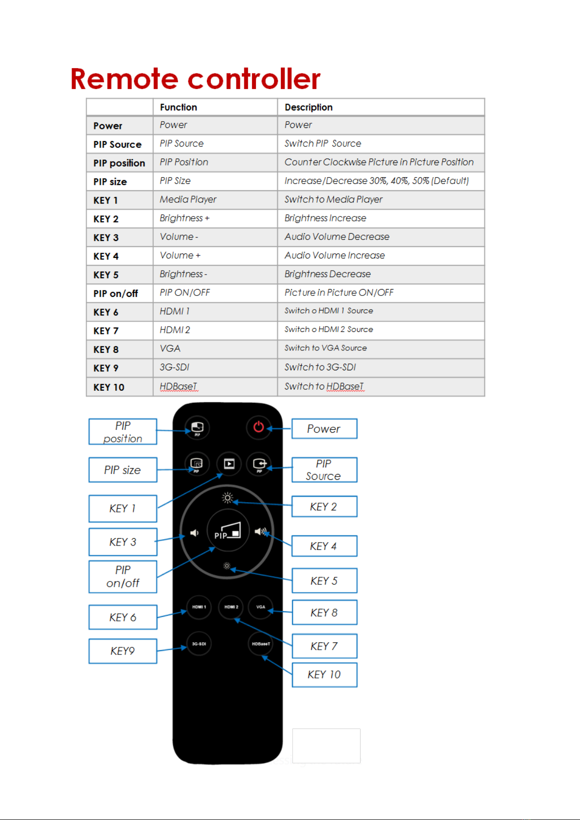
Parts and Functions………………………………………………………………………………………………. 8
Interface Specifications……………………………………………………………………………………………. 8
Assembly ……………………………………………………………………………………..................................... 10
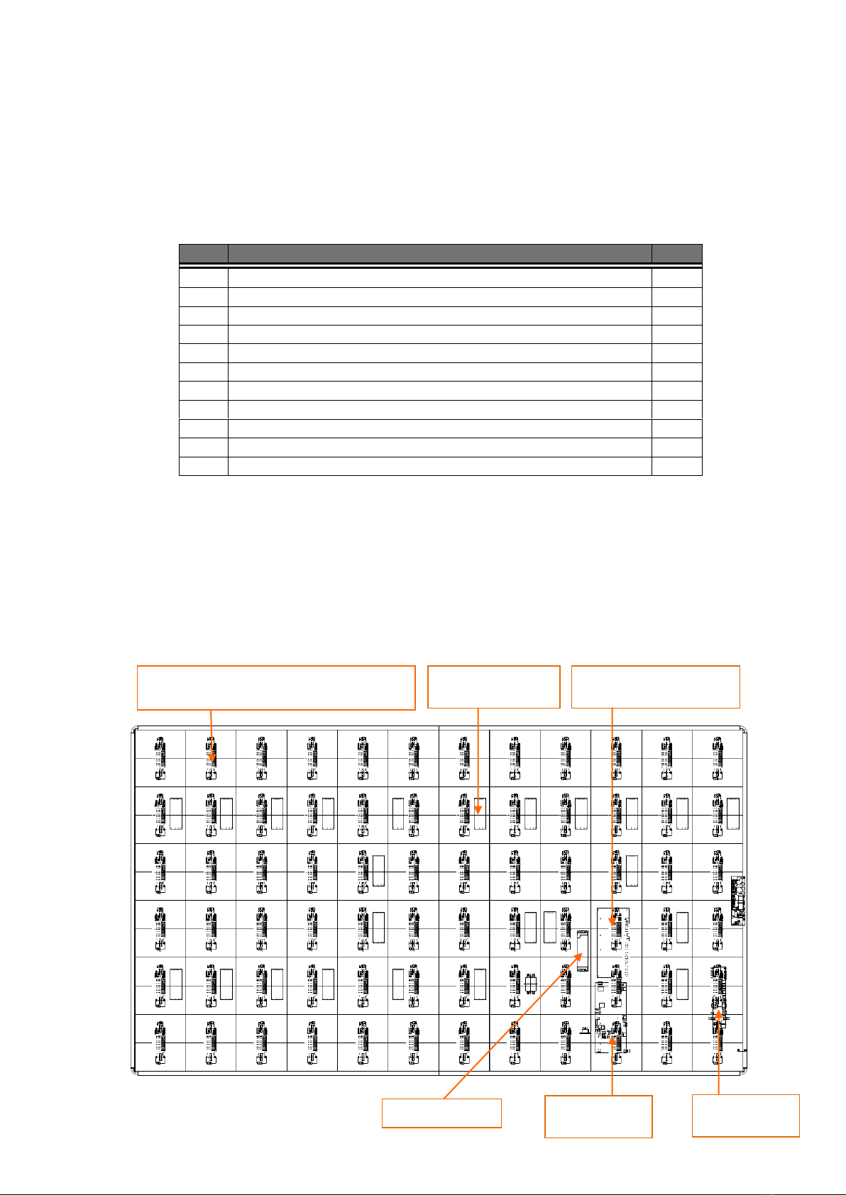
Component Placement ……………………………………………………………………………..………........... 10
Intelligent Module (IM)……………………………………………………………………………..…………........ 11
Installation…………………………………………………………………………………………………………. 12
Floor Stand……………………………………………………………………………………………………….. 12
Wall Mount………………………………………………………………………………………………………. 13
Hanging…………………………………………………………………………………………………………… 15
How to Mount and Dismount IM………………………………………………………………………………… 16
How to Assemble the Main Body…………………………………………………………………………………. 19
How to Split the Main Body into two parts……………………………………………………………………... 22
Packaging…………………………………………………………………………………………………………. 25
Electrical…………………………………………………………………………………………………………… 27
Circuit protection…………………………………………………………………………………..……................ 27
Earth leakage considerations……………………………………………………………………..………................ 27
Inrush-current and over-current considerations…………………………………………………….…................. 27
Earthing………………………………………………………………………………………..….……………....... 27
EMC Statement…………………………………………………………………………………………………… 27
FCC Statement………………………………………………………………………………………………….. 27
AC Power………………………………………………………………………..…….………................................ 28
DC Power…………………………………………………………………………………………………............ 28
Settings……………………………………………………………………………………………………………. 29
Software Installation…………………………………………………………………………………………….. 29
Software Settings………………………………………………………………………………………………… 31
USB/WIFI/LAN Connection Settings……………………………………………………………………………. 34
Basic Settings…………………………………………………………………………………………………….. 45
Send Configuration Parameters, Address Files………………………………………………………………….. 47
Program Editing………………………………………………………………………………………………….. 50
Main Toolbar……………………………………………………………………………………………………….. 50
Right-Click Menu of the Play Page………………………………………………………………………………... 50
Program Edit Toolbar……………………………………………………………………………………………… 51
Play File of Program……………………………………………………………………………………………….. 51
Program Structure………………………………………………………………………………………………… 51
Program Page……………………………………………………………………………………………………… 52
Program Window…………………………………………………………………………………………………. 53

Page 3 of 74
Program Edit Process……………………………………………………………………………………………… 54
Async Content Editing……………………………………………………………………………………………. 54
Publish Programs through USB/WIFI/LAN……………………………………………………………………….. 55
Publish Programs through U disk………………………………………………………………………………… 55
Sync Playing……………………………………………………………………………………………………….. 57
Network and Management……………………………………………………………………………………... 58
Connection and Management…………………………………………………………………………………….. 58
Add Group and Device……………………………………………………………………………………………. 58
APP Operation Instructions……………………………………………………………………………………. 59
System Overview………………………………………………………………………………………………… 59
APP Installation Instructions……………………………………………………………………………………… 59
APP Operating Instructions………………………………………………………………………………………. 59
Search Terminals…………………………………………………………………………………………………... 60
Terminal Control…………………………………………………………………………………………………. 61
Edit Program………………………………………………………………………………………………………. 63
Version Information………………………………………………………………………………………………. 65
Appendix A
Appendix B
Appendix C
Appendix D
SPECIFICATIONS……………………………………………………………………………………………
Procedure for IM Replacement …………………...……….………………………………………………
Trouble Shooting…………………...……….………………………………………..………………………
Mechanical Assembly …………………….……………………………………....…………......................
66
70
73
71

Page 4 of 74
Dear Customer,
Welcome to the family of customers. We hope that you will have many years of enjoyments from your new LED
Display.
To obtain maximum benefit from you set, please read this manual carefully before making any adjustments and retain it
for future reference.
Pictures in the manual are just for reference, the actual subject to shipment product.
If any details in this document are unclear, please contact your local representative, or the head office for more details.

Page 5 of 74
Important Safety Notice
Always ensure that the unit is properly earthed and power connections correctly made.
This equipment must be supplied from a power system providing a PROTECTIVE EARTH connection and
having a neutral connection, which can be reliably identified.
The power outlet supplying power to the unit should be close to the unit and easily accessible.
Ensure whole system power off before connect or disconnect the network cable.
Do not handle the power supply plug with wet hands.
Do not place the display on sloped or unstable surfaces, otherwise it may fall off or tip over.
Do not place any objects on top of the display.
No naked flame sources, such as lighted candles.
To prevent electric shock , do not remove cover.
No user serviceable parts inside. Refer servicing to qualified service personnel.
Don’t grab the four corners of display (after finishing assembling) when you want to move it from the floor, or
the display will become deformed and affect the alignment. You need to erect it up and move it.
Don’t grab any sheet metal of the display when you assemble the display, otherwise the sheet metal will
become deformed and affect the flatness .You can only catch the reinforcing rib.
RISK OF ELECTRIC SHOCK
DO NOT OPEN DOORS WHILE THE
EQUIPMENT IS REMAINING ON
NO USER SERVICEABLE PARTS
REFER SERVICING TO QUALIFIED
PERSONNEL ONLY

Page 6 of 74
Accessories Supplied
Item
Description
Photo
Qty.
1
AC Power Cable
14S-0GE16A-PZ-PF
1
2
AC Power Cable
14S-0UL20A-PZ-PF
1
3
AC Power Cable
14S-0BS13A-PZ-PF
4
M10 Large-headed
Screw
600-W32M10-20-PF
10
5
IM Replacement Tool
420-MAG130-A7-PF
1
6
M4x10 Flat Head Screw
600-FM0410-DC-PF
24
7
M10X16 Screw
600-HM1015-S0-PF
12
8
M8x60 Expansion Screw
600-FM0860-10-PF
50
9
M4x10 Screw(with plain and
spring washer)
60S-WM0409-DC-PF
11
10
M10 Flat Washer
630-102302-S0-PF
12
11
M10 Spring Washer
631-101526-S0-PF
12
12
M4x12mm Screw
60S-WM0412-S0-PF
8
13
Hang Plate
420-TV1212-10-PF
2
14
Mounting Plate
420-TV1212-21-PF
2

Page 7 of 74
15
Mounting Brace
420-TV1212-31-PF
1
16
USB Flash Disk
333-DISK8G-00-PF
1
17
Screwdriver
690-A25SDR-10-PF
1
18
T-Hand Hex Key
690-DEM050-1A-PF
1
19
Screwdriver
690-A15PBT-10-PF
1
20
Infrared Remote Controller
898-IRC001-00-PF
1
21
WIFI Dongle
898-00WUSB-00-PF
1
22
ANTI-STATIC GOLVES
690-ASHAND-20-PF
4
23
CORDLESS ANTI-STATIC
WRISTBAND
690-ASWA15-00-PF
4
Spare Parts
Item
Description
Photo
Qty.
1
IM
0-AM4-01G090FFEA-02P
4
2
M4x10 Flat Head Screw
600-FM0410-DC-PF
24
3
M4x10 Screw(with plain
and spring washer)
60S-WM0409-DC-PF
11

Page 8 of 74
Parts and Functions
Interface Specifications
Item
PORT
IN /OUT
SPEC and Function
1,2
INDICATOR
Standby/Running
3
STANDBY
SWITCH
Startup/Power Off
4
SWITCH
Source Switching
5,6
Br+/Br-
Screen Brightness Adjustment
7
CONFIG
Parameter Setup / Program Release
8,9
USB
USB for System Control Board
10
USB
USB for PV7
11,12
HDMI
IN
/
13
AUDIO
OUT /
14
VGA
IN /
15
RS232
/
16
3G-SDI
IN /
17
Ethernet Port
IN /
18
HDBST
IN Source Input

Page 9 of 74

Page 10 of 74
Assembly
Each FHDQ130 LED display is designed to be mounted with a specific fixing structure. Please refer to the Mechanical
Assembly (Appendix E) for the detail dimensions.
The list in table 1 is the main components of an FHDQ130 LED display. The IMs are mounted to the front surface and
the other main component locations are shown in Figure 1.
Item
Description
Qty
1
Intelligent Module (IM)
144
2
IR Receiver Board
1
3
Power and Mini Card Convertor Board(2in1)
72
4
Signal Control Board
1
5
Main Power Board
1
6
PV7 Board
1
7
System Control Board
1
8
System Core Board
72
9
4.2V /189W Switched Mode Power Supply
24
10
12V /200W Switched Mode Power Supply
1
11
EMI Filter
1
Component Placement
There are seven kinds of system board worked for the LED display, IR Receiver Board, Power and Mini Card
Convertor Board, Signal Control Board, Main Power Board, PV7 Board ,System Control Board and System Core
Board. Please refer to the description for each board in the follow sections.
FHDQ130 LED display is combined with intelligent module and case. The intelligent modules and case are fixed by
magnetic structure.
Table 1 - Major components of FHDQ130 LED display
Note: The psu output is adjustable, the actual value would subject to the label of manufacturing data
Figure 1 FHDQ130 Components
PSU 189W/4.2V
Signal Control
Board
PV7 Board
Power and Mini Card Convertor Board
(2in1)
PSU 200W/12V
System Control Board

Page 11 of 74
Intelligent Modules (IM)
The front face of the FHDQ130 LED display is fitted with 144 light emitting diode (LED) dot matrix modules known as
Intelligent Modules or IMs. Each IM is fitted with 14400 LEDs* plus associated drive electronics. Electrical connections
(low voltage power, and digital data) are made to the rear of each IM, from inside of the enclosure.
Figures 2 and 3 are showing the front and rear views of an FHDQ130 IM. For procedure of IM replacement, please
refer to Appendix B.
*Remark: each IM contains 160x90 pixels (row x column) and each pixel is composed by 3 in 1 LEDs, so there are totally
14400 LEDs fitted on the front face of an IM.
Figure 3 Intelligent Module (IM) - rear view
Figure 2 Intelligent Modules (IM) - front view

Page 12 of 74
Installation
The FHDQ130 LED display, each IM is equipped with 4 pcs guide pin, are fixed with magnetic structure and jointed
together both vertically and horizontally, so that they can form one surface of screen-configuration.
The FHDQ130 LED display is designed to be mounted on the stand. When installing, it is important to ensure that the
entire screen is correctly aligned, both vertically and horizontally.
Floor Stand
Step1. Assemble the floor stand.
Step2. Please use torque wrench to install 8 pcs M10 large-headed screws to the back side of display. The torque for
these screws is 1.2Nm.
Step3.Hand the display to the floor stand.

Page 13 of 74
Wall Mount
Step1.Use 4 pcs M4x12 screws to install one side of the mounting brace to one mounting plate. Then install the
mounting brace to another mounting plate.
Mounting Plate
Mounting Brace
M4x12mm Screw

Page 14 of 74
Step2.Drill 50 pcs 10mm mounting holes (60-65mm depth) on the wall and install 2 pcs mounting plates with 50 pcs
M8 x60 stainless steel expansion screws to the wall.
Step3. After installing the mounting plates ,hang on the LED Display.
25mm gap between panel and wall
LED Display
Wall
Mounting Plates
Expansion screws

Page 15 of 74
Hanging
Step1.Install 12pcs M10X16 screws(with a spring washer and flat washer) to the back side of LED display.
Step2.Hang the LED display. If there is a crane, hang the LED display with the help of the crane.
M10X16 Screw
M10 Flat Washer
M10 Spring Washer

Page 16 of 74
How to Mount and Dismount IM
The FHDQ130 LED display is designed to maintenance front access, When the IM is malfunction; please replace it by
the following procedure.
Note:1.Install the modules after the display is assembled, cut off the power.
2 we recommend that you should pay much attention to protect the LEDs when you maintain the
IM. Please operate with anti-static gloves.
3.Please ensure the magnetic suction tool is used correctly.
4.Please pay attention to the arrow direction on the back side of the modules.
☑
Dismount IM
Step1. Power off the LED display.
Step2. Hold the 2pcs handles, push the lock inward and pull the right handle toward outside, and then take it up.
Step3. Take the tool up and vertically fit it closely to the display surface. Please pay more attention to the direction.
lock
handles

Page 17 of 74
Step4. Pull the right handle toward inside horizontally.
Step5. Ensure that the magnet is effectively. Take the IM out from rear plate horizontally and carefully.
Step6. Put down the IM and tool together carefully onto an EPE (or other soft pad).
Step7. Push the lock toward inside and pull the right handle toward outside and lift the tool up carefully.
Mount IM
1. Take out a spare IM and locate the IM to case,please pay attention to the arrow direction on the back side of IM.

Page 18 of 74
2.Flatten the IM.
Note: When mounting an IM back, pay more attention to the guide pin which located in
corners to mount it smoothly.

Page 19 of 74
How to Assemble the Main Body
The main body of display is split into two pieces, and all the accessories are attached to each part before shipping.
Please follow below procedures to assembly two parts into a whole display.
Note: 1.Don’t grab the four corners of display (after finishing assembling) when you want to move it from the floor,
or the display will become deformed and affect the alignment. You need to erect it up and move it.
2. Don’t grab any sheet metal of the display when you assemble the display, otherwise the sheet metal will become
deformed and affect the flatness .You can only catch the reinforced rib.
3.Before assembling the display ,you need to plug the AC power cable first. There are four kinds of AC power cables
provided, Germany plug , BS plug ,UL plug and Japanese plug. Please use the screwdriver provided to loosen the screw
circled below and take out the cover. Then you can plug the AC power cable .
Step1. Take out each part of the display and put them on the floor, please make sure all the parts are well protected.
Step2.Move two parts to each others ,When the gap between two parts is about 3mm, lock the side-locks
counterclockwise, you can hear the sound when the side-locks are in place. (There are two side-locks for each panel)
Note: Before locking the side-locks, you need to loosen the side-locks clockwise in place firstly.
Left
Right

Page 20 of 74
Step3. Install 12 pcs M4 flat head screws.
Step4. Install 11 pcs M4 button head cap screws(with a plain washer and spring washer).
Step 5. Install and tighten 3 pcs black M4 flat head screws to both upper and lower side of the case.
Other manuals for FHDQ130
1
Table of contents
Other Optoma Monitor manuals