optris CSmicro LT User manual

optris®CSmicro LT/ 2WLT/ 2WLTH/ 2W2M/ 2WhsLT
¯¯¯¯¯¯¯¯¯¯¯¯¯¯¯¯¯¯¯¯¯¯¯¯¯¯¯¯¯¯¯¯¯¯¯¯¯¯¯¯¯¯¯¯¯¯¯¯¯¯¯¯¯¯¯¯¯¯¯¯¯¯¯¯¯¯¯¯¯¯¯¯¯¯¯¯¯¯¯¯¯¯¯¯¯¯¯¯¯¯¯¯¯¯¯¯¯¯¯¯¯¯¯¯¯¯¯¯¯¯¯¯¯¯¯¯¯¯¯¯¯¯¯¯¯¯¯¯¯¯¯¯¯¯¯¯¯¯¯¯¯¯¯¯¯¯¯¯¯¯¯¯¯¯¯¯¯¯¯¯¯¯¯¯¯¯¯¯¯¯¯¯¯¯¯¯¯¯¯¯¯¯¯¯¯¯¯¯¯¯¯¯¯¯¯¯¯¯¯¯¯¯¯¯¯¯¯¯¯¯¯¯¯¯¯¯¯¯¯¯
Infrared Sensor
Operators manual


CE-Conformity Optris GmbH
Ferdinand-Buisson-Str. 14
D – 13127 Berlin
GERMANY
Tel.: +49-30-500 197-0
Fax: +49-30-500 197-10
Internet: www.optris.com
The product complies with the following standards:
EMC: EN 61326-1:2006
(Basic requirements)
EN 61326-2-3:2006
Safety Regulations: EN 61010-1:2001
Laser safety: EN 60825-1:2007
The product accomplishes the requirements of the EMC Directive 2004/108/EG
and of the Low Voltage Directive 2006/95/EG.
Read the manual carefully before the initial start-up. The producer reserves the right to change the herein
described specifications in case of technical advance of the product. References to other chapters are marked
as [►...].
Warranty
Each single product passes through a quality process. Nevertheless, if failures occur please contact the customer
service at once. The warranty period covers 24 months starting on the delivery date. After the warranty is expired the
manufacturer guarantees additional 6 months warranty for all repaired or substituted product components. Warranty
does not apply to damages, which result from misuse or neglect. The warranty also expires if you open the product. The
manufacturer is not liable for consequential damage. If a failure occurs during the warranty period the product will be
replaced, calibrated or repaired without further charges. The freight costs will be paid by the sender. The manufacturer
reserves the right to exchange components of the product instead of repairing it. If the failure results from misuse or
neglect the user has to pay for the repair. In that case you may ask for a cost estimate beforehand.
optris CSmicro – E2011-08-B
1

optris CSmicro – E2011-08-B
2
Content
Page Page
Description 3Maximum Loop Impedance [2W] 29
Scope of Supply 3 Digital Mode 30
Maintenance 3 Alarm Output 32
Cautions 4 Software CompactConnect 33
Model Overview 4 Installation 33
Factory Default Settings 5 Communication Settings 34
Technical Data 7 Digital Command Set [LT] 35
General Specifications 7 Digital Command Set [2W] 36
Electrical Specifications 8 Basics of Infrared Thermometry 37
Pin Configuration 10 Emissivity 38
Measurement Specifications 11 Definition 38
Optical Charts 13 Determination of unknown Emissivities 38
CF Lens and Protective Window 17 Characteristic Emissivities 39
LED Functions 19 Appendix A – Emissivity Table Metals 40
Automatic Aiming Support 19 Appendix B – Emissivity Table Non Metals 42
Self Diagnostic 20 Appendix C – Smart Averaging 43
Temperature Code Indication 21
Mechanical Installation 22
Mounting Accessories [LT/ 2WLT15/ LT15H/ 2W2M] 23
Mounting Accessories [2WhsLT] 24
Air Purge Collars [LT/ 2WLT15/ 2WLT15H/ 2W2M] 25
Air Purge Collar [2WhsLT] 26
Further Accessories 27
Electrical Installation 28
Analog Mode 28

Description
The sensors of the optris CSmicro series are noncontact infrared temperature sensors.
They calculate the surface temperature based on the emitted infrared energy of objects [►Basics of
Infrared Thermometry].
The sensor housing of the optris CSmicro is made of stainless steel (IP65/ NEMA-4 rating) – the sensor
electronics is integrated inside the connection cable.
Scope of Supply
CSmicro incl. connection cable
Mounting nut
Operators manual
Maintenance
Lens cleaning: Blow off loose particles using clean
compressed air. The lens surface can be cleaned with a
soft, humid tissue moistened with water or a water based
glass cleaner.
PLEASE NOTE: Never use cleaning
compounds which contain solvents (neither
for the lens nor for the housing).
optris CSmicro – E2011-08-B
3

Cautions
Avoid abrupt changes of the ambient temperature.
In case of problems or questions which may arise when you use the sensor, please contact our service
department.
The sensors CSmicro are sensitive optical systems. Please use only the thread for mechanical installation.
Avoid mechanical violence on the head – this may destroy the system (expiry of warranty).
Model Overview
The sensors of the CSmicro series are available in the following versions:
Series Models Measurement range spectral Output/ Optics
response
LT 15 -40 to 1030 °C 8-14 µm Voltage output 0-5/ 10 V/ 15:1 optics
02 -40 to 1030 °C 8-14 µm Voltage output 0-5/ 10 V/ 2:1 optics
2W LT15 -40 to 1030 °C 8-14 µm Two-wire sensor (4-20 mA)/ 15:1 optics
LT15H -40 to 1030 °C 8-14 µm Two-wire sensor (4-20 mA)/ 15:1 optics/
max. ambient temperature 180 °C
hsLT -20 to 150 °C 8-14 µm Two-wire sensor (4-20 mA)/ 15:1 optics/
Detection of smallest temperature
differences (0,025 K)
2M 385 to 1600 °C 1,6 µm Two-wire sensor (4-20 mA)/ 75:1 optics
optris CSmicro – E2011-08-B
4

Factory Default Settings
The units have the following presetting at time of delivery:
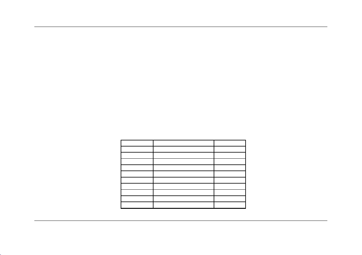
LT15/ LT02 2WLT15 2WLT15H 2W2M 2WhsLT e
Temperature range: 0...350 °C 0...350 °C 0...500 °C 385...1600 °C -20...150 °C
Output: 0...3,5 V 4...20 mA 4...20 mA 4...20 mA 4...20 mA
Emissivity: 0,950 0,950 0,950 1,000 0,950
Transmission: 1,000 1,000 1,000 1,000 1,000
Average time: 0,3 s 0,3 s 0,3 s 0,001 s 0,3 s
Smart averaging: active active active active active
Smart Averaging hysteresis: 2 °C 2 °C 2 °C 2 °C 2 °C
Ambient temperature source: internal (head)
Status-LED function: Self diagnostic
Input (IN/ OUT/ green): Communication input
Output (OUT/ yellow): mV output ------------------------ Communication output -------------------------------
Vcc adjust: inactive
Signal processing: Hold mode: off
Calibration: Gain 1,000/ Offset 0,0
Failsafe: inactive
Smart Averaging means a dynamic average adaptation at high signal edges [activation/ deactivation via software
only]. ►Appendix C
optris CSmicro – E2011-08-B
5

For a usage of the CSmicro LT for online maintenance applications (in electrical cabinets e.g.) the following
recommend settings are already included in the factory default setting (but not active):
OUT At3-state output the following settings are default:
Pre-alarm difference: 2 °C
No alarm level: 8 V
Pre-alarm level: 5 V
Alarmlevel: 0V
Service voltage: 10 V
IN/ OUT: At Alarm output (open collector) the following settings are default:
Mode: normally closed
Temp code output: activated (for values above alarm level)
Range settings: 0 °C = 0 %/ 100 °C = 100 %
Vcc adjust: If activated the following settings are default:
Output voltage range: 0-10 V
Difference mode: activated
Alarm level Alarm value (IN/ OUT pin) Vcc
1 40 °C 11 V
2 45 °C 12 V
3 50 °C 13 V
4 55 °C 14 V
5 60 °C 15 V
6 65 °C 16 V
7 70 °C 17 V
8 75 °C 18 V
9 80 °C 19 V
10 85 °C 20 V
optris CSmicro – E2011-08-B
6

optris CSmicro – E2011-08-B
7
Technical Data
General Specifications
Environmental rating IP65 (NEMA-4)
Ambient temperature Sensing head: see: Measurement Specifications
Electronics (inside cable): -20...80 °C [LT]
-20...75°C
1) [2W]
Storage temperature -40...85 °C
Relative humidity 10...95 %, non condensing
Material Stainless steel
Dimensions 28 mm x 14 mm (head) [LT/ 2WLT15/ 2WLT15H/ 2W2M]
55 mm x 29,5 mm (head incl. massive housing) [2WhsLT]
35 mm x 12 mm (electronics)
Weight 42 g [LT/ 2WLT15/ 2WLT15H/ 2W2M]
200 g [2WhsLT]
Cable length 1 m standard/ 3,5 m optional [LT/ 2WLT15/ 2WLT15H/ 2W2M]
3,5m[2WhsLT]
Position of electronics 50 cm after sensing head
Cable diameter 2,8 mm (head – electronics)
4,3 mm (electronics – end of cable)
Vibration IEC 68-2-6: 3G, 11 – 200 Hz, any axis
Shock IEC 68-2-27: 50G, 11 ms, any axis
Software (optional) CompactConnect
1) for Vcc (supply voltage) 5-12 VDC/ at Vcc > 12 VDC the max. ambient temperature of the electronics is 65 °C

optris CSmicro – E2011-08-B
8
Electrical Specifications
Used pin Function LT 2W _
OUT IN/ OUT
x Analog 0-5 V
1) or 0-10 V 2)/ scalable 4-20 mA/ scalable (current loop
between Power and GND pin)
x Alarm output voltage adjustable; N/O or N/C output current adjustable; N/O
or N/C (current loop between
PowerandGNDpin)
x Alarm 3-state alarm output (three voltage level -
for no alarm, pre-alarm, alarm)
x Alarm programmable open collector output programmable open collector
[0-30 V DC/ 50 mA]
4) output [0-30 V DC/ 500 mA]
x Temp. Code Temp. Code Output (open collector) Temp. Code Output (open
[0-30VDC/50mA]
4) collector) [0-30 V DC/ 500 mA]
x Input programmable functions: programmable functions:
-external emissivity adjustment -triggered signal output and
-ambient temperature compensation peak hold function
5)
-triggered signal output and peak hold
function
5)
x x Serial digital
3) uni- (burst mode) or bidirectional uni- (burst mode) or
bidirectional
Output impedances min. 10 kload impedance max. 1000 loop impedance
Current draw 9 mA 4-20 mA
Power supply 5...30 VDC 5...30 VDC

optris CSmicro – E2011-08-B
9
Status LED green LED with programmable functions:
alarm indication (threshold independent from alarm outputs)
automatic aiming support
self diagnostics
temperature code indication
Vcc adjust mode 10 adjustable emissivity and alarm values by variation of supply voltage/
Service mode for analog output [LT only]
1) 0...4,6 V at supply voltage 5 VDC; also valid for alarm output
2) only at supply voltage 11 V
3) inverted RS232, TTL, 9,6 kBaud
4) 500 mA if the mV output is not used
5) High level: > 0,8 V/ Low level: < 0,8 V

Pin Configuration
white Power Power supply
yellow OUT Analog output/ TxD (5 V)/ Alarm output
green IN/ OUT Analog input/ RxD (5 V)/ Open collector output
brown GND Ground ()
black Shield Shield
white Power Current loop (+)/ Alarm output
yellow OUT TxD (5 V)
green IN/ OUT Trigger input/ RxD (5 V)/ Open collector output
brown GND Current loop (-)/ Ground ()
black Shield Shield
You will find a detailed description of the different sensor connections in chapter ►Electrical Installation.
optris CSmicro – E2011-08-B
10

optris CSmicro – E2011-08-B
11
Measurement Specifications
LT15/ LT02 2WLT15 2WLT15H e
Temperature range IR -40...1030 °C -40...1030 °C -40...1030 °C
(scalable via software)
Ambient temperature (sensing head) -20...120 °C -20...120 °C -20...180 °C
Spectral range 8...14 µm 8...14 µm 8...14 µm
Optical resolution 15:1/ 2:1 15:1 15:1
CF-lens (optional) 0,8 mm@ 10 mm/ 0,8 mm@ 10 mm 0,8 mm@ 10 mm
2,5 mm@ 23 mm
Accuracy1) ±1,5 °C or ±1,5 % 2) ±1,5 °C or ±1,0 % 2) ±1,5 °C or ±1,0 % 2)
Repeatability1) ±0,75 °C or ±0,75 % 2) ±0,75 °C or ±0,75 % 2) ±0,75 °C or ±0,75 % 2)
Temperature coefficient 3) ±0,05 K/ K or ±0,05 %/ K (whichever is greater)
Temperature resolution 0,1 K 0,1 K 0,1 K
Response time 30 ms (90 % signal) 30 ms (90 % signal) 30 ms (90% signal)
Warm-up time 10 min 10 min 10 min
Emissivity/ Gain 0,100...1,100 (adjustable via software)
Transmissivity 0,100...1,000 (adjustable via software)
Interface (optional) USB programming interface
Signal processing Average, Peak hold, Valley hold (adjustable via software)
1) at ambient temperature 235 °C, whichever is greater; Epsilon = 1; Response time 1 s
2) at object temperatures > 0 °C
3) for ambient temperatures <18 °C and >28 °C

optris CSmicro – E2011-08-B
12
2WhsLT 2W2M e
Temperature range IR -20...150 °C 385...1600 °C
(scalable via software)
Ambient temperature (sensing head) -20...75 °C -20...125 °C
Spectral range 8-14 µm 1,6 µm
Optical resolution 15:1 75:1
Accuracy1) ±1 °C or ±1 % 3) ±(0,3 % of reading + 2 °C) 2)
Repeatability1) ±0,3 °C or ±0,3 % 3) ±(0,1 % of reading + 1 °C) 2)
Temperature coefficient 5) ±0,05 K/ K or ±0,05 %/ K (whichever is greater)
Temperature resolution 0,025 K
3) 4) 0,1 K
Response time 150 ms (90 % signal) 10 ms (95 % signal)
Warm-up time 10 min -
Emissivity/ Gain 0,100...1,100 (adjustable via software)
Transmissivity 0,100...1,000 (adjustable via software)
Interface (optional) USB programming interface
Signal processing Average, Peak hold, Valley hold (adjustable via software)
1) at ambient temperature 235 °C; Epsilon = 1; Response time = 1 s
2) at object temperatures > 450 °C
3) at object temperatures > 20 °C
4) at time constants > 0,2 s
5) for ambient temperatures <18 °C and >28 °C

Optical Charts
The following optical charts show the diameter of the measuring spot in dependence on the distance
between measuring object and sensing head. The spot size refers to 90 % of the radiation energy.
The distance is always measured from the front edge of the sensor housing/ CF-lens holder/ air purge.
The size of the measuring object and the optical resolution of the infrared thermometer determine the maximum
distance between sensing head and measuring object.
In order to prevent measuring errors the object should fill out the field of view of the optics completely.
Consequently, the spot should at all times have at least the same size like the object or should be smaller than
that.
D = Distance from front of the sensing head to the object
S = Spot size
The D:S ratio is valid for the focus point.
LT15/ 2WLT15/ 2WLT15H/ 2WhsLT D:S = 15:1
optris CSmicro – E2011-08-B
13

LT15/ 2WLT15/ 2WLT15H/ 2WhsLT with CF lens (0,8 mm@ 10 mm)
LT02 D:S = 2:1
optris CSmicro – E2011-08-B
14

LT02 with CF lens (2,5 mm@ 23 mm)
2W2M SF D:S = 75:1
optris CSmicro – E2011-08-B
15

2W2M CF D:S = 75:1/ D:S Far field = 14:1
If the CF lens (ACCTCFHT or ACCTCFHTE) is used in connection with 2W2M units (SF or CF optics) the focus is
shifted to a distance of 11 mm.
optris CSmicro – E2011-08-B
16

CF Lens and Protective Window
If the CF lens is used, the
transmission has to be set to 0,78
[LT/ 2WLT].
The optional CF lens allows the measurement of very small objects.
The minimum spot size depends on the used sensing head. The
distance is always measured from the front edge of the CF lens
holder or laminar air purge collar. The installation on the sensing
head will be done by turning the CF lens until end stop. To combine it with the 2WhsLT model please use the
version with external thread M12x1.
Versions Overview:
ACCTCF CF lens for installation on sensing head [LT/ 2WLT]
ACCTCFHT CF lens for installation on sensing head [2W2M]
ACCTCFE CF lens with external thread for installation in massive housing [LT/ 2WLT]
ACCTCFHTE CF lens with external thread for installation in massive housing [2W2M]
For protection of the sensing head optics a protective window is available. The mechanical dimensions are
equal to the CF lens. It is available in the following versions:
ACCTPW Protective window for installation on sensing head [LT/ 2WLT]
ACCTPWHT Protective window for installation on sensing head [2W2M]
ACCTPWE Protective window with external thread for installation in massive housing [LT/ 2WLT]
ACCTPWHTE Protective window with external thread for installation in massive housing [2W2M]
If the protective window is used, the
transmission has to be set to 0,83 [LT/
2WLT] or 0,93 [2W2M].
optris CSmicro – E2011-08-B
17

CF lens: Laminar air purge with integrated CF lens with external thread:
ACCTCF/ ACCTCFHT CF lens: ACCTCFE/ ACCTCFHTE
Protective window: ACCTAPLCF/ ACCTAPLCFHT Protective window with external
ACCTPW/ACCTPWHT thread:
ACCTPWE/ACCTPWHTE
To change the transmission value the optional USB-Kit (including software) is necessary.
optris CSmicro – E2011-08-B
18
This manual suits for next models
4
Table of contents
Other optris Accessories manuals
Popular Accessories manuals by other brands

SICK
SICK PowerProx Micro WTT2SL Series operating instructions

Panasonic
Panasonic DVCPRO AJ-BS901P operating instructions

Lowrance
Lowrance LDT-3002 Install and operation instructions

Keis
Keis Heated Body Warmer operating instructions

X10
X10 HawkEye MS13A Set up and operating instructions

sparoom
sparoom Pixie instructions