Electrical Specifications
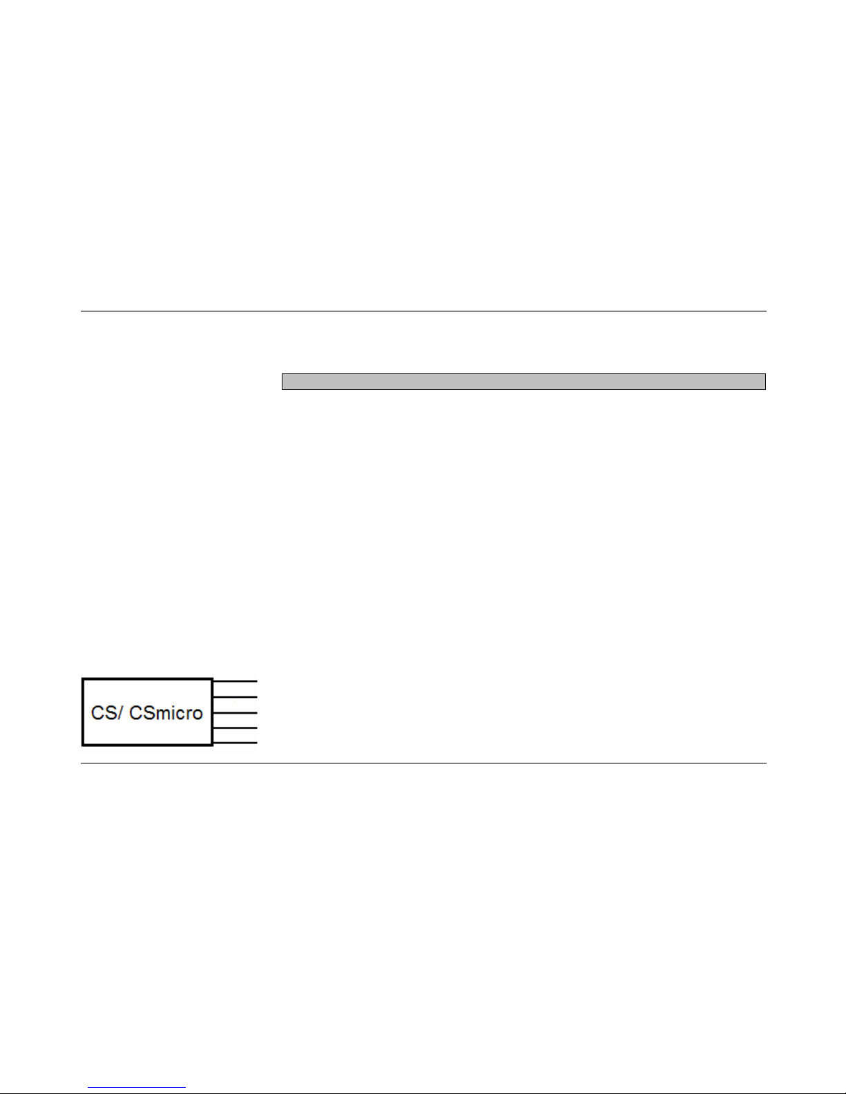
CS CSmicro
Output [used pin] aonly alternatively selectable e
Analog [OUT] 0-5V
1)
or 0-10V2)/ scalable 0-5V
1)
or 0-10V2)/ scalable
Serial digital
3)
[OUT+IN] uni- (burst mode) or bidirectional uni- (burst mode) or bidirectional
Alarm [OUT] output voltage adjustable; N/O or N/C output voltage adjustable; N/O or N/C
Additional features LED alarm indication/ Programmable open collector output
LEDaimingsupport 24VDC/50mA[INpin]
Output impedances min. 10kΩload impedance min. 10kΩload impedance
Input programmable functional input on green IN pin for:
external emissivity adjustment [0V ►ε=0,1 │5V ►ε=1,1]
ambient temperature compensation [0V ►-20°C │5V ►350°C]
trigger (reset of hold functions) [5V at IN pin resets the selected hold function]
Current draw 9mA (12…28V DC)/ 15mA (5V DC) 9mA
Power supply 5…7V DC or 12…28V DC 5…28V DC
1)
0…4,6V at supply voltage 5V DC
2) only at supply voltage ≥11V
3)
inverted RS232, TTL, 9,6 kBaud
white PS Power supply
optris CS/ CSmicro – E2007-03-A
6
yellow OUT Analog output/ TxD (5V)/ Alarm output
green IN Analog input/ RxD (5V)/ Open collector output (CSmicro only)
brown GND Ground (⊥)
black Shield