Opus Technologies LD Series User manual

EN
Installation and user
manual
LD 1.0 / 2.0 / 3.0
Class D loop amplifier LD Séries
PERIMETER LOOP AMPLIFIER

User Manual 2
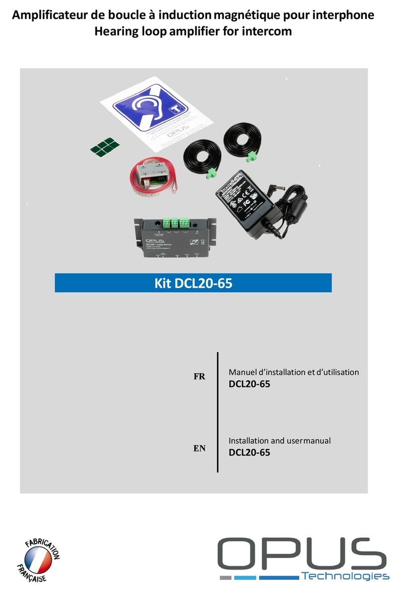
User Guide EN 1
1. Intro 4
1.1 Purpose 4
1.2 Targeted audience 4
1.3 Warnings 4
1.4 Icons 4
2. Presentation of the amplifier 5
2.1 Description 5
2.2 The range 5
2.2 Packing list 5
2.3 OP-R (option) 5
2.4 Advices and safety 6
3. Technology presentation 7
3.1 What is an induction loop system? 7
3.2 Working principles 7
4. Controls, Connections and Settings 8
4.1 Controls 8
4.2 Multi-loop output 8
4.3 Front panel and settings 9
4.4 Back side and settings 10
4.5 Racking 11
4.6 Adjustments and connections 12
4.7 Connections of two amplifiers 12
TABLE OF CONTENTS| EN
LD Series | Installation and user manual |

User Manual 3
5. Setting up 17
5.1 Setting a single loop 17
5.2 Setting up a master amplifier and a slave amplifier 17
5.3 Locking settings 17
5.4 Metal loss compensation adjustment 18
5.5 Operation of the fault contact 18
5.6 Audio Input 18
6. Understanding and planning of a loop system 19
6.1 Preamble 19
6.2 Basic principles 19
6.3 The different types of implantation 20
7. The magnetic induction loop 22
7.1 Placing the loop 22
7.2 Thickness of the wire 22
7.3 The magnetic field 22
7.4 Connections 22
7.5 Loop layouts simulation 23
8. Installation constraints 26
8.1 External overspill 26
8.2 Distortion due to metal 26
Certificate of conformity to IEC 60118-4 standard 27
TABLE OF CONTENTS| EN

User Manual 4
ENGLISH
1. Intro
Thank you for have purchasing an Opus
Technologies Induction Loop Amplifier.
Please take a few moments to read this manual. It
will ensure you the best use of the product and
many years of service.
1.1 Purpose
The user manual provides the necessary information
for installing, configuring and using an LD series
amplifier.
1.2 Targeted audience
The installation and user's manual is intended for
installers and users of LD Opus Technologies series
amplifiers.
1.3 Warnings
This user guide relates to three types of alerts.
The type of alert is closely related to the effect that
may occur if this one is not observed. These alerts,
ranked in ascending order of severity, are as follows:
Note
Additional information. Generally, the non-
observance of a Note type alert does not lead to any
material or bodily injury.
•Attention
Failure to observe a caution alert may result in
property damage.
•Warning
Failure to observe a warning alert can result in
severe personal injury and property damage.
1.4 Icons
1.4.1 Icons and notes
Icons used with notes provide additional information
about the note.
See the following examples:
1.4.2 Icons of attention, warning and danger
The icons used in combination with Attention,
Warning and Danger indicate the type of risk
present.
See the following examples:
Note:
General icon of the notes
Note:
Symbol referring to the
indicated information source.
Attention, warning, danger :
Electrocution risk icon.
Attention, warning, danger :
General icon of precautionary statements,
warnings and dangers.
Attention, warning, danger :
Risk icon of electrostatic discharge.
LD Series | Installation and user manual |

User Manual 5
2. Presentation of the amplifier
2.1 Description
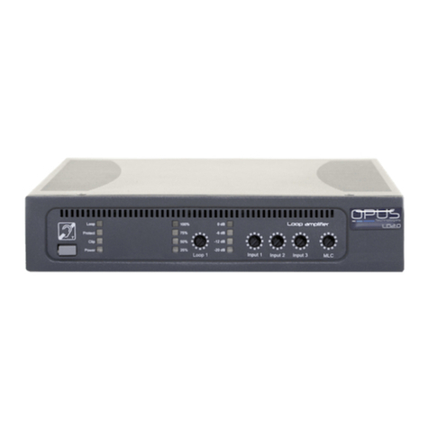
The LD Series range includes induction loop
amplifiers made to equip voiced rooms for
people with hearing loss.
The LD Series has been developed with strict and
rigorous specifications that allow us to offer a 5
year warranty. The products have been designed
with options to facilitate their use and their
installation.
Product photo Figure 1
Perimeter amplifiers composed of LD1.0, LD2.0
and LD3.0 cover different surfaces described
below.
2.2 The range
The LD1.0, LD2.0 and LD3.0 Opus Technologies
are new generation of induction loop amplifiers
and French manufacture.
The amplifiers, are the most compact on the
market while offering the necessary features
(AGL, MLC, compressor, etc.) to ensure
installation for rooms ranging from 100m² to
1000m² :
· LD 1.0 covers 250 m² - max width: 10m
· LD 2.0 covers 450 m²- max width : 15m
· LD 3.0 covers 1000 m² - max width : 20m
These coverage data are indicative, they meet
the international standard IEC-60118-4.
However, depending on the configuration of the
room (step, height installation, etc.) these room
widths do not meet the requirements of IEC-
60118-4,so it is important to call a specialist.
You can also use our simulation software or get
closer to your local dealer for more information
2.3 Packing list
Upon receipt of the amplifier inspect the unit
and look for any damage that may have
occurred during transport. If it is damaged
notify your distributor and the shipping
company immediately, stating the delivery date,
the nature of the damage and if no damage was
visible on package before unpacking. If possible
give the delivery number and a tracking number.
Inside your box:
•LD1.0, LD 2.0 or 3.0 amplifier
•Power cord
•2x 3-point connectors
•1x 2-point connectors
•A set of 2 stickers "space adapted for the
hearing impaired
•A guide to installation and use
•OP-R (option)
2.4 OP-R (option)
Content of the OP-R
2x rack mounting brackets
•2x brackets
•8x fixing screws
Product photo - Figure 1
LD Series | Installation and user manual |

User Manual 6
2.4 Advices and safety
The majority of problems with the induction loops
happens when the installation has not been properly
reflected so let's take a little time before starting the
installation and gain in result and time.
Ideally, the loop amplifier should be placed near the
area to be covered. This may involve placing the
amplifier on a panel, under a desk, or under a
counter.
See figure 9 page 17
To position the loop in the space to be equipped, it is
important to take into account the future users of
the system.
For example, if you only need to have the speaker
and the client, a reduced coverage with a centered
loop may be a better solution than a loop around the
perimeter of the room. It will limit radiation and
increase confidentiality.
LD Series | Installation and user manual |

User Manual
3. Technology presentation
3.1 What is an induction loop system?
An hearing loop (also know as Audio Frequency
Induction Loop System)), is a help system for people
with hearing loss. With this system, the sound from
a speaker's microphone, PA equipment, TV set, etc.
is transmitted wirelessly to the hearing aid of the
person who can hear it without being hampered by
any ambient noise. This system is mainly used in
public places (conference rooms, cinemas, courts,
churches, counters, etc.) but can also be installed at
home. A large part of hearing aids incorporate the
"T" loop function.
3.2 Working principles
An induction loop system is installed mainly in a
room. The installation consists of an electrical wire
that travels around the perimeter of the room
forming a loop. Both wire tips are connected to an
audio amplifier. The hearing aid has a coil often
called "T Position" or "T-coil". This coil, placed inside
the prosthesis, is also made of a wire that makes a
large number of turns. The magnetic field generated
by the large loop around the room will cross the
small loops in the prosthesis and, by the induction
principle, the electrical signal present in the large
loop will be found in the small one. This transmits
the signal of the audio amplifier to the prosthesis,
which will then return it to the ear of the hearing-
impaired person.
Diagram of operation of a hearing aid with “T” position - Figure 3
The sound source can be anything. In a cinema, for
example, the sound of the film will be transmitted .
In a conference room, is the sound of the speaker's
microphone. In a metro station, the voice of the
agent, etc.
The loop can be installed at the floor or ceiling level,
more precisely between 1.10m and 2.20m from the
listening height (ears). The loop is integrated in the
building, as is the electrical installation.
The presence of a hearing loop is often indicated by
a blue logo representing a barred ear and a letter
"T".
7
Pictogram used to signal the presence of a
induction loop system -Figure 2
LD Series | Installation and user manual |
Micro
Coil
Selector Corrector Amplifier Micro-speaker
4. Controls, Connections and Settings
4.1 Controls
The amplifiers integrate a fault system which makes
it possible to control the main functions of the
equipment: like the power amplifier, the integrity of
the loop cable connected to the amp and the inputs.
If one of the functions is faulty, an LED on the front
panel of the amplifier will not work.
4.2 Multi-loop output
The LD2.0 and LD3.0 amplifiers have two 0 ° and 90 °
outputs and one input on the rear panel (See Figure
4on page 41), these options do not exist on the
LD1.0. This feature offers the possibility to couple
multiple amplifiers together.
Depending on the implementation of the loops, the
aim is to control the external radiation of the field
and/or the homogeneity of coverage in the coverage
area.
See Implantation section page–51
This type of functionality is important in order to
explore all the possibilities of using a loop system.
For more information on using the input and slave
outputs, and to find out the best loop layout
according to your project please use SmartLoop
software or contact us at contact@opus-
technologies.com.
User Manual 8
LD Series | Installation and user manual |

User Manual 9
4.3 Front panel and settings
1. LED «Protect», fault display. This LED is displayed when the power amplifier, loop or priority input is in fault.
2. LED "Loop", presence of loop. This LED is displayed when the loop is cut or its impedance is not suitable
3. Current output setting. Used to control the output electric current diffused in the loop
4. Input 3 setting (100V).Used to control the signal of input n°3.
5. Input 2 setting (Line or microphone). Used to control the signal of the input n°2.
6. Input 1 setting (Line or microphone). Used to control the signal of the input n°1.
7. ON /OFF power button
8. LED 'Clip', display saturation amplifier. This LED is displayed when the amplifier goes into safety mode.
9. Power LED, ON /OFF display. Power indicator light on the device
10. Meter input signal. Indicates the level of the input signal after setting from -26dB to 0dB.
11. Meter signal output. Indicates the electric current in the induction loop.
12. MLC (Metal Loss Compensation) adjustment reduces interference problems with metal structures.
LD Series | Installation and user manual |
ENGLISH
Front Panel- Figure 4

User Manual 10
LD Series | Installation and user manual |
4.4 Back side and settings
14. Audio Input n°1 Combo: Mic or Line. This input is used to connect external audio inputs from a line-level source
(mixer, preamp, etc.) or a microphone. The Combo connector accepts an XLR or a 6.35 jack.
15. Push button for line or microphone communication of the input 1. allows to switch the input according to the
source (microphone or line).
16. Push button for line or microphone communication of the input 2. Allows to switch the input according to the
source (microphone or line).
17. Phoenix type 2 terminal block input: microphone or line. This terminal block input is used to connect external
audio inputs from a line-level source (mixer, preamp, and) or microphone.
18. 3 terminal block type Phoenix input: 100V priority. This terminal block input allows you to connect an external
audio input from a 100V sound system, the audio is directly recovered from the loudspeakers line
19. IN slave input. This input is used to connect a 0 ° or 90 ° output (Master / Slave) of another LD loop amplifier.
20. 0 ° or 90 ° output to slave amplifier. These outputs are used to connected the Master amplifier to a Slave loop
amplifier of the LD range.
21. Location of the serial number label.
22. AC power cord connection. Connect the loop amplifier to the Master.
23. Phantom power selection switch. Send or not the supply voltage of a microphone.
24. NO /NC fault synthesis relay. Allows system status information to be forwarded via a relay.
25. Loop output on terminal block type Phoenix. Connect the wired loop to the amplifier.
Back Side - Figure 5

User Manual
4.5 Racking
4.5.1 Ventilation and rack mounting
For better ventilation leave a space of 1U
(44mm) above the amplifier.
Leave a space of at least 168 mm between the
bottom of the rack and the amplifier.
However, if the rack is enough ventilated you
can integrate other items above the amplifier.
Attention, warning, danger :
The LD1/2/3.0 amplifiers contain an
advanced protection circuit, which
allows them to reduce the power
output to maintain safe operating
temperatures.
Insufficient ventilation may cause the amplifier
output power to be reduced during normal
operation (indicated by the red LIMITER /
PROTECT LEDs lighting up). To reduce the risk of
thermal limitation and allow proper heat
dissipation, it is recommended to keep clear the
space directly above and behind these
amplifiers.
It is also strongly recommended that you do not
put anything directly on the amplifier.
4.5.2 Rack integration
Necessary accessory: Fixing kit OP-R *
Secure the rack mounting brackets as shown in
the right using the mounting screws provided in
the kit.
Then integrate the amplifier into the rack.
4.5.3 Racking two amplifiers
Option required: OP-R * Fixation Kit
Secure the rack mounting brackets as shown in
the right using the mounting screws provided in
the kit.
Then, attach the amplifiers to each other using
the brackets.
Finally, integrate the amplifiers in the rack.
* Nota: The OP-R mounting kit is not supplied with the
LD series LD1.0, LD2.0 and LD3.0 amplifiers.
11
Aeration of the amplifier - Figure 6 Racking and amplifier- Figure 7
LD Series | Installation and user manual |

User Manual
Illustration of two amplifiers racking 4.5.3 Integrating an amplifier on a wall
Option required: OP-R * Fixation Kit
Fasten the brackets as shown in the picture
using the screws provided in the kit.
Then, attach the amplifier to the desired wall
*The OP-R mounting kit is not supplied with the LD
series LD1.0, LD2.0 and LD3.0 amplifiers.
12
Racking two amplifier side by side- Figure 8
Integrating an amplifier on a wall - Figure 9
LD Series | Installation and user manual |

4.6 Adjustment and connection
4.6.1 Loop connection
The magnetic induction loops are connected via
a green 2-point terminal block provided for this
purpose located on the rear panel of the
amplifier.
For the connection between the loop
and the amplifier it is important to
take into account a maximum
distance of 15 m, moreover the cables
must be twisted or placed close to
one another and parallel.
This position avoids the inductions that can be
created by transformers external to the system.
The references OP-LI5 / 10 or 15 make it
possible to create this type of laison.
4.6.2 Audio inputs
Audio sources connect via the 3 inputs of the
amplifier provided for this purpose.
LD amplifiers have 3 inputs :
•Input 1 : 100 V
•Input 2 : line or micro
•Input 3 : line or micro
4.6.3 Priority 100V input
Input 1 (100V) of the LD series amplifiers are
made to prioritize PA systems in order to
facilitate evacuation situations.
If several audio sources arrive in the inputs of
the amplifier it will always be the input 1 that
will have the priority over the others, the inputs
2 and / or 3 will be muted.
In some cases, and if the configuration allows it,
we recommend to connect the sound system on
the inputs 2 and 3 of the amplifier and the
sound security source on the input 1.
4.6.4 Input and outputs jack 6.35
On the back of the amplifier you can see 3 jacks
6.35mm, these inputs and outputs can connect
loopamplifiersysstemOPUSTECHNOLOGIES
User Manual
several loop amplifiers together to create
phased single loop systems, low overspill
systems or ultra low overspill systems.
See the connection types in section 4.7 and the
different types of installation in section 6.
4.6.5 Line output
It is possible to connect a recorder to the line
output of the loop amplifier. The line output of
the amplifier is a 6.35 OUT 0 ° jack which is
mainly used to link several amplifiers when
installing complex systems (double loop)
4.6.6 Power supply
LD amplifiers have an integrated power supply
of 230V (or 115V), of a power of 300VA.
4.6.7 Status relay
The status output is used to send information
about the status of the loop amplifier to
external devices via a NO /NC relay.
4.6.8 Connectors :
Symetrics :
Pin 1 : Mass
Pin 2 : Hot spot
Pin 3 : Cold spot
Asymmetric :
Pin 1 : Mass
Pin 2 : Signal
Pin 3 : Connected to the mass (plug 1)
13
LD Series | Installation and user manual |
XLR 3 pins
PUSH
12
3
MassCold spotHot spot
Jack 6,35

User Manual
4.6 Adjustments and connections
4.6.9 Power on
The unit is powered up using the gray switch on
the front panel of the amplifier. If the amplifier
is powered, the Power LED lights in blue.
To turn off the unit press the Power switch on
the front of the amplifier again.
4.6.10 Loop Status
The green LED on the front of the amplifier
allows to control the good working of the loop.
(See figure below)
If the loop is cuted or if the loop impedance is
not between 0.5 and 3 Ohm the Loop LED will
not be displayed and the Protect LED will light.
14
LD Series | Installation and user manual |
Loop
Protect
Clip
Power
Loop
Protect
Clip
Power
Loop OK
Loop
Protect
Clip
Power
×Loop faulty

User Manual
4.7 Connections of two amplifiers
4.7.1 Slave over master
15
LD Series | Installation and user manual |
For using of in a low overspill or high coverage system :
1. Connect the loops on the terminal blocks provided for this purpose: Loop terminal block of
the amplifier.
2. Insert an audio source at input 1, 2 or 3of the master amplifier.
3. Connect the master amplifier to the slave amplifier using a 6.35 connection cord.
4.7.2 Slave over master
Connect the OUT SLAVE jack of the slave loop amplifier to the MASTER jack of the following slave
loop amplifier.
You can connect slave amplifiers to each other infinitely.
Master Amplifier Slave Amplifier
90° output to slave
amplifier Master Input
Slave Amplifier Slave Amplifier
90° output to slave
amplifier Master Input

User Manual
4.7.2 Slave over slave
16
LD Series | Installation and user manual |
90° output to slave amplifier
OUT
Master amplifier Slave amplifier 1
Input to slave amplifier
IN
and 0° output to slave
amplifier
OUT
Input to slave amplifier 2
IN
and 90° output to slave
amplifier
OUT
Slave amplifier 2 Slave amplifier 3
Input to slave amplifier 4
IN
Input to slave amplifier 3
IN
and 0° output to slave
amplifier
OUT
Slave amplifier 4
This type of configuration will be used to cover large areas like exhibition parks or gyms.

5. Setting up
5.1 Setting a single loop
1. Power up your amplifier and check that all
potentiometers are at 0
2. Connect your loop to the Loop terminal block
3. Connect a 1 kHz sinusoidal source to one of the
inputs
4. Increase the input signal used on the front panel
of the amplifier to between 75 and 85%of the
input meter
5. Increase the output current via the Loop 1
button on the front panel of the amplifier to
reach between 75%
6. Take an OP-FSM type magnetic field meter and
take a first measurement in the center of your
room
7. Then readjust the settings to -3dB in the center
of the zone
8. Then follow the test procedure described in the
OP-FSM manual to perform an IEC60118-4
compliant installation.
5.2 Setting up a master amplifier and a slave
amplifier
5.2.1 Master amplifier
To know the different types of implementation of a
low overflow loop system or single phased loops
refer to paragraphs 6.3.2 and 6.3.3.
Depending on the type of amplifier of the LD series,
the settings will be made differently:
•Units in the LD1/2/3.0 series will use a second (or
more) unit for loop installations with phase shift
•The units of the LD1/2/3.2 series integrate a
second amplifier in the unit which makes it
possible not to use a second amplifier for the
systems with low overflow, a second amplifier
will be necessary as soon as a third loop will be
installed.
Master amplifier is the unit to which the audio signal
is connected at input 1, 2 or 3. This will be the basic
signal, the phase shift module integrated in the units
will then shift this signal by 90 °or 0 ° to inject it into
the next slave amplifier.
There is no particular setting to determine the slave
amplifier, only the connection layout will define the
slave amplifier and the master amplifier.
1. Power up your amplifier and check that all
potentiometers are at 0
2. Connect your loop to the Loop terminal block
3. Connect a 1 kHz sinusoidal source to one of the
inputs
4. Increase the input signal used on the front
panel of the amplifier to between 75 and 85%
of the input meter
5. Increase the output current via the Loop 1
button on the front panel of the amplifier to
reach between 75%
6. Take an OP-FSM type magnetic field meter and
take a first measurement in the center of your
room
7. Also see section 5.2.2
5.2.2 Slave Amplifier
8. Power up your amplifier and check that all
potentiometers are at 0
9. Connect your loop to the Loop terminal block
10. Connect the 6.35 jack cable to the IN jack
11. Disconnect the loop of the master amplifier
12. Increase the output current via the Loop 1
button on the front panel of the amplifier to
reach between 75%
13. Take an OP-FSM type magnetic field meter and
take a first measurement in the center of your
room
5.2.3 Final adjustments
14. Connect the two loops and then adjust the
settings until you reach a minimum signal of -
3dB in the lowest receive area
15. Then follow the test procedure described in the
OP-FSM manual to perform an IEC60118-4
compliant installation.
Nota : You can download a certificate to
conformity template from our website www.opus-
technologies.fr in the download section or use the
one include at the end of this user manuel.
For more details on the IEC60118-4 standard
settings contact us at contact@opus-technologies.fr
or contact your local dealer.
5.3 Locking settings
The amplifiers are supplied with a Plexiglass plate
that allows to are intended to close the setting
buttons to avoid unwanted adjustments, as well as
keep an eye on Led displays. The plate can be
installed with or without the OP-R rack system.
LD Series | Installation and user manual |
User Manual 17

5.4 Metal loss compensation adjustment
If you detect a distortion of the
signal due to magnetic pollution,
turn the MLC (Metal Loss
Compensation) control on the front
of the amplifier clockwise.
Check your measurements in high frequencies
with a sine wave at 4kHz and adjust the
compensation settings to achieve acceptable
measurements to IEC60118-4.
5.5 Operation of the fault contact
When the amplifier is working
properly the NO /NC relay is
activated in the normally
closed position: NC.
If the fault synthesis detects an operating
problem (sectioned loop, bad loop impedance,
faulty amplifier, etc.) the NO /NC relay is
disabled on the normally open position: NO.
5.6 Audio Input
5.6.1 Audio source selection
The level of inputs 2 and 3 can be set according
to the audio source used.
•When the audio source connected to one of
the inputs is a microphone position the gray
button pressed to the Mic position
•When the audio source connected to one of
the inputs is line-level, set the gray button to
the Line position
5.6.2 Phantom power
With the DIP switch on the rear panel of the
amplifier (see you can turn on or off the
phantom power of microphones that require
power with the Phantom switch.
•When the audio source connected to one of
the inputs is a microphone position the DIP
switch up.
•When the audio source connected to one of
the inputs is a microphone that does not
require phantom power, or if it is not a
microphone, set the DIP switch to the down
position.
LD Series | Installation and user manual |
User Manual 18
IN 3 IN 2
Phantom
Mic Line

User Manual
6. Understanding and planning of a loop
system
6.1 Preamble
Studies have found that more than 60%of Magnetic
Induction Loop installations, do not work or are not
working well and are far from the requirements of
the standard (IEC60118-4). Indeed, the great
difficulty lies in the implementation of "the design of
the loop". This observation has led us to seek and
provide effective solutions to meet this standard.
It is therefore important to carefully follow the
instructions that allow to ensure proper system
operation and comply with the IEC60018-4 standard.
Do not hesitate to contact us, we can support you in
the study phase before the installation of the
system.
6.2 Basic principles
6.2.1 Magnetic field :
When in a copper cable is fed with alternating
current, it generates a magnetic field.
The intensity of the magnetic field is directly related
to the intensity of the electric current flowing in the
wire.
6.2.2 Diffusion of the magnetic field in aloop
When the intensity of the current flowing in a loop is
adapted to the width of the room to be equipped,
the radiation created allows to cover the whole
room.
19
Illustration of an electromagnetic wave
around a conductor - Figure 10
Top view of a loop installation in a room -
Figure 11
The cable (driver)
Floor
Slight shadow area
(horizontal field)
Zone with a constant
magnetic field
Sectional view of a loop installation in a
room - Figure 12
LD Series | Installation and user manual |

User Manual
6.2.3 Composition of a system
A magnetic induction loop system is composed of:
•An amplifier
•One or more loops created using a driver
•An audio signal (microphone or line)
•In some configurations, a twisted cable (REF:
Opus : OP-LI5/10 or 15)
See figure 15
6.3 The different types of implantation
6.3.1 The simple loop
A simple magnetic loop is composed of an amplifier
and one or more induction loops.
6.3.2 The simple loop in the “8”form
In some configurations, it will be preferable to use
an 8-loop rather than a simple loop to generate a
stronger magnetic field on the surface to be
covered. This type of implementation improves the
coverage area.
Why a loop in a “8” form?
An 8-shaped magnetic loop reduces the crosstalk
of the magnetic field
It allows to cover more area and to have a
homogeneity of cover
Power consumption is also reduced since less
electric current is need
20
Audio source
Amplifier
Twisted cable for the connection
between the amplifier and the
loop (max 15m)
Loop
Illustration of a complete magnetic loop system - Figure 13
Implantation of a simple loop - Figure 14
Implantation of a simple loop in a “8” form- Figure 15
LD Series | Installation and user manual |
Other manuals for LD Series
2
This manual suits for next models
3
Table of contents
Other Opus Technologies Amplifier manuals

Opus Technologies
Opus Technologies LD Series User manual

Opus Technologies
Opus Technologies DCL20-K1 User manual

Opus Technologies
Opus Technologies DCL20-K User manual

Opus Technologies
Opus Technologies IL-EF11 User manual

Opus Technologies
Opus Technologies DCL20-65 User manual

Opus Technologies
Opus Technologies DCL20-SA User manual

Opus Technologies
Opus Technologies DCL20-PLUG User manual

Opus Technologies
Opus Technologies eLoop User manual

Opus Technologies
Opus Technologies LD Series User manual