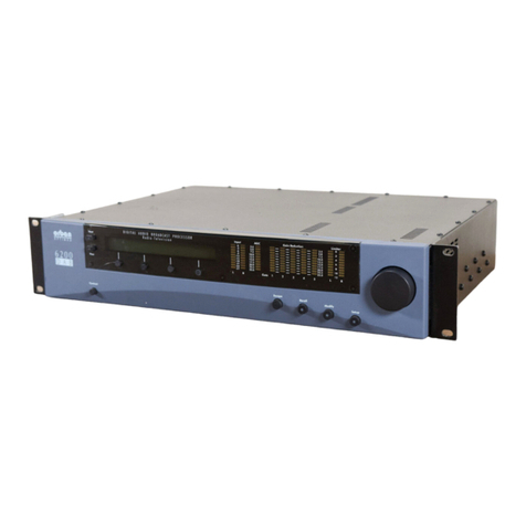
Orban OPTIMOD 5950 User manual

OPERATING MANUAL
OPTIMOD
5950
FM/HD/DAB+ Digital Audio Processor

O P T I M O D - 5 9 5 0 D I G I T A L A U D I O P R O C E S S O R
IMPORTANT NOTE: Refer to the unit for your Model and Serial number.
Model Number:
OPTIMOD 5950
Description:
M/HD/DAB+ Digital Audio Processor OPTIMOD 5950, Stereo Encoder, Digital I/O, Digital MPX I/O, Protection
Structure, Two-Band Structure, Multi-Band Structure, HD Radio™ / Digital Radio/Netcast Processing, Digital
Composite Output, Dante AES67-Compliant Audio-Over-IP, µMPX streaming, Dual-Redundant Power Supply 90 V
to 240V (automatically selected), switchable to 50µs or 75µs.
CAUTION: TO REDUCE THE RISK OF ELECTRICAL SHOCK, DO NOT REMOVE COVER (OR BACK). NO
USER SERVICEABLE PARTS INSIDE. REFER SERVICING TO QUALIFIED SERVICE PERSONNEL.
WARNING: TO REDUCE THE RISK OF FIRE OR ELECTRICAL SHOCK,
DO NOT EXPOSE THIS APPLIANCE TO RAIN OR MOISTURE.
T
his symbol, wherever it appears,
alerts you t
o the presence of
uninsulated dangerous voltage
inside the enclosure
voltage that
may be sufficient to constitute a
risk of shock.
This symbol, wherever it appears, alerts
you to important operating and
maintenance instructions in the
accompanying literature. Read the manual.

O P T I M O D - 5 9 5 0 D I G I T A L A U D I O P R O C E S S O R
In accordance to the WEEE (waste electrical and electronic equipment)
directive of the European Parliament, this product must not be
discarded into the municipal waste stream in any of the Member States.
This product may be sent back to your Orban dealer at end of life where
it will be reused or recycled at no cost to you.
If this product is discarded into an approved municipal WEEE collection
site or turned over to an approved WEEE recycler at end of life, your
Orban dealer must be notified and supplied with model, serial number
and the name and location of site/facility.
Please contact your Orban dealer for further assistance.
www.orban.com
TO PREVENT ELECTRICAL SHOCK, DO NOT REMOVE COVER
NO USER SERVICABLE PARTS INSIDE.
REFER SERVICING TO QUALIFIED SERVICE PRESEONNEL.
PROTECT AGHAINST HUMIDITY
© Copyright 2024 Orban Labs Inc.
Orban® and OPTIMOD® are trademarks of Orban Labs Inc..
Published January 2024.
This manual © copyright Orban Labs Inc. This manual may be freely printed out and distributed if this copyright
notice is not removed.

O P T I M O D - 5 9 5 0 D I G I T A L A U D I O P R O C E S S O R

O P T I M O D - 5 9 5 0 D I G I T A L A U D I O P R O C E S S O R
IMPORTANT SAFETY INSTRUCTIONS
All the safety and operating instructions should be read before the appliance is operated.
5HWDLQ,QVWUXFWLRQVThe safety and operation instructions should be retained for future reference.
+HHG:DUQLQJVAll warnings on the appliance and in the operating instructions should be adhered to.
)ROORZ,QVWUXFWLRQVAll operation and user instructions should be followed.
:DWHU DQG 0RLVWXUH
The appliance should not be used near water (e.g., near a bathtub, washbowl, kitchen sink, laundry tub, in a wet
basement, or near a swimming pool, etc.).
9HQWLODWLRQThe appliance should be situated so that its location or position does not interfere with its proper ventilation. For example
, the
appliance should not be situated on a bed, sofa, rug, or similar surface that may block the ventilation openings; or, placed in a built-
in installation, such
as a bookcase or cabinet that may impede the flow of air through the ventilation openings.
+HDWThe appliance should be situated away from heat sources such as radiators, h
eat registers, stoves, or other appliances (including amplifiers)
that produce heat.
3RZHU6RXUFHV
The appliance should be connected to a power supply only of the type described in the operating instructions or as marked on
the appliance.
*URXQGLQJRU3RODUL]DWLRQPrecautions should be taken so that the grounding or polarization means of an appliance is not defeated.
3RZHU-&RUG3URWHFWLRQPower-
supply cords should be routed so that they are not likely to be walked on or pinched by items placed upon or
against them, paying particular attention to cords at plugs, convenience receptacles, and the point where they exit from the appliance.
&OHDQLQJThe appliance should be cleaned only as recommended by the manufacturer.
1RQ-8VH3HULRGVThe power cord of the appliance should be unplugged from the outlet when left unused for a long period of time.
2EMHFWDQG/LTXLG(QWU\Care should be taken so that objects do not fall and liquids are not spilled into the enclosure through openings.
'DPDJH5HTXLULQJ6HUYLFH
The appliance should be serviced by qualified service personnel when: The power supply cord or the plug has
been damaged; or Objects have fallen, or liquid has been spilled into the appliance; or The appliance has been exposed to rai
n; or The appliance
does not appear to operate normally or exhibits a marked change in performance; or The appliance has been dropped, or the enclosure damaged.
6HUYLFLQJThe user should not attempt to service the appliance beyond that described in the operating instructions
. All other servicing should be
referred to qualified service personnel.
7KH$SSOLDQFHVKRXOGEHXVHGRQO\ZLWKDFDUWRUVWDQGWKDWLVUHFRPPHQGHGE\WKHPDQXIDFWXUHU
Safety Instructions (European)
Notice For U.K. Customers If Your Unit Is Equipped With A Power Cord.
WARNING: THIS APPLIANCE MUST BE EARTHED.
The cores in the mains lead are coloured in accordance with the following code:
GREEN and YELLOW - Earth BLUE - Neutral BROWN - Live
As colours of the cores in the mains lead of this appliance may not correspond with the coloured markings identifying the ter
minals in your plug,
proceed as follows:
The core which is coloured green and yellow must be connected to the terminal in the plug
marked with the letter E, or with the earth symbol, or
coloured green, or green and yellow.
The core which is coloured blue must be connected to the terminal marked N or coloured black.
The core which is coloured brown must be connected to the terminal marked L or coloured red.
The power cord is terminated in a CEE7/7 plug (Continental Europe). The green/yellow wire is connected directly to the unit's
chassis. If you need to
change the plug and if you are qualified to do so, refer to the table below.
WARNING: If the ground is defeated, certain fault conditions in the unit or in the system to which it is connected can result in
full line voltage between
chassis and earth ground. Severe injury or death can then result if the chassis and earth ground are touched simultaneously.
Conductor
WIRE COLOR
Normal
Alt
L
LIVE
BROWN
BLACK
N
NEUTRAL
BLUE
WHITE
E
EARTH GND
GREEN-YELLOW
GREEN
AC Power Cord Color Coding

O P T I M O D - 5 9 5 0 D I G I T A L A U D I O P R O C E S S O R
PLEASE READ BEFORE PROCEEDING!
Manual
The Operating Manual contains instructions to verify the proper operation of this unit and initialization of certain options. You will find these
operations are most conveniently performed on the bench before you install the unit in the rack. Please review the Manual, especially the
installation section, before unpacking the unit. Trial Period Precautions If your unit has been provided on a trial basis: You should observe the
following precautions to avoid reconditioning charges in case you later wish to return the unit to your dealer.
1) Note the packing technique and save all packing materials. It is not wise to ship in other than the factory carton. (Replacements cost
$50.00).
2) Avoid scratching the paint or plating. Set the unit on soft, clean surfaces.
3) Do not cut the grounding pin from the line cord.
4) Use care and proper tools in removing and tightening screws to avoid burring the heads.
5) Use the nylon-washered rack screws supplied, if possible, to avoid damaging the panel. Support the unit when tightening the screws so
that the threads do not scrape the paint inside the slotted holes.
Packing
When you pack the unit for shipping:
1) Tighten all screws on any barrier strip(s) so the screws do not fall out from vibration.
2) Wrap the unit in its original plastic bag to avoid abrading the paint.
3) Seal the inner and outer cartons with tape. If you are returning the unit permanently (for credit), be sure to enclose:
xThe Manual(s)
xThe Registration / Warranty Card
xThe Line Cord
xAll Miscellaneous Hardware (including the Rack Screws and Keys)
xThe Extender Card (if applicable)
xThe Monitor Rolloff Filter(s) (OPTIMOD-AM only)
xThe COAX Connecting Cable (THE OPTIMOD-5950 and OPTIMOD-TV only) Your dealer may charge you for any missing items. If you
are returning a unit for repair, do not enclose any of the above items. Further advice on proper packing and shipping is included in
the Manual (see Table of Contents).
Trouble
If you have problems with installation or operation:
(1) Check everything you have done so far against the instructions in the Manual. The information contained therein is based on our years of
experience with OPTIMOD and broadcast stations.
(2) Check the other sections of the Manual (consult the Table of Contents and Index) to see if there might be some suggestions regarding your
problem.

O P T I M O D - 5 9 5 0 D I G I T A L A U D I O P R O C E S S O R
(3) After reading the section on Factory Assistance, you may call Orban Customer Service for advice during normal business hours. The number
is +1 856.719.9900.
WARNING
This equipment generates, uses, and can radiate radio-frequency energy. If it is not installed
and used as directed by this manual, it may cause interference to radio communication. This
equipment complies with the limits for a Class A computing device, as specified by FCC
Rules, Part 15, subject J, which are designed to provide reasonable protection against such
interference when this type of equipment is operated in a commercial environment. Operation
of this equipment in a residential area is likely to cause interference. If it does, the user will be
UHTXLUHGWRHOLPLQDWHWKHLQWHUIHUHQFHDWWKHXVHU¶VH[SHQVH
WARNING
This digital apparatus does not exceed the Class A limits for radio noise emissions from
digital apparatus set out in the radio Interference Regulations of the Canadian Department of
Communications.
(Le present appareil numerique Q¶HPHW SDV GH EUXLWV UDGLR
electriques
depassant les limites applicables aux appareils numeriques [de las class A] prescrites dans le
Reglement sur le brouillage radioelectrique edicte par le ministere des Communications du
Canada.)
IMPORTANT
Perform the installation under static control conditions. Simply walking across a rug can
generate a static charge of 20,000 volts. This is the spark or shock you may have felt when
touching a doorknob or some other conductive surface. A much smaller static discharge is
likely to destroy one or more of the CMOS semiconductors employed in OPTIMOD
-
FM. Static
damage will not be covered under warranty.
There are many common sources of static. Most involve some type of friction between two
dissimilar materials. Some examples are combing your hair, sliding across a seat cover or
rolling a cart across the floor. Since the threshold of human perception for a static discharge
is 3000 volts, you will not even notice many damaging discharges.
Basic damage prevention consists of minimizing generation, discharging any accumulated
static charge on your body or workstation, and preventing that discharge from being sent to or
through an electronic component. You should use a static grounding strap (grounded through
a protective resistor) and a static safe workbench with a conductive surface. This will prevent
any buildup of damaging static.
All firmware and software © Orban. Orban and OPTIMOD are registered trademarks.
All trademarks are property of their respective companies.
This manual was published January 2024. © Copyright Orban.
This document may be freely printed and distributed by Orban’s customers, but its text may not be incorporated into derivative works.
Orban Labs Inc., 7209 Browning Road, Pennsauken NJ 08110 USA
Phone: +1 856.719.9900
E-Mail: support@orban.com
Site: www.orban.com

O P T I M O D - 5 9 5 0 D I G I T A L A U D I O P R O C E S S O R
Table of Contents
Section 1: Introduction....................................................................................................................1-1
Input/output Configuration....................................................................................................................................... 1-2
Digital AES3 Left/Right Input/Outputs....................................................................................................................... 1-2
Analog Left/Right Input/Output ................................................................................................................................ 1-3
Stereo Baseband Composite Output ......................................................................................................................... 1-3
Digital Composite Output .......................................................................................................................................... 1-3
Subcarriers................................................................................................................................................................. 1-3
Digitized Subcarrier Inputs ........................................................................................................................................ 1-4
Wordclock/10 MHz Sync Reference Input................................................................................................................. 1-4
Remote Control Interface .......................................................................................................................................... 1-4
Computer Interface ................................................................................................................................................... 1-4
Warranty, User Feedback .......................................................................................................................................... 1-5
Section 2: Installation......................................................................................................................2-1
Unboxing the 5950 .................................................................................................................................................... 2-1
Grounding.................................................................................................................................................................. 2-1
Surge Protection ........................................................................................................................................................ 2-2
UPS/Power Conditioning ........................................................................................................................................... 2-2
Where to locate the 5950.......................................................................................................................................... 2-2
Studio-Transmitter Link ............................................................................................................................................. 2-4
STL and Exciter Overshoot ......................................................................................................................................... 2-6
Monitoring on Loudspeakers and Headphones ........................................................................................................ 2-7
PC Control .................................................................................................................................................................. 2-9
Racking the 5950 ....................................................................................................................................................... 2-9
Cable .......................................................................................................................................................................... 2-9
Analog Audio Input .................................................................................................................................................... 2-9
Analog Audio Output ............................................................................................................................................... 2-10
AES3 Digital Input/Output ....................................................................................................................................... 2-10
Dante AES67 ............................................................................................................................................................ 2-11
Dante Firmware Updates......................................................................................................................................... 2-17
Composite Output and Subcarrier Input ................................................................................................................. 2-18
DMPX ....................................................................................................................................................................... 2-20

O P T I M O D - 5 9 5 0 D I G I T A L A U D I O P R O C E S S O R
µMPX Composite over IP ......................................................................................................................................... 2-20
Wordclock/10 MHz Sync Reference ........................................................................................................................ 2-21
Audio Grounding ..................................................................................................................................................... 2-21
Audio Circuit Grounds ............................................................................................................................................. 2-21
Optically Isolated Remote Control Connections...................................................................................................... 2-22
The 5950 Front Panel............................................................................................................................................... 2-24
Section 3: Operation .......................................................................................................................3-1
Introduction to Processing ........................................................................................................................................ 3-1
Fundamental Requirements: High-Quality Source Material and Accurate Monitoring ............................................ 3-3
About the 5950’s Signal Processing Features ............................................................................................................ 3-4
Customizing the 5950’s Sound ................................................................................................................................ 3-13
Factory Programming Presets ................................................................................................................................. 3-15
Adjusting and using the browser based PC Remote................................................................................................ 3-19
SETTING INPUT LEVELS ............................................................................................................................................ 3-19
HEADPHONE ............................................................................................................................................................ 3-20
Digital OUTPUT 1 (and 2) ......................................................................................................................................... 3-21
STEREO ENCODER .................................................................................................................................................... 3-23
RDS and RBDS .......................................................................................................................................................... 3-29
UTILITY ..................................................................................................................................................................... 3-40
LESS-MORE: .................................................................................................................... Error! Bookmark not defined.
STEREO ENHANCER:................................................................................................................................................. 3-45
AGC (Automatic Gain Control)................................................................................................................................. 3-46
EQUALIZER (EQ) ....................................................................................................................................................... 3-48
MULTIBAND ............................................................................................................................................................. 3-50
COMPRESSORS ........................................................................................................................................................ 3-53
SPEECH MODE ......................................................................................................................................................... 3-54
BANDMIX ................................................................................................................................................................. 3-55
MX PROCESSING ............................................................................................................. Error! Bookmark not defined.
FINAL CLIPPING............................................................................................................... Error! Bookmark not defined.
HD LIMITING ...................................................................................................................................……………………….3-65
RATINGS ENCODER LOOP……………………………………………………………………………………..3-70
Section 4: Maintenance...................................................................................................................4-1
Routine Maintenance ................................................................................................................................................ 4-1
Section 5: Troubleshooting..............................................................................................................5-1


O P T I M O D - 5 9 5 0 D I G I T A L A U D I O P R O C E S S O R
Problems and Potential Solutions.............................................................................................................................. 5-1
Section 6: Technical Data ................................................................................................................6-1
Jumper settings ......................................................................................................................................................... 6-1
Board Layout………………………………………………………………………………………………………6-2
Using Lossy Data Reduction in the Studio ................................................................................................................. 6-3
About Transmission Levels and Metering ................................................................................................................. 6-3
Line Up Facilities ........................................................................................................................................................ 6-5
Section 7: Specifications (Preliminary) .............................................................................................7-1


Orban 5950 Technical Manual Introduction 1-1
Section 1: Introduction
The OPTIMOD 5950 is a 1 RU (rack unit) broadcast audio processor designed for use with analog FM broadcasts as
well as digital broadcasts or streaming. It has a consistent 2 band AGC (Automatic Gain Control) followed by a 5
band processor and state of the art peak control. A separate peak control system in employed for those using the
processing for streaming or codec based processing such as HD or DAB+.
The OPTIMOD 5950 is a result of multiple generations of broadcast audio processing experience combined with
the latest technology to bring the end user a powerful tool for polishing their on air product. Take a little time now
to familiarize yourself with the OPTIMOD 5950. A small investment of your time now will yield large dividends in
audio quality.
Features of the OPTIMOD 5950 include:
xSix Processing structures to meet all format requirements from Classical to Contemporary and everything in
between.
xAdvanced, intelligent and consistent 2 band AGC with windowing, dual mode leveling and bass/master
controls to eliminate pumping.
xA 5 band dynamics processor for unparalleled consistency with both music and voice whether sourced locally
or from a network or syndicated program.
xOPTIMOD’s exclusive MX peak control technology for transient punch and airy highs.
xAn RDS/RBDS on-board encoder that supports dynamic PS scrolling and IP access.
xA full complement of factory tuned presets by professionals with the most experience in the industry. All
factory presets can be adjusted using Orban’s unique “Less/More” control which is an industry standard as a
guide to dial in a unique signature sound. Of course, more intrigate controls are also available to experienced
users for fine tuning the sound of any preset.
xAES67/SMPTE ST-2110 - Two redundant network interfaces are available for Audio-Over-IP connections
supporting AES67, RAVENNA™ and SMPTE ST-2110. AES67 provides both DANTE and Livewire+ ™
compatibility.
xThe 5950 can be controlled and configured via any HTML5 web browser. It also supports the SNMP v2 and the
Ember+ protocols.
xThe HTML5 web browser user interface offers a complete tool set to monitor and measure your signal,
including an oscilloscope and FFT displays.
xTwo internal and selectable Neilsen and Kantar watermarking encoder are available, allowing the FM and
HD/DAB+ processing to be independently watermarked.

1-2Introduction
xThe FM and HD/DAB+ processed signals can be monitored remotely via IP, allowing for processing
adjustments where a clean over-the-air signal isn’t available.
xOptional µMPX (micro MPX) allows transmission of DMPX over IP.
xHigh resolution front panel touch screen for ease of navigation.
Input/output Configuration
THE OPTIMOD-5950 will simultaneously accommodate:
xDigital AES3 left/right inputs.
xTwo Digital AES3 outputs, both of which can be switched independently to carry the following signals: FM
analog processed without diversity delay, FM analog processed with diversity delay, digital radio processed
without delay, digital radio processed with delay, or low delay monitor.
xDigital AES11 sync reference input.
xAnalog left/right inputs.
xAnalog left/right outputs, which can be switched independently to carry the following signals: FM analog
processed without diversity delay, FM analog processed with diversity delay, digital radio processed without
delay, digital radio processed with delay, or low delay monitor.
xAnalog and AES3 composite stereo outputs.
xSubcarrier (SCA and RDS/RBDS) input.
xDante dual-redundant audio-over-IP left/right inputs and outputs, 44.1 or 48 kHz.
Digital AES3 Left/Right Input/Outputs
The digital input and outputs conform to the professional AES3 standard. They all have sample rate converters to
allow operation at 32 kHz, 44.1 kHz, 48 kHz, 88.2 kHz, and 96 kHz sample frequency. For best peak control, operate
at 44.1 kHz or higher.
The left/right digital input is on one XLR-type female connector on the rear panel; the left/right digital outputs are
on two XLR-type male connectors on the rear panel. THE OPTIMOD-5950 simultaneously accommodates digital
and analog inputs and outputs.
You can switch any of the 5950’s outputs between the analog-channel processing, a low-delay monitor signal, and
the HD-channel processing. You select whether THE OPTIMOD-5950 uses the digital or analog input on the
Input/output screen, by PC remote control, or by GPI (General Purpose Interface) optically-isolated remote
control.

Orban 5950 Technical Manual Introduction 1-3
Both analog and digital outputs are active continuously. Level control of the AES3 input is via software control
through the INPUT/OUTPUT screens. In addition, an AES11 sync input can accommodate house sync. It will lock the
5950’s two AES3 outputs to this sync even if the digital input is asynchronous to house sync. In Ratings Encoder
Loop-Through mode, AES3 output #2 drives the ratings encoder and the OPTIMOD’s Sync Input is repurposed to
receive the output of the ratings encoder. When not being used to receive the output of a ratings encoder, the
sync input can be used to receive audio as a silence-sense fallback source.
Analog Left/Right Input/Output
The left and right analog inputs are on XLR-type female connectors on the rear panel. Input impedance is greater
than 10k ; balanced and floating. Inputs can accommodate up to +27 dBu (0 dBu = 0.775Vrms). The left and right
analog outputs are on XLR-type male connectors on the rear panel. Output impedance is 50:; balanced and
floating. They can drive 600:or higher impedances, balanced or unbalanced. The peak output level is adjustable
from –6 dBu to +24 dBu.
Level control of the analog inputs and outputs is a accomplished via software control through System Setup.
Stereo Baseband Composite Output
The stereo encoder has two unbalanced analog baseband outputs on two BNC connectors on the rear panel. Each
output can be strapped for 0 or 75:source impedance and can drive up to 8V peak-to-peak into 75:in parallel
with up to 0.047PF (100ft/30m of RG-59/U cable) before any significant audible performance degradation occurs
(see the footnote on page 1-16 and refer to Figure 2-3: Separation vs. load capacitance on page 2-10). Independent
level control of each output is via software in the INPUT/OUTPUT > COMPOSITE screen.
Digital Composite Output
The 5950 provides an AES3 digital composite output at 192 kHz sample rate. Its output level is set in the
Input/Output 5 screen titled Composite 2. At the PC remote, it is located in the I/O SETUP SCREEN with the tab
DIGITAL ENCODER. This output appears on a male XLR-type connector on the rear panel. This output is fully
compatible with and interoperable with the de-facto industry standard digital connection being implemented by
transmitter manufacturers and others.
Subcarriers
The stereo encoder has two unbalanced 600:subcarrier (SCA) inputs with rear-panel BNC connectors to accept
any subcarrier at or above 23 kHz. The subcarriers are mixed into each composite output and their level is not
affected by the composite level control for that output.
The 5950 does not digitize subcarriers appearing at these two inputs; the mixing occurs after D/A conversion and is
analog.

1-4Introduction
Subcarrier inputs sum into the composite baseband outputs before the digitally controlled composite attenuators.
The sensitivity of the both SCA inputs are variable from 220 mV p-p to >10 V p-p to produce 10% injection. Internal
PC-board-mounted trim pots determine the sensitivity.
The correct peak level of the stereo program applied to the stereo encoder sometimes depends on the number of
subcarriers in use. Some regulatory authorities require the total baseband peak modulation to be maintained
within specified limits. Thus, the level of the stereo main and subchannel must be reduced when a subcarrier is
turned on. The 5950’s remote control feature allows you to reduce the stereo main and subchannel level by
connecting an on/off signal from your subcarrier generator. You define the amount of reduction (in units of
percent modulation) on the Input/output screen. See page 2-62 for information on programming the remote
control. A jumper on the circuit board can reconfigure the SCA 2 input to provide the stereo pilot tone only, which
can provide a pilot reference for an RDS subcarrier generator.
Digitized Subcarrier Inputs
Two additional subcarrier inputs are provided on the rear panel. These are digitized and are summed only into the
digital composite output. Their mix level is set in the Input/Output 5 screen titled Composite 2. At the PC remote,
they are located in the I/O SETUP SCREEN with the tab DIGITAL ENCODER. If you need to use both the digital and
analog composite outputs, you must split the outputs of your SCA generators with Y cables so that each generator
output drives one digitized SCA input and one non-digitized SCA input.
Wordclock/10 MHz Sync Reference Input
The sync reference input (labeled REF IN) appears on a female BNC jack on the rear panel. It is available only on
MPX hardware. It accepts a 1x 5V p-p squarewave wordclock signal at 32, 44.1, 48, 88.2, or 96kHz, or a 10MHz
sinewave or squarewave signal, 0.5 to 5V peak. 10MHz is a common output frequency produced by GPS and
rubidium frequency standards. You can configure the 5950 to lock its 19kHz pilot tone and output sample
frequency to this input. When a valid reference signal is applied to this input, it locks the OPTIMOD’s Internal DSP
clock to this input, so if a given AES3 L/R output’s sync source is set to INTERNAL, the sample frequency at that
output will be locked to this reference signal.
Do not apply an AES3 signal to this input.
Remote Control Interface
The Remote Control Interface is a set of eight optically isolated inputs on a DB-25 connector that can be activated
by 5-12V DC. They can control various functions of the 5950.
Computer Interface
On the rear panel of the 5950 are serial ports and Ethernet ports. These computer interfaces support remote
control and metering, downloading software upgrades, and audio-over-IP connectivity. Each 5950 can be accessed
via a web browser using the IP address configured on the 5950.

Orban 5950 Technical Manual Introduction 1-5
x100 Mbps Ethernet Port for Remote Connectivity: This port will connect to any Ethernet-based network that
supports the TCP/IP protocol.
xDante Audio-Over-IP Ethernet Ports: These ports support dedicated Dante (100% AES 67-compatible) audio-
over-IP network connection, main and backup.
Warranty, User Feedback
User Feedback: We are very interested in your comments about this product. The 5950 was developed to make
adjustments to audio processing easy to make. We will carefully review your suggestions for improvements to
LIMITED WARRANTY: [Valid only for products purchased and used in the United States]
Orban warrants Orban products against defects in material or workmanship for a period of five years from the date
of original purchase for use, and agrees to repair or, at our option, replace any defective item without charge for
either parts or labor.
IMPORTANT: This warranty does not cover damage resulting from accident, misuse or abuse, lack of reasonable
care, the affixing of any attachment not provided with the product, loss of parts, or connecting the product to any
but the specified receptacles. This warranty is void unless service or repairs are performed by an authorized service
center. No responsibility is assumed for any special, incidental, or consequential damages. However, the limitation
of any right or remedy shall not be effective where such is prohibited or restricted by law.
Simply take or ship your Orban products prepaid to our service department. Be sure to include a copy of your sales
slip as proof of purchase date. We will not repair transit damage under the no-charge terms of this warranty.
Orban will pay return shipping.
No other warranty, written or oral, is authorized for Orban Products.
This warranty gives you specific legal rights and you may have other rights that vary from state to state. Some
states do not allow the exclusion of limitations of incidental or consequential damages or limitations on how long
an implied warranty lasts, so the above exclusions and limitations may not apply to you.
INTERNATIONAL WARRANTY: Orban warrants Orban products against evident defects in material and
workmanship for a period of five years from the date of original purchase for use. This warranty does not cover
damage resulting from misuse or abuse, or lack of reasonable care, or inadequate repairs performed by
unauthorized service centers.
Performance of repairs or replacements under this warranty is subject to submission of this Warranty/Registration
Card, completed and signed by the dealer on the day of purchase, and the sales slip. Shipment of the defective
item is for repair under this warranty will be at the customer’s own risk and expense. This warranty is valid for the
original purchaser only.


Orban 5950 Technical Manual Installation 2-1
Section 2: Installation
Unboxing the 5950
Once you have taken delivery of the 5950, you should open the box and check the unit for any damage from
shipping. Inside the box should be the following:
xOperating Manual
x2 Line Cords (domestic, European)
x4 Rack-mounting screws, 10-32 x ¾—with washers, #10
x1 Ethernet crossover cable
x1 OPTIMOD 5950 Audio Processor
If any of these items are damaged or missing, please contact your dealer or Orban as soon as possible.
Save all packing materials! If you should ever have to ship the 5950 (e.g., for servicing), it is best to ship it in the
original carton with its packing materials because both the carton and packing material have been carefully
designed to protect the unit.
Grounding
Establish a low impedance common ground in the facility and try to route all equipment grounds to that point,
using conductors with the largest possible surface area while keeping those leads as
short as possible. The 5950’s ground reference (its chassis) should be connected to
the station/transmitter site ground. Such a connection is especially important when
the 5950 is operated in a high RF environment because it helps minimize differential
voltages between the processor’s chassis and other pieces of equipment.

2-2Installation
Surge Protection
Always place surge protection circuits as close as possible to the 5950. AC power line surges should be handled in a
way that keeps instantaneous potential differences between the power line hot, neutral, AC grounding conductor,
the station ground and the processor chassis as low as possible. Likewise, measures should also be taken to keep
the instantaneous potential difference between the audio cable shields and the processor chassis as low as
possible (this applies to all audio equipment, not just the 5950), particularly when the equipment is located within
the electrically hostile environment of a station’s transmitter facility.
UPS/Power Conditioning
Choose the best power conditioning/UPS units that your budget will allow, focusing on the most important
features and options that you actually need. Some questions to ask while reviewing features are:
xHow does the unit handle AC power that is not exactly 60Hz, such as when the facility is on its backup
generator?
xIf the unit has onboard surge protection, what kind of surge capability does it have and where are those surges
directed to?
xIs the unit equipped with remote monitoring capability?
xDoes it have onboard monitoring and alarms to signal a problem such as batteries with low reserve?
Where to locate the 5950
The best location for THE OPTIMOD-5950 is as close as possible to the transmitter, so that its stereo encoder
output can be connected to the transmitter through a circuit path that introduces the least possible change in the
shape of THE OPTIMOD-5950’s carefully peak-limited composite waveform—a short length of coaxial cable. If this
is impossible, the next best arrangement is to feed the 5950’s AES3 digital output through an all-digital,
uncompressed path to the transmitter's exciter, although this will preclude using the 5950’s composite limiter.
Use the 5950’s left and right analog audio outputs in situations where the stereo encoder and exciter are under
the jurisdiction of an independent transmission authority and where the programming agency’s jurisdiction ends at
the interface between the audio facility and the link connecting the audio facility to the transmitter. (The link
might be telephone / post lines, analog microwave radio, or various types of digital paths.) This situation is not
ideal because artifacts that cannot be controlled by the audio processor can be introduced by the link to the
transmitter, by transmitter peak limiters, or by the external stereo encoder.
If the transmitter is not accessible: All audio processing must be done at the studio and you must tolerate any
damage that occurs later.
If you can obtain a broadband (0-75 kHz) phase-linear link to the transmitter and the transmitter authority will
accept the delivery of a baseband encoded signal, use the 5950’s internal stereo encoder at the studio location to

Orban 5950 Technical Manual Installation 2-3
feed the STL. Then feed the output of the STL receiver directly into the transmitter’s exciter with no intervening
processing.
If an uncompressed left/right digital link is available to the transmitter, this is also an excellent means of
transmission, although it will not pass the effects of the 5950’s composite processor (if you are using it). However,
if the digital link employs lossy compression, it will degrade peak control. To prevent overshoots caused by spectral
truncation in the link, set the 5950’s output sample rate to 44.1 kHz or higher.
If only an audio link is available, use the 5950’s left and right audio outputs and feed the audio, without pre-
emphasis, directly into the link. If possible, request that any transmitter protection limiters be adjusted for
minimum possible action—THE OPTIMOD-5950 does most of that work. Transmitter protection limiters should
respond only to signals caused by faults or by spurious peaks introduced by imperfections in the link. To ensure
maximum quality, all equipment in the signal path after the studio should be carefully aligned and qualified to
meet the appropriate standards for bandwidth, distortion, group delay and gain stability and such equipment
should be re-qualified at reasonable intervals.
If the transmitter is accessible: You can achieve the most accurate control of modulation peaks by locating THE
OPTIMOD-5950 at the transmitter site and then using its stereo encoder to drive the transmitter. You can usually
also obtain good results by locating THE OPTIMOD-5950 at the studio and connecting the baseband output of its
stereo encoder to the transmitter through a composite baseband STL.
However, many analog composite baseband STLs do not control peaks perfectly and locating THE OPTIMOD-5950
at the transmitter site (where it can control peaks just prior to the transmitter’s RF exciter) is thus likely to
maximize loudness. The ideal link is an uncompressed digital composite STL because these have virtually flawless
waveform fidelity and allow full use of the 5950’s composite limiter.
Because THE OPTIMOD-5950 controls peaks, it is irrelevant whether the audio link feeding THE OPTIMOD-5950’s
input terminals is phase-linear. However, the link should have low noise, the flattest possible frequency response
from 30-15,000Hz, and low nonlinear distortion.
We strongly recommend that you use the 5950’s internal stereo encoder to feed the output of the encoder
directly. You will achieve a louder sound on the air, with better control of peak modulation, than if you use current
external stereo encoders.
The shorter the baseband cable from THE OPTIMOD-5950 to exciter, the less likely that ground loops or other
noise problems will occur in the installation. If you require a long cable run, you can use a Jensen JT-123-BMCF
transformer1 to break any ground loops. This transformer will usually cure even the most stubborn hum or noise
caused by the composite connection between THE OPTIMOD-5950 and the exciter.
Table of contents
Other Orban Computer Hardware manuals

Orban
Orban OPTIMOD-FM 8600Si User manual

Orban
Orban OPTIMOD-FM 8100A/XT2 User manual

Orban
Orban OPTIMOD-FM 8100A/1 User manual

Orban
Orban OPTIMOD-FMR 8100A/1 User manual

Orban
Orban RET-044 Owner's manual

Orban
Orban OPTIMOD 6300 User manual

Orban
Orban OPTIMOD 5750 User manual

Orban
Orban OPTIMOD 8400 User manual

Orban
Orban OPTIMOD 8685 User manual

Orban
Orban OPTIMOD-FM 8500 Quick start guide

Orban
Orban OPTIMOD-FM 8700i User manual

Orban
Orban OPTIMOD-FM 8500 Quick start guide

Orban
Orban OPTIMOD 6200 User manual

Orban
Orban OPTIMOD-FM 5500 User manual

Orban
Orban OPTIMOD 6300 User manual

Orban
Orban OPTIMOD-FM 5700i User manual

Orban
Orban OPTIMOD-FM 5500 User manual

Orban
Orban RET-041 Owner's manual