foc.us CS-HD User manual

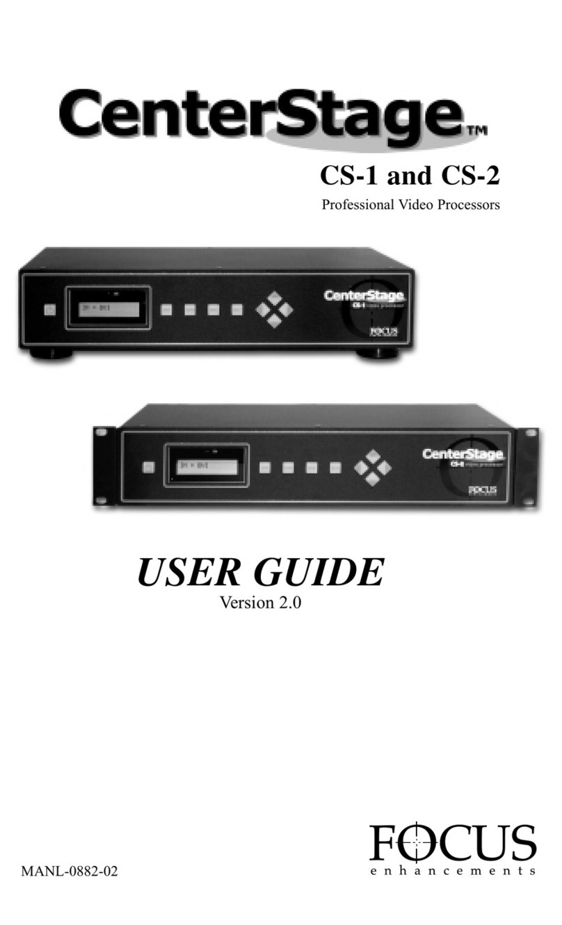
CS-HD
Professional Video Processor
USER GUIDE

CS-HD
Professional Video Processor
USER GUIDE
MANL-0900-01

CenterStage
PAGE 2
Please read through these operating instructions so you will know how to operate your model
properly. After you have finished reading the instructions, put them away in a safe place for
future reference.
WARNING: TO PREVENT FIRE OR
SHOCK HAZARD, DO NOT EXPOSE
THIS APPLIANCE TO RAIN OR
MOISTURE.
IMPORTANT NOTICE
(For U.S.Model)
The serial number for this equipment is located
on the bottom of the unit. Please write this serial
number on your enclosed warranty card and
keep it in a secure area. This is for your security.
CAUTION:
This product satisfies FCC regulations when
shielded cables and connectors are used to
connect the unit to other equipment. To prevent
electromagnetic interference with electric
appliances such as radios and televisions, use
shielded cables and connectors for connections.
NOTE:
This equipment has been tested and found
to comply with the limits for a Class B
digital device, pursuant to Part 15 of the
FCC Rules. These limits are designed to
provide reasonable protection against harmful
interference in a residential installation.
This equipment generates, uses, and can
radiate radio frequency energy and, if not
installed and used in accordance with the
instructions, may cause harmful interference
to radio communications. However, there is
no guarantee that interference will not
occur in a particular installation. If this
equipment does cause harmful interference
to radio or television reception,which can
be determined by turning the equipment off
and on, the user is encouraged to try to
correct the interference by one or more
of the following measures:
• Reorient or relocate the receiving
antenna.
• Increase the separation between the
equipment and receiver.
• Connect the equipment into an outlet
on a circuit different from that to
which the receiver is connected.
• Consult the dealer or an experienced
radio/TV technician for help.
INFORMATION TO USER
Alteration or modifications carried out
without appropriate authorization may
invalidate the user’s right to operate
the equipment.
CAUTION:
•Use of controls or adjustments or
performance of procedures other than
those specified herein may result in
hazardous radiation exposure.
•The use of optical instruments with
this product will increase eye hazard.
THE STANDBY/ON BUTTON IS
SECONDARY CONNECTED AND
THEREFORE DOES NOT SEPARATE
THE UNIT FROM MAINS POWER
IN STANDBY POSITION.
CAUTION: TO PREVENT ELECTRIC
SHOCK, DO NOT USE THIS (POLARIZED)
PLUG WITH AN EXTENSION CORD,
RECEPTACLE OR OTHER OUTLET UNLESS
THE BLADES CAN BE FULLY INSERTED
TO PREVENT BLADE EXPOSURE.
ATTENTION: POUR PREVENIR LES
CHOCS ELECTRIQUES NE PAS UTILISER
CETTE FICHE POLARISEE AVEC UN
PROLONGATEUR, UNE PRISE DE COURANT
OU UNE AUTRE SORTIE DE COURANT,
SAUF SI LES LAMES PEUVENT ETRE
INSEREES A FOND SANS EN LAISSER
AUCUNE PARTIE A DECOUVERT.

CenterStage
IMPORTANT
The lightning flash with arrowhead
symbol, within an equilateral triangle,
is intended to alert the user to the
presence of uninsulated “dangerous
voltage ”within the product’s
enclosure that may be of sufficient
magnitude to constitute a risk of
electric shock to persons.
CAUTION:
TO PREVENT THE RISK OF
ELECTRIC SHOCK, DO NOT
REMOVE COVER (OR BACK).
NO USER SERVICEABLE PARTS
INSIDE.REFER SERVICING TO
QUALIFIED SERVICE PERSONNEL.
The exclamation point within an
equilateral triangle is intended to alert
the user to the presence of important
operating and maintenance (servicing)
instructions in the literature accompanying
the appliance.
READ INSTRUCTIONS – All the safety and
operating instructions should be read before the
product is operated.
RETAIN INSTRUCTIONS –The safety and
operating instructions should be retained for
future reference.
HEED WARNINGS –All warnings on the product
and in the operating instructions should be
adhered to.
FOLLOW INSTRUCTIONS –All operating and use
instructions should be followed.
CLEANING –Unplug this product from the wall
outlet before cleaning. The product should be
cleaned only with a polishing cloth or a soft dry
cloth. Never clean with furniture wax, benzine,
insecticides or other volatile liquids since they
may corrode the cabinet.
ATTACHMENTS –Do not use attachments not
recommended by the product manufacturer as
they may cause hazards.
WATER AND MOISTURE –Do not use this
product near water –for example, near a bathtub,
wash bowl, kitchen sink, or laundry tub; in a wet
basement; or near a swimming pool; and the like.
ACCESSORIES –Do not place this product on an
unstable cart, stand, tripod, bracket or table. The
product may fall, causing serious injury to a child
or an adult, and serious damage to the product.
Use only with a cart, stand, tripod, bracket or
table recommended by the manufacturer, or sold
with the product. Any mounting of the product
should follow the manufacturer’s instructions, and
should use a mounting accessory recommended
by the manufacturer.
CART –A product and cart combination should be
moved with care. Quick stops, excessive force,
and uneven surfaces may cause the product and
cart combination to overturn.
VENTILATION –Slots and openings in the cabinet
are provided for ventilation and to ensure reliable
operation of the product and to protect it from
overheating, and these openings must not be
blocked or covered. The openings should never be
blocked by placing the product on a bed, sofa, rug,
or other similar surface. This product should not be
placed in a built-in installation such as a bookcase
or rack unless proper ventilation is provided or the
manufacturer’s instructions have been adhered to.
POWER SOURCES –This product should be
operated only form the type of power source
indicated on the marking label. If you are not sure of
the type of power supply to your home, consult
your dealer or local power company.
LOCATION –The appliance should be installed in
a stable location.
NON-USE PERIODS –The power cord of the
appliance should be unplugged from the outlet
when left unused for a long period of time.
GROUNDING OR POLARIZATION –
•If this product is equipped with a polarized
alternating current line plug ( a plug having one
blade wider than the other), it will fit into the
outlet only one way. This is a safety feature. If
you are unable to insert the plug fully into the
outlet, try reversing the plug. If the plug should
still fail to fit, contact your electrician to replace
your obsolete outlet. Do not defeat the safety
purpose of the polarized plug.
•If this product is equipped with a three-wire
grounding type plug, a plug having a third
(grounding) pin, it will only fit into a grounding
type power outlet. This is a safety feature. If you
are unable to insert the plug into the outlet,
contact your electrician to replace your obsolete
outlet. Do not defeat the safety purpose of the
grounding type plug.
POWER-CORD PROTECTION –Power supply cords
should be routed so that they are not likely to be
walked on or pinched by items placed upon or
against them, paying particular attention to cords at
plugs, convenience receptacles, and the point where
they exit the product.
OUTDOOR ANTENNA GROUNDING –If an outside
antenna or cable system is connected to the
product, be sure the antenna or cable system is
grounded so as to provide some protection against
voltage surges and built-up static charges. Article
810 of the National Electric Code, ANSI/NFPA 70,
provides information with regard to proper
grounding of the mast and supporting structure,
grounding of the lead-in wire to an antenna
discharge unit, size of grounding connectors,
location of antenna discharge unit, connection to
grounding electrodes, and requirements for the
grounding electrode. See Fig. A.
LIGHTNING –For added protection for this product
during a lightning storm, or when it is left unattended
and unused for long periods of time, unplug it from
the wall outlet and disconnect the antenna or cable
system. This will prevent damage to the product due
to lightning and power-line surges.
POWER LINES –An outside antenna system
should not be located in the vicinity of overhead
power lines or other electric light or power
circuits, or where it can fall into such power lines
or circuits. When installing an outside antenna
system, extreme care should be taken to keep
from touching such power lines or circuits as
contact with them might be fatal.
OVERLOADING –Do not overload wall outlets,
extension cords, or integral convenience
receptacles as this can result in a risk of fire or
electric shock.
OBJECT AND LIQUID ENTRY –Never push
objects of any kind into this product through
openings as they may touch dangerous voltage
points or short-out parts that could result in a fire
or electric shock. Never spill liquid of any kind on
the product.
SERVICING –Do not attempt to service this
product yourself as opening or removing covers
may expose you to dangerous voltage or other
hazards. Refer all servicing to qualified service
personnel.
DAMAGE REQUIRING SERVICE –Unplug this
product from the wall outlet and refer servicing to
qualified service personnel under the following
conditions:
•When the power-supply cord or plug is damaged.
•If liquid has been spilled, or objects have fallen
into the product.
•If the product has been exposed to rain or water.
•If the product does not operate normally by
following the operating instructions. Adjust
only those controls that are covered by the
operating instructions as an improper
adjustment of other controls may result in
damage and will often require extensive work
by a qualified technician to restore the product
to its normal operation.
•If the product has been dropped or damaged in
any way.
•When the product exhibits a distinct change in
performance –this indicates a need for service.
REPLACEMENT PARTS –When replacement parts
are required, be sure the service technician has
used replacement parts specified by the
manufacturer or have the same characteristics as
the original part. Unauthorized substitutions may
result in fire, electric shock or other hazards.
SAFETY CHECK –Upon completion of any service
or repairs to this product, ask the service
technician to perform safety checks to determine
that the product is in proper operating condition.
WALL OR CEILING MOUNT –The product should
not be mounted to a wall or ceiling.
HEAT –The product should be situated away from
heat sources such as radiators, heat, registers,
stoves or other products (including amplifiers)
that produce heat.
ELECTRIC
SERVICE
EQUIPMENT
GROUND
CLAMP
ANTENNA
LEAD IN WIRE
ANTENNA
DISCHARGE UNIT
(NEC SECTION 810-20)
GROUNDING CONDUCTORS
(NEC SECTION 810-21)
NEC — NATIONAL ELECTRICAL CODE
GROUND CLAMPS
POWER SERVICE GROUNDING
ELECTRODE SYSTEM
(NEC ART 250. PART H)
Fig A
CAUTION
RISK OF ELECTRIC SHOCK
DO NOT OPEN
IMPORTANT SAFETY INSTRUCTIONS

Table of Contents PAGE
Warning and Safety Information . . . . . . . . . . . . . . . . . . . . . . . . . . . . . . . . . . . . . . . . . . . . . . . .2
Statement of Compliance . . . . . . . . . . . . . . . . . . . . . . . . . . . . . . . . . . . . . . . . . . . . . . . . . . . . .5
Statement of Warranty . . . . . . . . . . . . . . . . . . . . . . . . . . . . . . . . . . . . . . . . . . . . . . . . . . . . . . . .6
Introduction &Setup 7
Introduction . . . . . . . . . . . . . . . . . . . . . . . . . . . . . . . . . . . . . . . . . . . . . . . . . . . . . . . . . . . . . . . .7
Unpacking &Inventory . . . . . . . . . . . . . . . . . . . . . . . . . . . . . . . . . . . . . . . . . . . . . . . . . . . . . . .7
Front Panel . . . . . . . . . . . . . . . . . . . . . . . . . . . . . . . . . . . . . . . . . . . . . . . . . . . . . . . . . . . . . . . .8
Rear Panel . . . . . . . . . . . . . . . . . . . . . . . . . . . . . . . . . . . . . . . . . . . . . . . . . . . . . . . . . . . . . . . . .9
Remote Control . . . . . . . . . . . . . . . . . . . . . . . . . . . . . . . . . . . . . . . . . . . . . . . . . . . . . . . . . . . .10
Typical Configuration . . . . . . . . . . . . . . . . . . . . . . . . . . . . . . . . . . . . . . . . . . . . . . . . . . . . . . .11
Setting Up CenterStage 12
Connecting Input Devices . . . . . . . . . . . . . . . . . . . . . . . . . . . . . . . . . . . . . . . . . . . . . . . . . . . .12
Connecting To Display Devices . . . . . . . . . . . . . . . . . . . . . . . . . . . . . . . . . . . . . . . . . . . . . . . .13
Powering Up CenterStage,Input and Output Devices . . . . . . . . . . . . . . . . . . . . . . . . . . . . . . . .13
Selecting An Input Source . . . . . . . . . . . . . . . . . . . . . . . . . . . . . . . . . . . . . . . . . . . . . . . . . . . .14
Selecting An Output Resolution . . . . . . . . . . . . . . . . . . . . . . . . . . . . . . . . . . . . . . . . . . . . . . . .15
The Main Men 16
Navigating the Main Menu . . . . . . . . . . . . . . . . . . . . . . . . . . . . . . . . . . . . . . . . . . . . . . . . . . .16
Picture Settings Menu . . . . . . . . . . . . . . . . . . . . . . . . . . . . . . . . . . . . . . . . . . . . . . . . . . . . . . .17
Output Selection Menu . . . . . . . . . . . . . . . . . . . . . . . . . . . . . . . . . . . . . . . . . . . . . . . . . . . . . .18
Input Selections Menu . . . . . . . . . . . . . . . . . . . . . . . . . . . . . . . . . . . . . . . . . . . . . . . . . . . . . .19
Miscellaneous Menu . . . . . . . . . . . . . . . . . . . . . . . . . . . . . . . . . . . . . . . . . . . . . . . . . . . . . . . .19
Technical Specifications 21
APPENDIX A: IR Remote Control Protocol 22
APPENDIX B: Input Aspect Ratio to Output Aspect Ratio Primer 26
Notes 27
CenterStage
PAGE 4

CenterStage
PAGE 5

CenterStage
PAGE 6
FOCUS Enhancements, Inc. warrants
this product against defects in materials
or workmanship as follows:
For a period of TWO years from the date
of purchase, FOCUS Enhancements, Inc.
will repair or replace the unit, at our option,
without charge for parts or labor. After the
period of TWO years, you must pay all
parts and labor charges.
The limited warranty is extended only to
the original purchaser and is valid only to
consumers in the United States and Canada.
It does not cover damage or failure caused
by or attributable to Acts of God, abuse,
misuse, improper or abnormal usage, faulty
installation, improper maintenance, lightning,
or other incidences of excessive voltage, or
any repairs or tampering by other than a
FOCUS Enhancements authorized repair
facility. It does not cover replacement
of batteries or other consumable parts,
transportation costs or damage in transit.
This warranty will become void if the serial
number or model number identification has
been wholly or partially removed or erased.
Repair or replacement under the terms of
this warranty do not extend the terms of this
warranty. This warranty can not be modified
by an agent of FOCUS Enhancements, Inc.
unless in written and signed by an officer
of FOCUS Enhancements, Inc.
Should this product prove defective in
workmanship or material, the consumer’s
sole remedies shall be such repair or
replacement provided by the terms of
this warranty. Under no circumstances shall
FOCUS Enhancements, Inc. be liable for
any loss or damage, direct, consequential, or
incidental, arising out of the use of or inability
to use this product. Some states do not allow
limitations on how long an implied warranty
lasts or the exclusions or limitations of
incidental or consequential damages, so the
above limitations or exclusions may not apply
to you. This warranty gives you specific legal
rights. You may also have other rights which
vary from state to state.
For customers outside the USA or Canada,
please contact your dealer or distributor for
repairs or technical support.
In the United States or Canada, to obtain
warranty service, call or write the FOCUS
Enhancements, Inc. Technical Support Line
for a Return Material Authorization (RMA)
number. Technical Support can be reached at:
Email: support@FOCUSinfo. com
Telephone: 408-370-9963. 8AM-5PM,
Monday to Friday (PST)
(Hint: Mondays tend to be the busiest)
Fax: 408-866-4859
Address: FOCUS Enhancements, Inc.
1370 Dell Ave.
Campbell, CA. 95008
Please mark the RMA number clearly on
the outside of the package. Include a copy
of your sales receipt, a brief description of the
symptoms, your name, address, phone number
and any special shipping instructions. Then
deliver or ship the product, postage and shipping
costs prepaid, to a FOCUS Enhancements
authorized repair facility. For the name of
the nearest repair facility, contact FOCUS
Enhancements, Inc. Technical Support.

INTRODUCTION & SETUP
Introduction
Thank you for purchasing the CenterStage CS-HD Video Processor from FOCUS Enhancements.
CenterStage offers exceptional image quality, flexibility, and the latest de-interlacing digital
video processing and scaling technology.
The purpose of this User Guide is to describe the various capabilities, specifications and other
information about your CenterStage unit. For additional information or technical support, please
contact your FOCUS Enhancements distributor or dealer. If you are in the US or Canada, you
can contact FOCUS Enhancements directly at:
Technical Support
Email: [email protected]
WWW: http://www.focusinfo.com/support/
Telephone: 408-370-9963. 8AM-5PM, Monday to Friday (PST)
(Hint: Mondays tend to be the busiest)
Fax: 408-866-4859
Unpacking & Inventory
Remove your CenterStage unit from its shipping container. You should have the following items
included with the unit:
•CenterStage unit
•User Guide
•IEC Power Cord
•VGA pass-thru cable (HD15M –HD15F)
•Infrared Remote Control and Batteries
•Warranty Card and Limited Warranty Statement
Please ensure all these items are included. Inspect the CenterStage unit for any signs of shipping
damage. It’s advised that you keep all shipping materials if the unit is to be moved or returned for
service at a later date.
CenterStage
PAGE 7

CenterStage
PAGE 8
FRONT PANEL
1. POWER
This button powers the CenterStage unit
ON and OFF. The On/Off power switch on
the rear panel of CenterStage must be in the
ON position for the front panel power switch
to work.
2. INFRARED REMOTE SENSOR
Sensor for CenterStage’s infrared remote
control unit.
3. AMBIENT LIGHT SENSOR
This sensor detects room ambient light and
changes the brightness of CenterStage’s LCD
and buttons. In dark areas, the CenterStage
LCD and buttons will be dimmer while in
bright areas, they will be brighter.
4. LCD DISPLAY
The 32-character LCD displays the current
CenterStage input source and output resolution
(ships with a protective cover film, simply
remove before using).
5. INPUT
Pressing this button cycles through the
available inputs on CenterStage. To execute,
press the SELECT button. If you do not press
the SELECT button, the input will revert to
the previous selection. The current input will
display on the top line of the LCD display.
6. OUTPUT
Pressing this button cycles through the
available output resolutions on CenterStage.
To execute, press the SELECT button. If you
do not press the SELECT button, the output
will revert to the previous selection. The current
output will display on the bottom line of the
LCD display.
7. MENU
Pressing this button brings up the CenterStage
Main Menu on the On Screen Display. It is
necessary to have a display device connected
to view this menu.
8. SELECT
This button is used for selecting various
options within the CenterStage On Screen
Display Menu. It is also used for executing
a new INPUT or OUTPUT selection.
9. NAVIGATION BUTTONS
This group of buttons allows for navigation
through the various CenterStage menu items.
1 2 3 4 5 6 7 8 9

CenterStage
PAGE 9
REAR PANEL
1. DVI OUT
DVI (Digital Visual Interface) digital
high resolution output.
2. DISPLAY OUT
HD-15F high
resolution output.
3. VGA/HDTV IN
HD-15M active buffered VGA or Analog
HDTV pass through.
4. PROGRESSIVE IN – Y, Pb, Pr
Progressive YPrPb input
5. INTERLACED IN –Y, Pb, Pr
Channel A & B
Interlaced YPrPb input
6. INTERLACED IN –C (COMPOSITE)
Channel A & B
Interlaced Composite input
7. INTERLACED IN –S (S-VIDEO)
Channel A & B
Interlaced S-Video input
8. SCREEN
Screen Trigger (12V, 3.5mm, 2-pin, Tip=+)
9. POWER SWITCH
10. FUSE
250V rating, 1.6A slow blow, 5mm x 20mm.
Replace with same fuse only.
11. IEC POWER CONNECTOR
AC Power Inlet. Use supplied IEC power cable
only. 100-240V AC, Auto Ranging, 50-60Hz
1 2 3 4 5 6 7 8 9 10 11

CenterStage
PAGE 10
REMOTE CONTROL 1. POWER
CenterStage ON/OFF Button.
2. ON SCREEN DISPLAY CONTROL
This bank of buttons features control for
the CenterStage On Screen Display (OSD).
Pressing MENU launches the OSD, EXIT
will exit the particular menu item or the OSD
itself, SELECT is used to choose various
options in the menus and the arrow keys are
used for navigation.
3. FILM/VIDEO SELECT
This bank of buttons is used for selecting
either FILM BIAS or STANDARD VIDEO
DSP settings for the output.
4. INPUT ASPECT RATIO
This bank of buttons allows selection of
the input aspect ratio. Choose from 16:9,
4:3 or LB (Letterbox, 4:3 or 16:9).
5. PICTURE SETTINGS
This bank of buttons allows for adjustment of
the output image. It will launch CenterStage’s
OSD to adjust either BRIGHTNESS,
CONTRAST or SHARPNESS.
6. INPUT SELECTION
This bank of buttons allows selection of
CenterStage input sources. Choose from
Composite Ch. A, Composite Ch. B, S-Video
Ch. A, S-Video Ch. B, YPrPb (Component)
Ch. A, YPrPb (Component) Ch. B, Progressive
(Component) and VGA Pass Thru. Upon
selection CenterStage will immediately
change to that selected input source. It is not
necessary to press SELECT once you have
chosen an input on the remote. DVI is not
used on the CS-HD model.
1
2
3
4
5
6

TYPICAL CONFIGURATION
CenterStage
PAGE 11

SETTING UP CENTERSTAGE
Once you have unpacked your CenterStage unit and have become familiar with the front and back
panel and remote features, install the CenterStage unit where it will be used. Study the TYPICAL
CONFIGURATION from the previous page and identify which input sources as well as which
output displays you intend to use with your CenterStage video processor. You may need to consult
your input and display device manuals for precise specifications. Make sure you have these
available before attempting to connect anything.
Connecting Input Devices
Once you have identified the input devices you intend to use, connect these devices to
CenterStage. It is possible to connect nine devices to CenterStage. Be aware that while devices
may have similar connectors, the output standard may differ from one unit to another. Consult
your input devices’specifications for more information. Your input choices are:
CenterStage CS-HD
Input Connector Standard Input Device Example
VGA HD-15M VESA or HDTV Computer, HDTV Analog
Progressive 3 x RCA YPrPb Progressive Output DVD Player
2 x Interlaced 3 x RCA YPrPb DVD Player
YPrPb
2 x Interlaced RCA Composite Set Top Box, Cable Box,
Composite Satellite
2 x Interlaced 4- pin mini DIN S-Video (Y/C) Set Top Box, Cable Box, S-Video
S-Video Satellite Receiver, DVD Player
CenterStage
PAGE 12

CONNECTING TO DISPLAY DEVICES
Once you have connected your desired input devices you can now connect your display device.
Be aware that while devices may have similar connectors, the output standard may differ from one
unit to another. While it is possible to connect two display devices to CenterStage, we recommend
that only one be connected at a time. This is due to the fact that output settings are global and settings
for one display may not match that of another. The two outputs available on CenterStage are:
CenterStage CS-HD
Output Connector Standard Output Device Example
DISPLAY OUT HD-15F Analog Projector, HD Monitor, Plasma Display,
Computer Monitor.
DVI OUT DVI-D DVI DVI enabled Plasma
Display, HD Monitor or Computer Monitor
Powering Up CenterStage, Input and Output Devices
Once you have connected all desired input devices and your display device, power up each of the
input devices followed by the display device. If you are unsure how to do this, consult your input
or display device instruction manual.
Once all your input devices and display are powered up, you can power up the CenterStage unit.
First check that you have connected the supplied IEC power cable and then turn on the Main
Power Switch on the rear of the unit (see page 9 for more details). Then you can either turn on
CenterStage by pressing the “POWER”button on the supplied remote control or by pressing the
(POWER) button on the front panel of the unit. The LCD display and buttons will light
up green.
If you have a video source connected to the “Composite Channel A”input on CenterStage, you
will see the following LCD display:
If no video source is connected to “Composite Channel A”on CenterStage, you will see the
following LCD display:
CenterStage
PAGE 13

SELECTING AN INPUT SOURCE
Once you have powered up your CenterStage unit and sources, it is possible to select the desired
input source. This is done by pressing CenterStage’s (INPUT) button. By pressing this
button, CenterStage will cycle through the available inputs. To execute a selection, press the
(SELECT) button. If SELECT is not pressed, the CenterStage will revert to the previous
selection. It is also possible to select an input directly using the CenterStage remote control unit
(It is not necessary to press SELECT on the remote). These will display on the top line
of the CenterStage LCD display.
Available inputs for CenterStage CS-HD are:
INPUT NAME INPUT
COMPOSITE A Composite Channel A
COMPOSITE B Composite Channel B
S-VIDEO A S-Video Channel A
S-VIDEO B S-Video Channel B
YPrPb A YUV (Y,Pr,Pb) Channel A
YPrPb B YUV (Y,Pr,Pb) Channel B
PROG. YPrPb Progressive Component (Y,Pr,Pb)
VGA PASS VGA (Computer) Active Pass-Thru
If a video input is detected on the selected input, CenterStage will display the output resolution
on the bottom line of the LCD display. If no video input is detected, CenterStage will display
a question mark (“? ”) next to the input name on the LCD display.
CenterStage
PAGE 14

SELECTING AN OUTPUT RESOLUTION
To select an output display resolution, first consult the User Guide or specification of your
Display device.
Press CenterStage’s (OUTPUT) button
to cycle through the available output resolutions. To execute a selection, press the
(SELECT) button. If SELECT is not pressed, the CenterStage will revert to the previous
selection. These will display on the bottom line of the CenterStage LCD display.
The factory set of available output resolutions for CenterStage CS-HD are:
The CenterStage-HD will support frame rate conversion as part of it’s internal controller, and
therefore, the output frequency is not limited to 50Hz output when inputting a PAL 50Hz signal.
The CenterStage-HD will support the following output resolutions:
720x480
720x576
960x540p
720p
1080i
1080p
720x480_DVI
720x576_DVI
720p _DVI
1080i _DVI
1280x1024_DVI
720x480_RGB
720x576_RGB
720p _RGB
1080i _RGB
1280x1024_RGB
Your display may work with several resolutions. It also may require some adjustment on the
display itself in order to size the picture etc. It is recommended that you adjust your display
device first before adjusting/fine tuning with CenterStage.
CenterStage
PAGE 15

THE MAIN MENU
It is possible to change picture settings, output selections, picture size and position, input selections
as well as other settings using the CenterStage Main Menu. The Main Menu appears on the
CenterStage On Screen Display (OSD). To activate the Main Menu, you must have CenterStage
connected to an appropriate display device and it is also a good idea to use a setup DVD such as
Video Essentials - Optimizing Your Audio/Video System or the AVIA Guide to Home Theater. These
will assist greatly in achieving a good image.
Navigating the Main Menu
To bring up the CenterStage OSD, press the (MENU) button. It is also possible
to launch the Main Menu by pressing the MENU button on the remote control unit.
The following should appear on your display device:
To navigate through the menu, press the (UP) and (DOWN) buttons on the
CenterStage front panel (you can also use the remote control). To select a particular menu, press
the (SELECT) button. The selected menu will appear on the On Screen Display.
CenterStage
PAGE 16
MAIN MENU
Picture Settings
Output Selections
Input Selections
Miscellaneous

Picture Settings Menu
In the PICTURE SETTINGS menu, it is possible to change input source:
BRIGHTNESS: Values are adjustable between –50 and +50.
CONTRAST: Values are adjustable between –50 and +50.
SHARPNESS: Value is adjustable between –50 and +50.
SATURATION: Also known as Color Saturation. Values are adjustable between –50 and +50.
HUE: Value is adjustable between –50 and +50.
RESET: Selecting this option will return all values in PICTURE SETTINGS to the factory
default state (all values reset to 0).
MAIN MENU: Exits to the Main Menu.
In all cases above, the default value will produce internal digital values in accordance with
ITU656 and an analog RGB HI RES out with a full-scale range of 0. 0 to 0. 7V when a 100%
amplitude and a 100% saturation color bar test pattern is applied to the CenterStage composite
input.
CenterStage
PAGE 17
BRIGHTNESS: 0
____________|______________
CONTRAST: 0
____________|______________
SHARPNESS: 0
____________|______________
SATURATION: 0
____________|______________
HUE: 0
____________|______________
[RESET]:
[MAIN MENU]:

Output Selection Menu
In the OUTPUT SELECTIONS menu, it is possible to change variables relating to the output of
CenterStage. The OUTPUT SELECTIONS menu items are:
RESOLUTION: Identifies the current output resolution.
OUTPUT ASPECT: Allows selection of either 4:3, 4:3 AL (Anamorphic lens) or 16:9 output
aspect ratio for the selected resolution.
OUTPUT V POSN: Allows you to adjust the vertical position of the output image (use the
(LEFT) button for up and the (RIGHT) button for down). Values are adjustable
between –50 and +50.
OUTPUT H POSN: Allows you to adjust the horizontal position of the output image. Values are
adjustable between –50 and +50
OUTPUT V SIZE: Allows you to adjust the vertical size of the output image (use the (LEFT)
button for up and the (RIGHT) button for down). Values are adjustable between –50 and +50.
OUTPUT H SIZE: Allows you to adjust the horizontal size of the output image. Values are
adjustable between –50 and +50
MAIN MENU: Exits to the Main Menu.
CenterStage
PAGE 18
RESOLUTION 852x480–60Hz
OUTPUT ASPECT: 16:9
OUTPUT V POSN: 0
____________|______________
OUTPUT H POSN: 0
____________|______________
OUTPUT V SIZE: 0
____________|______________
OUTPUT H SIZE: 0
____________|______________
[MAIN MENU]

Input Selections Menu
In the INPUT SELECTION menu, it
is possible to change the following:
INPUT SELECT: Allows selection of
a particular input. Changes made only
affect the currently selected input.
INPUT ASPECT: Allows selection
of different input aspect ratios. Choices
include 4:3, 16:9, 4:3 LB (Letterbox) and
16:9 LB (Letterbox).
COLOR STANDARD: Selects color
standard as either NORMAL (NTSC-US
and PAL), NTSC-JAPAN, NTSC-4.43 (PAL 60Hz) and SECAM.
AUTO GAIN: Selects Auto Gain ON or OFF. Auto Gain should be selected ON when viewing off-
air, cable box or satellite program. Auto Gain compensates for changes in luminance from channel
to channel or program to program. For DVD and other high quality sources, select auto gain to OFF.
INPUT V POSN: Allows you to adjust the vertical position of the input image (use the
(LEFT) button for up and the (RIGHT) button for down). Values are adjustable
between –50 and +50.
INPUT H POSN: Allows you to adjust the horizontal position of the input image. Values are
adjustable between –50 and +50
MAIN MENU: Exits to the Main Menu.
Miscellaneous Menu
The MISCELLANEOUS menu allows
for selection of some of the different
modes available in CenterStage. It is
possible to change:
DEINTERLACER MODE: To provide
greater control over the de-interlacer
mode of operation, three options are
available:
AUTO MODE: This mode is best when you don't know the quality of the 3:2 and 2:2 pulldown
sequencing in a movie, or are viewing a standard video source. This mode handles 3:2 and 2:2
pulldown properly, but performs better than "Film Bias Mode" when decoding poorly edited film
material.
FILM BIAS MODE: This mode should be used only when you know that the movie you are
watching was properly edited to preserve the 3:2 or 2:2 pulldown cadence. This would generally
only be with good quality DVD movies. We do not recommend using this mode when viewing a
movie unless the source is a DVD or good quality tape!
CenterStage
PAGE 19
INPUT SELECT: COMPOSITE A
INPUT ASPECT: 16:9
COLOR STANDARD: NTSC-JAPAN
AUTO GAIN: OFF
INPUT V POSN: 0
____________|______________
INPUT H POSN: 0
____________|______________
[MAIN MENU]
DEINTERLACER MODE: FILM BIAS
CALIBRATION: CONFIRM
SPLIT SCREEN: OFF
Version X. XX Month – Day – Year
[MAIN MENU]
This manual suits for next models
1
Table of contents
Other foc.us Computer Hardware manuals
Popular Computer Hardware manuals by other brands

Step Technica
Step Technica CUB-43PCI1 Setup guide

T'nB
T'nB ADWF600AC instructions

Blue Technix
Blue Technix CM-i.MX27-C-C-Q26S128F32N512 Hardware user manual

HIK VISION
HIK VISION C10M Series user manual

SIGMA TEK
SIGMA TEK SIB 061 instruction manual

Control Technologies
Control Technologies 2500-C CPU Series Tech Tip