USER MANUAL OM PROFI | 9
.
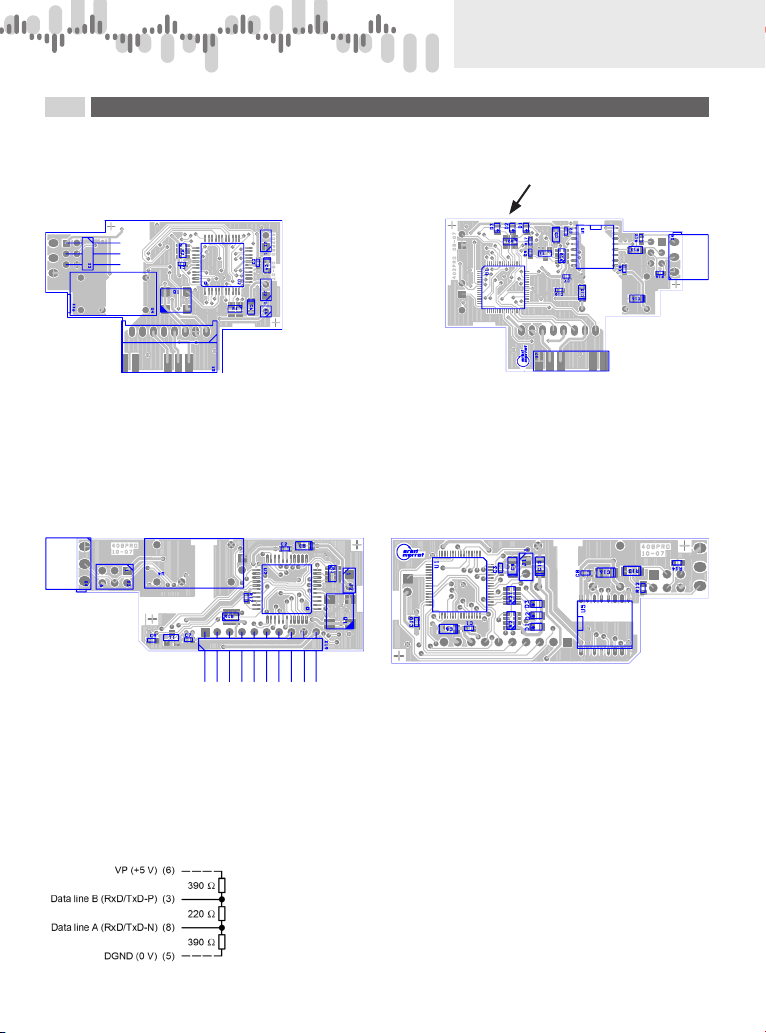
DESCRIPTION
OF COMMUNICATION
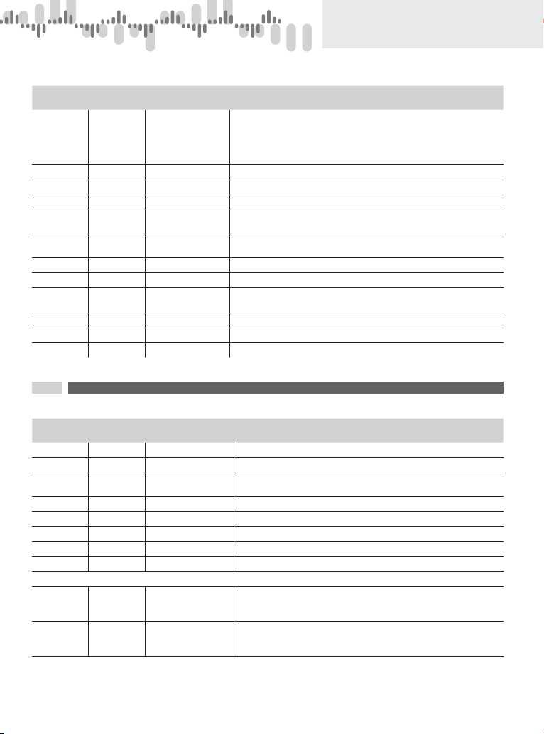
OM Profibus card parameters stored inEEPROM (older version or selection of GSD file in menu - OLD)
Addr. Record
value
Function Manufact.
value
Note
3 131 TimeOut -
OM xxx
4
197…260 ms
Delay for reporting errors in communication with OM xxx instruments
X * 66 ms (inaccuracy from X – 1 to X)
4132 TimeOut -
Profibus
76
aprox. 5 s
Delay for reporting errors in communication to ProfiBus
X * 66 ms (inaccuracy from X – 1 to X)
5133 Transmiss.
delay
8
aprox. 0,6 s
Delay used for downloading in cycles or display projection
(66…131 ms) + X * 66 ms
6 134 Unused (Only for OMX ProfiBus)
7 135 Unused (Only for OMX ProfiBus)
10…29 138…147 Reserve May be used to record values
(Max. 100 000 records (100k Write Cycles))
List of modes („Functions“)
„Function“ Function Note
0 Downloading
values fromOM
xxx instruments
Channel values are downloaded in cycles from theOM xxx instrument with set Address.
Betweendownloadingsthereis a delayinserted,which is setin„Transmission delay“inEEPROM
of the OM Profibus card.
10…15 Displaying
numbersonOM
xxx instrument
Setting display onto decimal number value is repeated in cycles
(function 10 = w/o d.p., 5 = 5 decimal places)
Afterfunction termination (interrupted communication, change of address) the numberstops
displaying itself after approx. 2,5 s
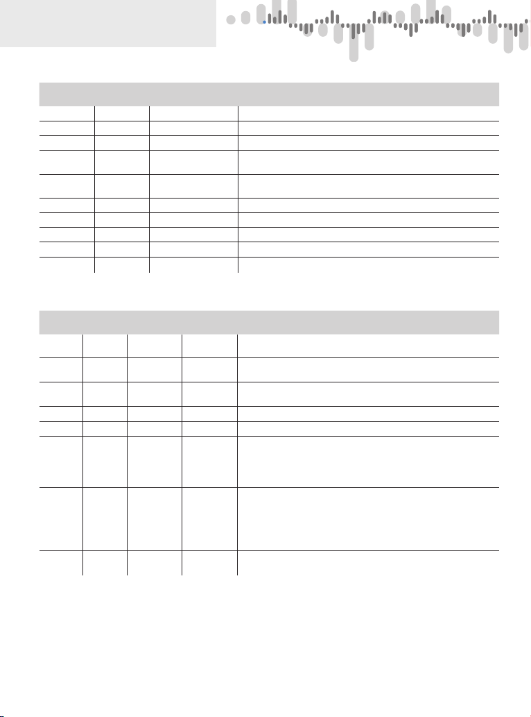
20 Inserting and
projectingdeci-
mal number in
OM xxx instru-
ment
Functions are designed for OM xxxRS instruments, which are able to receive and
process the value (re-calculate, evaluate limit statuses, set the analog output, dis-
play the value in relevant format, change the display colour as per value size).
The value stays projected in the instrument until another value is recorded or the instrument
switches off.
30 Inserting and
projecting inte-
ger number in
OM xxx instru-
ment
Functions are designed for OM xxxRS instruments, which are able to receive and
process the value (re-calculate, evaluate limit statuses, set the analog output, dis-
play the value in relevant format, change the display colour as per value size).
The value stays projected in the instrument until another value is recorded or the instrument
switches off.
100 Projection of
text on display Projection of text on OM xxx instrument display is repeated in cycles.
128 Projection of
OMxxx instrum.
identification
Projection of current OM xxx instrument identification ascertained after the Profibus card
is switched on.
129…130
229…230 Sending
OM command
Upon the change of function OM command is sent to RS 485 line. Functions 129 and130
are waiting for response from OM xxx instrument. Received answer is stored in transmitted
telegramu.
131 Bulk parameter
downloading
The telegram area designed for data is completed with the EEPROM content of OM Profibus
card, in which the card‘s parameters are stored
132 Downloading
SW version
Thetelegramareadesigned fordatais completedwithSWidentificationof the OM Profibuscard
e.g.: „V.1.1.2 - 11/16/07 16:47:20(B737)“, the brackets give a check sum of the card‘s program
memory
133 EEPROM
check sum
The telegram area designed for data is completedwith a check sum of the EEPROM memory
in which the OM Profibus card parameters are stored. E.g..: „1327“
134 Downloading
counters
The telegram area designed for data is completed with service counters readings
(card‘s number of switch-on cycles and total running time) E.g.: „000012;000006“
No data is downloaded unless the „Flag“ value is set to and the „Function“ and„Address“ values are not identical in both telegrams (the received and
the transmitted).
Similar rule applies to an executed command: unless the „Function“ and „Address“ values are not identical in both telegrams (the received and the
transmitted), the function is not performed