Orbit Clear Comfort 83501 User manual

THERMOSTATFEATURES
THERMOSTATINSTRUCTIONS/MODEL
Thank you for purchasing the Clear Comfort™ thermostat from
Orbit™. We are excited to provide a long-lasting thermostat that
blends style with function.
LCD
Mode Switch:
Heat/Off/Cool
Fan Switch:
Auto Fan/Fan On
Room Temperature–Actual temperature of the room
Set Temperature–Desired room temperature
Fahrenheit/Celsius Indicator–
Indicates scale in which temperature is displayed
Mode Indicators–Indicates which mode the system is in: Heat/Off/Cool
Heat Icon–System is in Heating Mode to reach set temperature
Cool Icon–System is in Cooling Mode to reach set temperature
Fan Indicators–Indicates which mode fan is in: Auto Fan/Fan On
Fan Icon–Indicates the fan is energized
Low Baery Indicator–Reminder to change thermostat baeries.
If the baeries are not changed within 7 days aer the Low Baery
Indicator appears on the display, the set temperature will offset by +/- 10°F
as a further reminder. Aer 90 days or less, depending on the condition
of the baeries, the system will turn off and the Low Baery Indicator will
flash on the display.
Temperature Offset–Offset the temperature by +/- 9° F or +/- 4.5° C
Mounting Your Clear Comfort™ Thermostat to the Wall
1. Remove the thermostat body from the base by gently pulling them apart.
2. Place the base flat against the wall by feeding the wires through
the opening below the wiring terminal.
3. Level the base and mark the holes for the mounting screws with a pencil.
4. Remove the base and drill holes at marked positions;
insert the provided wall anchors.
5. Feed wires back through the opening and aach the base to the wall
with the two screws provided.
SYSTEMTYPE
This thermostat is compatible with 1-stage gas furnaces with electric or gas
fan, 1-stage oil systems, 1-stage heat pumps, and 1-stage cooling systems.
Note: This thermostat is not compatible with base board heaters (or other line
voltage heating), multi-stage heating or cooling systems, or 3-wire hydronic systems
INSTALLATION
Tools required for installation:
• Phillips screwdriver
• Wire cuers/strippers
• Drill with / in. (4.8 mm) drill bit
• Level
Tips for Thermostat Location
When replacing an existing thermostat, place your new
Clear Comfort™ thermostat in the same location as the old one, unless
the conditions below suggest otherwise. For a new installation, follow
these guidelines for placement:
• Place the thermostat in a room or hallway that is used oen; position on
an inside wall about 5 . (1.52 m) from the floor.
• Avoid installing the thermostat in unusually heated areas (e.g., near a
television, lamp, radiator, or fireplace), in direct sunlight, or on a wall
that has hot water pipes or that is opposite a stove.
• Avoid installing the thermostat in unusually chilled areas, such as in
a dray area (e.g., stairwell, door, or window), on a wall separating an
unheated room, or where air circulation is poor (e.g., in a corner or
behind a door).
• Avoid installing the thermostat in unusually damp areas as this can lead
to corrosion.
• DO NOT install the thermostat until construction work is complete, dust
free, and painting has been completed.
• If the thermostat housing is cold, wait for it to reach room temperature
before installing.
Removing the Old Thermostat from the Wall
WARNING: Switch off electricity to both the heating (furnace) and cooling
(air conditioner) equipment before proceeding with the following steps:
1. Remove the front cover from the old thermostat.
2. Before removing wires from the old thermostat terminals, take note
of the leers printed near each of the wire terminals.
3. Aach a wiring label (included) to its corresponding wire,
so as to identify the wires’ leer; not the wire color.
4. Aer labeling the wires, remove them from the old thermostat
terminals (usually by releasing clamps or undoing terminal screws
5. Remove the old base from the wall (usually by removing screws).
0/B Y W RC R
G0/B Y W RC R
G
Note: While labeling the individual
wires, DO NOT let the wire fall
back inside the wall, as they can be
difficult to retrieve.
0/B Y W RC R
G0/B Y W RC R
G
Temperature
Adjustment
Buttons
fc
˚set
fan on
auto fan
heat
off
cool
offset
MODE
FAN
Heat Icon F/C Indicator
Set
Temperature
Low
Battery
Indicator
Temperature Offset
Cool Icon
Mode
Indicators
Fan
Indicators
Fan Icon
Room Temperature

Connecting the Wires to the Terminal
1. Strip / in. (9.5 mm) insulation from the end of each wire.
2. Loosen the screws on each terminal. Connect each wire to its
appropriate terminal (matching the label on the wire to the label on
the terminal) and tighten the terminal screw to secure the wire.
3. Completely wrap exposed areas of any unused wire with electrical
tape and push them back into the wall hole.
/ in.
9.5 mm
G0/B Y W
RC
R
G0/B Y W RC R
Note: Do not let the wires touch each
other or other parts of the thermostat.
Be sure that all wires are routed
through the opening on the thermostat
base, then into the proper terminals.
CAUTION: Stripping too much
insulation from the end of a wire
creates the potential for shorting
between wires and could prevent
proper function of the thermostat.
Note: Verify that both systems are working properly
by feeling for warm air when the thermostat is in Heat
Mode and cool air when it is in Cool Mode.
Wire/Terminal Identification:
R Connects to Heat/Fan Transformer
RC Connects to Cool Transformer
W Heating Relay—Energized when heating is triggered
Y Cooling Relay—Energized when cooling is triggered
G Fan Relay—Connects to fan and is energized when
either heating or cooling is triggered
O/B Heat pump changeover valve in Cool (O) or Heat (B)
Completing the Installation
1. Insert two Energizer® or Duracell® alkaline AAA baeries (not
included) into the appropriate spaces on the back of the thermostat
body.
2. Verify that the Fan Jumper is in the correct position for your system
type. (See the "Fan Jumper" section under "Additional Thermostat
Seings.")
3. Install the thermostat body by gently pushing it onto the base until it
"clicks" into place. Verify that there are no gaps in the side housing.
4. Switch on the electricity to both the heating (furnace) and cooling (air
conditioner) sources.
AAA
AAA
RESET
SW1
Electric
Furnace Gas/Oil
Furnace
Heat
(B) Cool
(0)
Heat Pump
RRC W Y O/B G C
601-VO
Note: If the baeries are not changed
within 7 days aer the Low Baery
Indicator appears on the display, the
set temperature will increase by 10°F
in Cooling Mode, or decrease by 10°F
in Heating Mode as a further reminder.
Aer 90 days or less, depending on
the condition of the baeries, the
system will turn off and the Low Baery
Indicator will flash on the display.
BASICTHERMOSTATOPERATION
Heat
Off
Cool
Auto Fan
Fan On
Mode Switch: Slide to the appropriate
mode (Heat/Cool) to achieve the set
temperature.
• Heat—System will operate in
the Heating Mode to reach set
temperature
• Off—System will turn off
• Cool—System will operate in
the Cooling Mode to reach set
temperature
Fan Switch: Slide to appropriate seing
(Auto Fan/Fan On) to indicate fan
operation.
• Auto Fan—Fan will run automatically
until desired temperature is reached
• Fan On—Fan will run continuously
Replacing the Baeries
It is recommended that the baeries in the thermostat be replaced once a
year or before leaving the home for a prolonged period of time.
WARNING: Failure to change baeries in a timely fashion can lead to
uncontrolled heating and cooling.
1. Remove the thermostat body from its base by gently pulling them apart.
2. Turn the thermostat over and remove old baeries.
3. Replace them with fresh Energizer® or Duracell® alkaline AAA baeries,
carefully observing the required polarities.
4. Reinstall the thermostat body onto its base by gently pushing it until it
“clicks” into place.
f
˚set
auto fan
cool
MODE
FAN
Up Arrow
Down Arrow
Reset Buon: Use to reset all
system display seings and
temperature gauges back to
factory defaults. (To gain access
to the Reset Buon, remove the
thermostat body from its base by
gently pulling them apart.)
• Reset Buon—Press and hold
for five seconds to reset your
thermostat
Note: Not having an available wire for
every terminal is normal for some systems.
Note: If you do not have both an R and
RC wire, insert the wire you do have, R
or RC, with the pre-installed jumper wire
(included) that connects the R and RC
terminals. If you have both and R and
RC wire, remove the jumper wire before
connecting the R and RC wires.
Note: If installing your Clear Comfort™ thermostat on a heat pump system,
see the "Installation for Heat Pump Systems" section under "Additional
Thermostat Seings." For electric or oil furnaces, see the additional
instructions section under "Fan Jumper." Set Temperature Adjustment: Use Up
and Down Arrow Buons to raise or
lower the set temperature.
• Up Arrow—Raise set temperature
• Down Arrow—Lower set temperature
THERMOSTATFIGMINIMUMOFFTIMEMU
Off
RESET
Arrow down
Arrow up
Note: Be careful not to touch the
green surface on which the Reset
Buon is mounted, and do not
clean it if dusty.
Fahrenheit or Celsius Adjustment:
Set the temperature to read in either °F or °C.
• Slide the Mode Switch to the Off position (Step 1). While holding the
Reset Buon (on the back of the thermostat body), press the Up Arrow
Buon to toggle between °F or °C (Step 2).

Temperature Offset:
Offset the temperature display to read +/- 9° F or +/- 4.5° C.
• Slide the Mode Switch to the Off position
(Step 1). While holding the Reset Buon (on the back of the thermostat
body), press the Down Arrow Buon until the Offset Indicator appears
(Step 2). Release the Reset Buon. (Do not hold the Reset Buon
for more than five seconds.) Use the Arrow Buons to pick the offset
temperature amount. The thermostat will accept the chosen offset aer
10 seconds of no activity, or by sliding the Mode Switch to Heat or Cool.
THERMOSTATFIGMINIMUMOFFTIMEMU
Off
RESET
Arrow down
Arrow up
Off Up Arrow
Step 1 Step 2
ADDITIONALTHERMOSTATSETTINGS
Seings in this section are not necessary for all systems. These seings,
however, may optimize energy use and comfort levels, especially if a heat
pump system is being used.
System Type Adjustment: Your Clear Comfort™ thermostat is set at
THERMOSTATFIGMINIMUMOFFTIMEMU
Off
RESET
Arrow down
Arrow up
Step 1 Step 2 Step 3 Step 4
THERMOSTATFIGMINIMUMOFFTIMEMU
Off
RESET
Arrow down
Arrow up
Down ArrowOff
or
Installation for Heat Pump Systems:
If installing your Clear Comfort™ thermostat on a heat pump system,
the following instructions are necessary.
• Insert the additional jumper (included) into the Y and W terminals.
• If a B wire is part of your installation, connect it to the O/B terminal.
0/B
Y R
G
0/B
Y W
RC
R
G
AAA
AAA
RESET
SW1
Electric
Furnace Gas/Oil
Furnace
Heat
(B) Cool
(0)
Heat Pump
RRC W Y O/B G C
601-VO
Typical wiring for a heat pump system Jumper position if B wire is connected
Fan Jumper: Correct placement of this jumper optimizes energy use and
comfort levels for the connected system type.
• For electric and heat pump systems, move the jumper located in the top-
right corner on the back of the thermostat body from the Gas/Oil Heat
position on the pins to the Electric Heat position.
• For gas or oil systems, verify that the jumper is in the Gas/Oil
Heat position.
the factory to operate a standard fossil fuel furnace heating system. This
seing can be changed to beer accommodate other heat sources, fan
types or a heat pump system.
• Slide the Mode Switch to the OFF position (Step 1). While holding the
Reset Buon (on the back of the thermostat body), press the Down Arrow
Buon until the Offset Indicator appears (Step 2). Release the Reset
Buon. (Do not hold the Reset Buon for more than five seconds.) Press
the Reset Buon again (Step 3). (The Offset seing will not be lost.) If
using a heat pump, toggle to “HP” using the Up or Down Arrow Buons.
To return to the furnace seing (“F”), press the Up or Down Arrow Buon
(Step 4). The thermostat will accept the seing aer 10 seconds of no
activity, or by sliding the Mode Switch to Heat or Cool.
Minimum Cycle Period Adjustment:
The cycle period is the minimum time in minutes between each heating or
cooling cycle. As a default, your thermostat’s minimum cycle period is set
to optimize energy use and comfort levels. The default can be changed
based on desired cycle times for specified heat systems.
AAA
AAA
RESET
SW1
Electric
Furnace Gas/Oil
Furnace
Heat
(B) Cool
(0)
Heat Pump
RRC W Y O/B G C
601-VO
AAA
AAA
RESET
SW1
Electric
Furnace Gas/Oil
Furnace
Heat
(B) Cool
(0)
Heat Pump
RRC W Y O/B G C
601-VO
Electric furnace Gas/Oil furnace
THERMOSTATFIGMINIMUMOFFTIMEMU
Off
RESET
Arrow down
Arrow up
Off
Down Arrow
Step 1 Step 2
Move the jumper located near the right edge on the back of the
thermostat body from the Cool (O) position on the pins to the Heat (B)
position on the pins. If an O wire is part of your installation, connect it to
the O/B terminal. Leave the jumper on the Cool (O) position.
Minimum Off Time: To help protect the compressor, the system
will wait five minutes aer turning off before turning on again. The
appropriate Mode Indicator Icon (Heat/Cool) will flash on the display
whenever minimum off time is being enforced.
f
˚set
auto fan
cool
MODE
FAN
Icon (snowflake or
flame) flashes while
minimum off time is
being enforced
Recommended Cycle Periods
1-Stage gas furnace heat
with electric fan 12
1-Stage gas furnace heat
with gas fan 12
1-Stage oil furnace 12
Steam and gravity 60
Hot water system 20
High efficiency furnace 20
Electric furnace 6
System Type Cycle Period
(Minutes)
F
HP
1-Stage heat pump 20
Compressor 20

TROUBLESHOOTING
Problem: No heating/cooling system activation
Solution:
1. Verify Mode Switch is in proper Heat or Cool Mode.
2. Replace baeries if necessary. (see Replacing the Baeries section).
3. Check “Set” temperature. Set temperature should read above room
temperature in Heat Mode and below room temperature in Cool Mode.
4. Verify Heating/Cooling power switch isn’t off.
5. Verify that the circuit breaker isn’t tripped.
6. Verify that the furnace door is closed securely.
7. Check for loose or crossed wiring in the thermostat wiring terminal.
8. Verify that copper wires are not exposed and touching other wires.
Problem: No Fan runs continuously
Solution:
1. Let the thermostat sit (do not touch) for 30 minutes to allow
the temperature to stabilize.
2. Verify that the G wire in thermostat wiring terminal
is connected properly.
3. Verify Heating/Cooling power switch isn’t off.
4. Verify that the circuit breaker isn’t tripped.
5. Verify that the furnace door is closed securely.
6. Check for loose or crossed wiring in the thermostat wiring terminal.
7. Verify that copper wires are not exposed and touching other wires.
Problem: Incorrect room temperature
Solution:
1. Let the thermostat sit (do not touch) for 30 minutes to
allow the temperature to stabilize.
THERMOSTATCARE
To prevent damage to the clear thermostat lens, clean with mild soap and
water only, and use a so coon cloth. DO NOT use paper towels or other
abrasive cloths. DO NOT spray any liquid directly onto the thermostat.
THERMOSTATFIGMINIMUMOFFTIMEMU
Off
RESET
Arrow down
Arrow up
THERMOSTATFIGMINIMUMOFFTIMEMU
Off
RESET
Arrow down
Arrow up
THERMOSTATFIGMINIMUMOFFTIMEMU
Off
RESET
Arrow down
Arrow up
Off Down Arrow
Step 3 Step 4 Step 5
Step 6
Step 1 Step 2
or
or
• Slide the Mode Switch to the Off position (Step 1). While holding the
Reset Buon (on the back of the thermostat body), press the Down
Arrow Buon until the Offset Indicator appears. Release the Reset
Buon (Step 2). (Do not hold the Reset Buon for more than five
seconds.) Press the Reset Buon again (Step 3). (The Offset seing
will not be lost.) Use the Up or Down Arrow Buons to select the heat
system being used (Step 4). If using a Heat Pump, select "HP." If using
a furnace, select "F." Once the heating system type has been selected,
press the Reset Buon again to select desired cycle period (Step 5).
If heat pump ("HP") has been selected, use the Up and Down Arrow
Buons to toggle between 60, 20, and 12. If furnace ("F") has been
selected, use the Up and Down Arrow Buons to toggle between 60,
20, 12, and 6 (Step 6). The thermostat will accept the seing by pressing
the Reset Buon, by sliding the Mode Switch to Heat or Cool, or aer
10 seconds of no activity.
2. Check placement of the thermostat. Make sure it’s not
in an unusually dray or heated area.
3. Verify that the wall hole for wires is insulated properly.
4. Check Temperature Offset (see “Temperature Offset” section).
Problem: Not reaching set temperature
Solution:
1. Verify that the Mode Switch is in proper Heat or Cool Mode.
2. Verify that Heating/Cooling systems are working properly. (See No
Heating/Cooling System Activation in Troubleshooting section above.)
3. Check for loose or crossed wiring in the thermostat wiring terminal.
4. Check Temperature Offset (see “Temperature Offset” section).
5. Check placement of thermostat; make sure it’s not in an unusually
dray or heated area.
6. Verify that the wall hole for wires is insulated properly.
Problem: Wrong temperature scale displayed
Solution: See “Fahrenheit or Celsius Adjustment” section.
Problem: Display is blank/Low Baery Indicator on
Solution:
1. Replace baeries (see “Replacing the Baeries” section).
2. Check for loose or crossed wiring in thermostat wiring terminal.
Problem: Heat/cool system doesn’t respond immediately
Solution:
1. To protect your compressor, the thermostat default is to wait five
minutes before responding. For more information, see “Minimum Off
Time” section.
2. If the problem persists aer waiting five minutes, check baeries.
Replace if necessary (see “Replacing the Baeries” section).
Problem: Set Temperature is 10°F above (in Cooling Mode) or 10°F below
(in Heating Mode) desired temperature
Solution: Replace baeries. (see “Replacing the Baeries” section).
Problem: System turns on too frequently
Solution: The Orbit™ Clear Comfort™ thermostat uses smart logic to turn
once every cycle period to maximize comfort and temperature stability.
To adjust the cycle period, see the “Minimum Cycle Period Adjustment”
section under “Additional Thermostat Seings.”

TECHNICALSUPPORTINFORMATION
For technical assistance, please call:
1-800-488-6156 or 1-801-299-5555.
Before returning this thermostat to the store, please call:
1-800-488-6156 or 1-801-299-5555.
WARRANTYINFORMATION
Orbit, Inc. warrants to its customers that its products will be free
from defects in materials and workmanship for a period of three
years from the date of purchase.
We will replace, free of charge, the defective part or parts
found to be defective under normal use and service for a
period of up to three years aer purchase (proof of purchase
required). We reserve the right to inspect the defective part
prior to replacement.
Orbit, Inc. will not be responsible for consequential or incidental
cost or damage caused by the product failure. Orbit, Inc. liability
under this warranty is limited solely to the replacement or repair
of defective parts.
To exercise your warranty, return the unit to the dealer with a
copy of your sales receipt.
All trade names are registered trademarks of the respective
manufacturers listed.
www.orbitonline.com
Orbit, Inc.
North Salt Lake, UT 84054 Model 83501
PN 83501-24 rC

INSTRUCCIONESPARAELTERMOSTATO/MODELO
Gracias por comprar el termostato Clear Comfort™ de Orbit™.
Estamos entusiasmados por proporcionar un termostato duradero
que integra estilo y funcionalidad.
Temperatura ambiente: Temperatura real de la habitación
Regular la temperatura: Temperatura ambiente deseada
Indicador Fahrenheit/Celsius: Indica la escala en la cual se muestra
la temperatura
Indicadores de modo: Indica en qué modo se encuentra el sistema: Calefacción/
Apagado/Enfriamiento
Icono de calefacción: El sistema se encuentra en modo Calefacción
para regular la temperatura
Icono de enfriamiento: El sistema se encuentra en modo Enfriamiento para
regular la temperatura
Indicadores de ventilador: Indica en qué modo se encuentra el ventilador:
Ventilador automático/Ventilador encendido
Icono de ventilador: Indica que el ventilador está encendido
Indicador de batería baja: Recordatorio para cambiar las baterías del termostato.
Si las baterías no se cambian dentro de 7 días después de que el indicador de
batería baja aparece en la pantalla, la regulación de la temperatura se desviará
en +/- -12,2° C (10° F) a modo de recordatorio. Después de 90 días o menos,
dependiendo de la condición de las baterías, el sistema se apagará y el indicador
de batería baja titilará en la pantalla.
Desviación de la temperatura: Desvía la temperatura en +/- 9° F o +/- 4.5° C
INSTALACIÓN
Herramientas necesarias para la instalación:
• Destornillador Phillips
• Pinzas cortacables/pelacables
• Taladro con broca de 3/16 pulg (4,8 mm)
• Nivel
Consejos para ubicar el termostato
Al reemplazar un termostato existente, ubique su termostato Clear Comfort™
nuevo en el lugar del antiguo, a menos que las condiciones a continuación lo
sugieran de otro modo. Para la ubicación de una instalación nueva, siga estas
pautas:
• Ubique el termostato en una habitación o pasillo que use a menudo, en una
pared interior, a aproximadamente 1,53 m (5 pies) del piso.
• Evite instalar el termostato en áreas excepcionalmente calefaccionadas (por
ejemplo, cerca de una televisión, lámpara, radiador o chimenea), bajo la luz
directa del sol, o en una pared que cuenta con tuberías de agua caliente o que
se encuentra al otro lado de una estufa.
• Evite instalar el termostato en áreas excepcionalmente frías, como un área
donde hay viento (por ejemplo, cerca de las escaleras, puertas o ventanas),
en una pared que separa una habitación sin calefacción o donde hay una mala
circulación del aire (por ejemplo, en una esquina o detrás de una puerta).
• Evite instalar el termostato en áreas excepcionalmente húmedas, ya que esto
puede provocar corrosión.
• NO instale el termostato hasta que trabajo de construcción esté completo, libre
de polvo y pintado.
• Si la caja del termostato está fría, espere que alcance la temperatura ambiente
antes de instalarlo.
Para retirar el termostato antiguo de la pared
ADVERTENCIA: Desconecte la electricidad del equipo de calefacción (calefacción)
y enfriamiento (acondicionador de aire) antes de continuar con los siguientes
pasos:
1. Retire la cubierta frontal del termostato antiguo.
2. Antes de retirar los cables de los terminales del termostato antiguo, tome nota
de las letras impresas cerca de cada uno de los terminales de cables.
3. Coloque una etiqueta para cableado (incluida) al cable correspondiente, para
identificar la letra de los cables, no los colores.
4. Después de etiquetar los cables, retírelos de los terminales del termostato
antiguo (normalmente, soltando la abrazaderas o los tornillos del terminal).
5. Retire la base antigua de la pared (normalmente, retirando los tornillos).
Para montar su termostato Clear Comfort™ en la pared
1. Retire el cuerpo del termostato de la base retirándolo suavemente.
2. Coloque la base contra la pared, alimentando los cables por la abertura debajo
del terminal de cableado.
3. Nivele la base y marque los orificios de los tornillos de montaje con un lápiz.
4. Retire la base y taladre orificios en las ubicaciones marcadas; inserte las anclas
de expansión proporcionadas.
5. Pase los cables por la abertura y fije la base a la pared con los dos tornillos
proporcionados.
0/B Y W RC R
G0/B Y W RC R
G
Nota: Al etiquetar los cables
individuales, NO permita que el
cable caiga dentro de la pared, ya
que podría ser dicil recuperarlos.
0/B Y W RC R
G0/B Y W RC R
G
CARACTERÍSTICASDELTERMOSTATO
Botones de
ajuste de
temperatura
LCD
Interruptor
de modo:
Calefacción/
Apagado/
Enfriamiento
Interruptor para
ventilador:
Ventilador automático/
Ventilador encendido
fc
˚set
fan on
auto fan
heat
off
cool
offset
MODE
FAN
Icono de
calefacción
Indicador
deF/C
Regular la
temperatura
Indicador
de batería
baja
Desviación de la
temperatura
Icono de
enfriamiento
Indicadores
de modo
Indicadores
de ventilador
Icono de
ventilador
Temperatura ambiente
TIPODESISTEMA
Este termostato es compatible con sistemas de calefacción a gas de 1 fase, con
ventilador eléctrico o a gas, sistemas de aceite de 1 fase, bombas de calor de 1 fase
y sistemas de enfriamiento de 1 fase.
Nota: Este termostato no es compatible con calentadores de zócalo (u otra
calefacción de voltaje de la línea), sistemas de calefacción o enfriamiento de varias
fases, o sistemas hidrónicos de 3 cables.

Para conectar los cables al terminal
1. Pele 9,53 mm (3/8 pulg) del aislamiento del extremo de cada cable.
2. Afloje los tornillos de cada terminal. Conecte cada cable a su terminal
correspondiente (haciendo coincidir la etiqueta en el cable con la etiqueta
en el terminal) y apretando el tornillo del terminal para asegurar el cable.
3. Envuelva completamente las áreas expuestas de cable que no haya utilizado
con cinta aislante y colóquelo nuevamente en el orificio de la pared.
G0/B Y W
RC
R
G0/B Y W RC R
Nota: No permita que los cables se
toquen entre sí o que toquen otras
piezas del termostato. Asegúrese de
que todos los cables pasen por la
abertura de la base del termostato
y luego por los terminales correspondientes.
PRECAUCIÓN: Pelar demasiado
aislamiento del extremo de un cable
provoca riesgo de cortocircuito entre los
cables y podría evitar el funcionamiento
adecuado del termostato.
Nota: Compruebe que ambos sistemas funcionen correctamente
al sentir el aire caliente cuando el termostato esté en modo
Calefacción y el aire frío cuando esté en modo Enfriamiento.
Identificación de los cables/terminales
R Conecta al transformador de calefacción/ventilador
RC Conecta al transformador de enfriamiento
W Relé de calefacción: Se enciende cuando la calefacción está activada
Y Relé de enfriamiento: Se enciende cuando el enfriamiento está activado
G Relé de ventilador: Se conecta al ventilador y se enciende cuando la
calefacción o el enfriamiento están activados
O/B La válvula del conmutador de la bomba de calor se encuentra en
Enfriamiento (O) o Calefacción (B)
Para completar la instalación
1. Inserte dos baterías alcalinas AAA Energizer® o Duracell® (no incluidas) en los
espacios correspondientes, en la parte posterior del cuerpo del termostato.
2. Compruebe que el puente del ventilador esté en la posición correcta
para su tipo de sistema (consulte la sección “Puente del ventilador” en
“Configuraciones adicionales del termostato”).
3. Instale el cuerpo del termostato presionándolo suavemente en la base hasta
que calce en su lugar. Compruebe que no queden espacios en la caja lateral.
4. Conecte la electricidad a las fuentes de calefacción (calefacción) y enfriamiento
(acondicionador de aire).
Para reemplazar las baterías
Se recomienda reemplazar las baterías del termostato una vez al año o antes de
abandonar la casa por un período prolongado.
ADVERTENCIA: No cambiar las baterías de forma oportuna puede provocar
calefacción y enfriamiento descontrolado.
1. Retire el cuerpo del termostato de su base retirándolo suavemente.
2. Gire el termostato y retire las baterías antiguas.
3. Reemplácelas con baterías AAA alcalinas Energizer® o Duracell® nuevas,
observe atentamente las polaridades requeridas.
4. Vuelva a instalar el cuerpo del termostato en su base, presionándolo suavemente
hasta que calce en su lugar.
Ajuste de grados Fahrenheit o Celsius:
Regule la lectura de la temperatura en °F o °C.
• Coloque el interruptor de modo en la posición Apagado (Paso 1). Mientras
mantiene presionado el botón Restablecer (al reverso del cuerpo del termostato),
presione el botón de flecha Arriba para alternar entre °F o °C (Paso 2).
Nota: Es normal que algunos sistemas no
cuenten con un cable para cada terminal.
Nota: Si no tiene los cables R y RC, inserte el
cable que tenga, R o RC, con el conductor del
puente preinstalado (incluido) que conecta
los terminales R y RC. Si posee los cables R
y RC, retire el conductor del puente antes de
conectar los cables R y RC.
Nota: Si instala el termostato Clear Comfort™ en un sistema de
bomba de calor, consulte la sección “Instalación de sistemas de
bomba de calor” en “Configuraciones adicionales del termostato”.
Para calefacción eléctrica o con aceite, consulte la sección de
instrucciones adicionales en “Puente del ventilador”.
/ pulg
9.5 mm
AAA
AAA
RESET
SW1
Electric
Furnace Gas/Oil
Furnace
Heat
(B) Cool
(0)
Heat Pump
RRC W Y O/B G C
601-VO
Nota: Si las baterías no se cambian
dentro de 7 días después de que el
indicador de batería baja aparece
en la pantalla, la regulación de la
temperatura aumentará -12,2° C (10° F)
en el modo Enfriamiento o disminuirá
-12,2° C (10° F) en el modo Calefacción
a modo de recordatorio. Después de
90 días o menos, dependiendo de la
condición de las baterías, el sistema se
apagará y el indicador de batería baja
titilará en la pantalla.
OPERACIÓNBÁSICADELTERMOSTATO
Interruptor de modo: Coloque en el modo
correspondiente (Calefacción/Enfriamiento)
para regular la temperatura.
• Calefacción: El sistema operará en modo
Calefacción para regular
la temperatura
• Apagado: El sistema se apagará
• Enfriamiento: El sistema operará en modo
Enfriamiento para regular la temperatura
Interruptor para ventilador: Coloque
en el modo correspondiente (Ventilador
automático/Ventilador encendido) para
indicar la operación del ventilador.
• Ventilador automático: El ventilador
funcionará automáticamente hasta
alcanzar la temperatura deseada
• Ventilador encendido: El ventilador
funcionará en forma continua
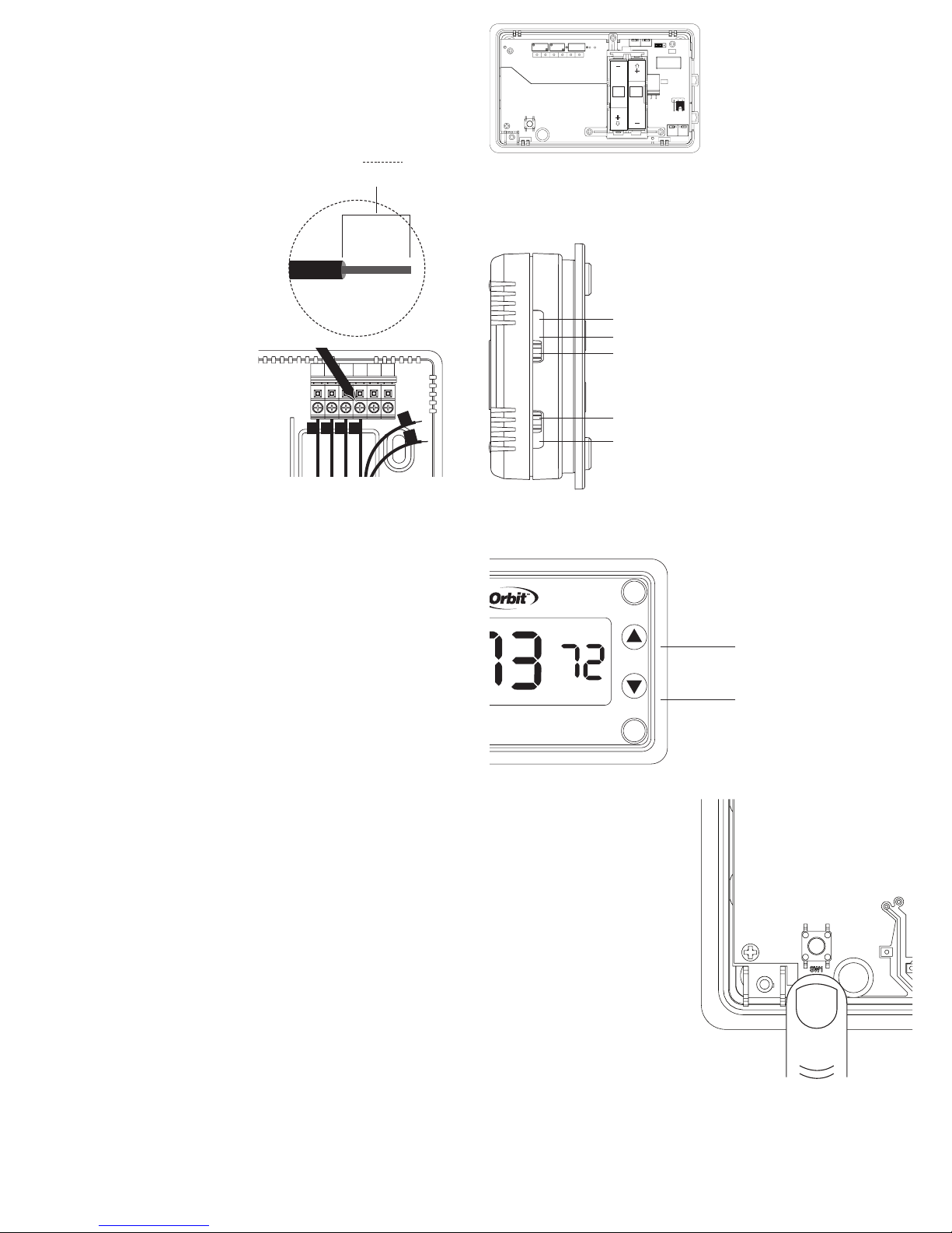
Botón Restablecer: Úselo
para restablecer todas las
configuraciones en la pantalla del
sistema y volver los indicadores de
temperatura a los predeterminados
de fábrica (para obtener acceso
al botón Restablecer, retire el
cuerpo del termostato de su base
retirándolo suavemente).
• Botón Restablecer: Presiónelo y
manténgalo presionado durante
5 segundos para restablecer el
termostato.
Ajuste de regulación de la temperatura:
Use los botones de flecha Arriba y Abajo
para aumentar o disminuir la regulación de
la temperatura.
• Flecha Arriba: Aumenta la temperatura
• Flecha Abajo: Disminuye la temperatura
THERMOSTATFIGMINIMUMOFFTIMEMU
Off
RESET
Arrow down
Arrow up
Nota: Tenga cuidado de no tocar
la superficie verde en la cual está
montado el botón Restablecer, así
como de no limpiarla si está sucia.
Calor
Apagado
Frío
Ventilador
automático
Ventilador
encendido
f
˚set
auto fan
cool
MODE
FAN
Flecha Arriba
Flecha Abajo

Desviación de la temperatura:
Desvíe la pantalla de la temperatura para que se lea +/- 12,8° C o +/- 9° F.
• Coloque el interruptor de modo en la posición Apagado (Paso 1). Mientras
mantiene presionado el botón Restablecer (al reverso del cuerpo del
termostato), presione el botón de flecha Abajo hasta que aparezca el indicador
de desviación (Paso 2). Suelte el botón Restablecer (no mantenga presionado el
botón Restablecer durante más de cinco segundos). Use los botones de flecha
para seleccionar la temperatura de desvío. El termostato aceptará la desviación
elegida después de 10 segundos de inactividad, o al colocar el interruptor de
modo en Calefacción o Enfriamiento.
CONFIGURACIONESADICIONALESDELTERMOSTATO
Las configuraciones en esta sección no son necesarias para todos los sistemas. Sin
embargo, estas configuraciones podrían optimizar el uso de la energía y los niveles
de comodidad, en especial si se está utilizando un sistema de bomba de calor.
Ajuste del tipo de sistema: La configuración de fábrica del termostato Clear
Comfort™ está realizada para operar un sistema de calefacción con combustible
fósil estándar. Esta configuración puede cambiarse para adaptarse de mejor
manera a otras fuentes de calefacción, tipos de ventilador o a un sistema de
bomba de calor.
• Coloque el interruptor de modo en la posición APAGADO (Paso 1). Mientras
mantiene presionado el botón Restablecer (al reverso del cuerpo del
termostato), presione el botón de flecha Abajo hasta que aparezca el indicador
de desviación (Paso 2). Suelte el botón Restablecer (no mantenga presionado
el botón Restablecer durante más de cinco segundos). Presione nuevamente el
botón Restablecer (Paso 3) (la configuración de desviación no se perderá). Si usa
una bomba de calor, alterne a “HP” usando los botones de flecha Arriba o Abajo.
Para volver a la configuración de calefacción (“F”), presione el botón de flecha
Arriba o Abajo (Paso 4). El termostato aceptará la configuración después de 10
segundos de inactividad, o al colocar el interruptor de modo en Calefacción o
Enfriamiento.
THERMOSTATFIGMINIMUMOFFTIMEMU
Off
RESET
Arrow down
Arrow up
Step 1 Step 2 Step 3 Step 4
THERMOSTATFIGMINIMUMOFFTIMEMU
Off
RESET
Arrow down
Arrow up
Down ArrowOff
or
nstalación de sistemas de bombas de calor: Si instala el termostato Clear
Comfort™ en un sistema de bomba de calor, las siguientes instrucciones son
necesarias.
• Inserte el puente adicional (incluido) en los terminales Y y W.
• Si un cable B es parte de su instalación, conéctelo al terminal O/B. Mueva el
puente ubicado cerca del borde derecho al reverso del cuerpo del termostato de
Puente del ventilador: La ubicación correcta de este puente optimiza el uso de la
energía y los niveles de comodidad para el tema de sistema conectado.
• Para los sistemas eléctrico y de bomba de calor, mueva el puente ubicado en la
esquina superior derecha al reverso del cuerpo del termostato de la posición
Calefacción a gas/con aceite en los pasadores a la posición Calefacción eléctrica.
• Para los sistemas a gas o con aceite, compruebe que el puente esté en la posición
Calefacción a gas/con aceite.
Ajuste del período de tiempo mínimo:
El período de tiempo es el tiempo mínimo en minutos entre cada tiempo de
calefacción o enfriamiento. La configuración predeterminada del período de
tiempo mínimo del termostato está establecida para optimizar el uso de energía y
los niveles de comodidad. La configuración predeterminada puede cambiarse de
acuerdo con los tiempos deseados para sistemas de calefacción específicos.
la posición Enfriamiento (O) en los pasadores a la posición Calefacción (B) en los
pasadores. Si un cable O es parte de su instalación, conéctelo al terminal O/B.
Deje el puente en la posición Enfriamiento (O).
Tiempo mínimo de apagado: Para ayudar a proteger el compresor, el sistema
esperará cinco minutos después del apagado antes de volver a encenderlo.
El icono indicador de modo correspondiente (Calefacción/Enfriamiento)
titilará en la pantalla cada vez que se ponga en ejecución el tiempo mínimo de
apagado.
f
˚set
auto fan
cool
MODE
FAN
Cuando se pone en
ejecución el tiempo
mínimo de apagado,
el icono (copo de
nieve o llama)
destella
THERMOSTATFIGMINIMUMOFFTIMEMU
Off
RESET
Arrow down
Arrow up
Apagado Flecha
Arriba
Paso 1 Paso 2
THERMOSTATFIGMINIMUMOFFTIMEMU
Off
RESET
Arrow down
Arrow up
Apagado
Flecha Abajo
Paso 1 Paso 2
0/B
Y R
G
0/B
Y W
RC
R
G
AAA
AAA
RESET
SW1
Electric
Furnace Gas/Oil
Furnace
Heat
(B) Cool
(0)
Heat Pump
RRC W Y O/B G C
601-VO
Cableado típico de un sistema
de bomba de calor
Posición del puente si el
cable B está conectado
AAA
AAA
RESET
SW1
Electric
Furnace Gas/Oil
Furnace
Heat
(B) Cool
(0)
Heat Pump
RRC W Y O/B G C
601-VO
AAA
AAA
RESET
SW1
Electric
Furnace Gas/Oil
Furnace
Heat
(B) Cool
(0)
Heat Pump
RRC W Y O/B G C
601-VO
Calefacción eléctrica Calefacción a gas/con aceite
Períodos de tiempo recomendados
Calefacción a gas de 1 fase con
ventilador eléctrico 12
Calefacción a gas de 1 fase con
ventilador a gas 12
Calefacción a gas de 1 fase 12
Vapor y gravedad 60
Sistema de agua caliente 20
Calefacción de alta eficiencia 20
Calefacción eléctrica 6
Tipo de sistema Período de tiempo
(minutos)
F
HP
Bomba de calor de 1 fase 20
Compresor 20

SOLUCIÓNDEPROBLEMAS
Problema:
No se activa el sistema de calefacción/enfriamiento
Solución:
1. Compruebe que el interruptor de modo esté en modo Calefacción o
Enfriamiento, según corresponda.
2. Revise las baterías y reemplácelas si es necesario (consulte la sección Para
reemplazar las baterías).
3. Compruebe la “Regulación” de la temperatura. Esta debería leerse “sobre
la temperatura ambiente” en el modo Calefacción y “bajo la temperatura
ambiente” en el modo Enfriamiento.
4. Compruebe que el interruptor de encendido de Calefacción/Enfriamiento no
esté apagado.
5. Compruebe que el interruptor de alimentación no se haya disparado.
6. Compruebe que la puerta de la calefacción esté cerrada
en forma segura.
7. Revise los cables sueltos o cruzados en el terminal de cableado
del termostato.
8. Compruebe que los cables de cobre no estén expuestos y que no toquen otros
cables.
Problema:
El ventilador no funciona/funciona en forma continua
Solución:
1. Deje reposar el termostato (no lo toque) durante 30 minutos, para permitir que
se estabilice la temperatura.
2. Compruebe que el cable G en el terminal de cableado del termostato esté bien
conectado.
3. Compruebe que el interruptor de encendido de Calefacción/Enfriamiento no
esté apagado.
4. Compruebe que el interruptor de alimentación no se haya disparado.
5. Compruebe que la puerta de la calefacción esté cerrada
en forma segura.
CUIDADODELTERMOSTATO
Para evitar daños en el lente transparente del termostato, limpie solamente con
agua, jabón suave un paño suave de algodón. NO use toallas de papel u otros paños
abrasivos. NO rocíe ningún tipo de líquido directamente en el termostato.
• Coloque el interruptor de modo en la posición Apagado (Paso 1). Mientras
mantiene presionado el botón Restablecer (al reverso del cuerpo del
termostato), presione el botón de flecha Abajo hasta que aparezca el indicador
de desviación. Suelte el botón Restablecer (Paso 2) (no mantenga presionado
el botón Restablecer durante más de cinco segundos). Presione nuevamente el
botón Restablecer (Paso 3) (la configuración de desviación no se perderá). Use
los botonas de flecha Arriba o Abajo para seleccionar el sistema de calefacción
que se utilizará (Paso 4). Si utiliza una bomba de calor, seleccione “HP”. Si
utiliza calefacción, seleccione “F”. Una vez seleccionado el tipo de sistema de
calefacción, presione nuevamente el botón Restablecer para seleccionar el
período de tiempo deseado (Paso 5). Si se ha seleccionado la bomba de calor
(“HP”), use los botones de flecha Arriba y Abajo para alternar entre 60, 20 y
12. Si se ha seleccionado calefacción (“F”), use los botones de flecha Arriba
y Abajo para alternar entre 60, 20, 12 y 6 (Paso 6). El termostato aceptará la
configuración al presionar el botón Restablecer, al colocar el interruptor de
modo en Calefacción o Enfriamiento o después de 10 segundos de inactividad.
6. Revise los cables sueltos o cruzados en el terminal de cableado
del termostato.
7. Compruebe que los cables de cobre no estén expuestos y que no toquen otros
cables.
Problema:
Temperatura ambiente incorrecta
Solución:
1. Deje reposar el termostato (no lo toque) durante 30 minutos, para permitir que
se estabilice la temperatura.
2. Revise la ubicación del termostato. Asegúrese de que no sea un área donde
excepcionalmente hay viento o un área calefaccionada.
3. Compruebe que el orificio de la pared para los cables cuente con aislamiento
adecuado.
4. Revise la desviación de la temperatura (consulte la sección “Desviación de la
temperatura”)
Problema:
No regula la temperatura
Solución:
1. Compruebe que el interruptor de modo esté en modo Calefacción o
Enfriamiento, según corresponda.
2. Compruebe que los sistemas de Calefacción/Enfriamiento funcionen
correctamente (Consulte No se activa el sistema de calefacción/enfriamiento
en la sección Solución de problemas).
3. Revise los cables sueltos o cruzados en el terminal de cableado
del termostato.
4. Revise la desviación de la temperatura (consulte la sección “Desviación de la
temperatura”).
5. Revise la ubicación del termostato; asegúrese de que no sea un área donde
excepcionalmente hay viento o un área calefaccionada.
6. Compruebe que el orificio de la pared para los cables cuente con aislamiento
adecuado.
Problema:
Se muestra la escala de temperatura incorrecta
Solución:
1. Consulte la sección “Ajuste de grados Fahrenheit o Celsius”.
Problema:
La pantalla está en blanco/está activado el indicador de batería baja
Problema:
1. Reemplace las baterías (consulte la sección “Para reemplazar las baterías”).
2. Revise los cables sueltos o cruzados en el terminal de cableado
del termostato.
Problema:
El sistema de calefacción/enfriamiento no responde inmediatamente
Solución:
1. Para proteger el compresor, la configuración predeterminada del termostato
esperará cinco minutos antes de responder. Para obtener más información,
consulte la sección “Tiempo mínimo de apagado”.
2. Si el problema continúa después de esperar cinco minutos, revise las baterías
y reemplácelas si es necesario (consulte la sección “Para reemplazar las
baterías”).
Problema:
La regulación de la temperatura es superior en 10 °F (en modo Enfriamiento) o
inferior en 10 °F (en modo Calefacción) a la temperatura deseada
Solución:
1. Revise las baterías y reemplácelas si es necesario (consulte la sección “Para
reemplazar las baterías”).
Problema:
El sistema se enciente con demasiada frecuencia
Solución:
1. El termostato Clear Comfort™ de Orbit™ utiliza la lógica inteligente para
encenderse una vez por período de tiempo, de modo de maximizar la
comodidad y estabilidad de la temperatura. Para ajustar el período de tiempo,
consulte la sección “Ajuste del período de tiempo mínimo” en “Configuraciones
adicionales del termostato”.
THERMOSTATFIGMINIMUMOFFTIMEMU
Off
RESET
Arrow down
Arrow up
THERMOSTATFIGMINIMUMOFFTIMEMU
Off
RESET
Arrow down
Arrow up
THERMOSTATFIGMINIMUMOFFTIMEMU
Off
RESET
Arrow down
Arrow up
Apagado
Paso 3 Paso 4 Paso 5 Paso 6
Paso 1 Paso 2
or or
Flecha Abajo

INFORMACIÓNDESOPORTETÉCNICO
Para asistencia técnica, llame al:
1-800-488-6156 o 1-801-299-5555.
Antes de devolver este termostato a la tienda, llame al:
1-800-488-6156 o 1-801-299-5555.
INFORMACIÓNDELAGARANTÍA
Orbit, Inc. garantiza a sus clientes que sus productos no tendrán
defectos en los materiales ni en la mano de obra durante un
período de tres años a partir de la fecha de compra.
Reemplazaremos, sin cargo, el componente o los componentes
defectuosos en condiciones de uso y mantenimiento normales
durante un período de hasta tres años después de la compra (se
requiere comprobante de compra). Nos reservamos el derecho
de inspeccionar el componente defectuoso antes
de reemplazarlo.
Orbit, Inc. no se responsabilizará por los daños ni costos
incidentales ni resultantes ocasionados por la falla del producto.
La responsabilidad de Orbit, Inc. en virtud de esta garantía
se limita únicamente al reemplazo o a la reparación de los
componentes defectuosos.
Para hacer valer su garantía, devuelva la unidad a su distribuidor
con una copia del recibo de venta.
Todos los nombres comerciales son marcas comerciales
registradas de los fabricantes respectivos mencionados.
www.orbitonline.com
Orbit, Inc.
North Salt Lake, UT 84054 Modelo 83501
PN 83501-24N rA
Table of contents
Languages:
Other Orbit Thermostat manuals
Popular Thermostat manuals by other brands

HAVKON INSTRUMENTS
HAVKON INSTRUMENTS HCT.2401 user manual

Aube Technologies
Aube Technologies TH147E Installation and user guide

Carrier
Carrier Totaline Star P474-1010 owner's manual

Protherm
Protherm Exabasic quick start guide

TemperZone
TemperZone TZT-701 user manual

Ideal Boilers
Ideal Boilers touch quick start guide