Orgautomatech Key2Midi User manual

Key2Midi 64 et 32
Encoder MIDI board
User manual
Preamble
The Key2Midi board isn't a musical instrument by itself. It is intended to be
the interface between an accordion or organ keyboard and a MIDI music
sound module or any electronic equipment responding to Midi standard.
The purpose of this user manual is not to e plain the MIDI protocol. It is
assumed the user has a basic knowledge of this
Main features:
•64, 48 or 32 direct input, non-multiple ed. Multiple ing is done in the
board itself
•inputs can be +5v (High) or Gnd (Low)

• 2 analog inputs sending Midi messages e pression and volume.
•Sizes: 40 * 168 mm (64) , 40*115 (32), 40*135 (48)
•The MIDI channel can be changed on the card by a push buttons and
led, or by MIDI. This simple procedure is e plained later in this
document.
•Very easy mapping of sent notes by the freeware « PARAMETOR ».
This simple procedure is e plained later in this document.
•Protection against bad polarity
•Compatible with any instrument responding to Midi standard
•In case of many keyboards, boards can be chained.
•Wiring of inputs by 16 pin connectors and ribbon cable, available in
option here: accessories
•To send a midi note, you have to apply a 5 volt voltage (or Gnd) to one
input.
•The board can supply the power for optical rank if needed, with limit
of 700mA. Some optical kits will be available soon.
Electrical features:
The board needs a power supply that gives between 8 and 15 volt DC. A small
phone (old fashion) charger (8-12volt) will work fine if there is no optical
reader to power.
Please, avoid using an old transformer and just a diode bridge rectifier.
There are 4 16 pin connectors on board (2 for K2M 32). You can wire there
directly your key contacts with 16 wire ribbons. Common of all contacts is the
+5v on the board, so then when you press a key, the +5v is going to
corresponding input.
Ribbon cable and female connectors are available on Orgautomatech site,
page “accessories”

#1 is the red wire, look at the picture closely.
Here is on the picture, the right way to connect the ribbon.
With for 50cm long ribbon, you can connect all the keys of a standard
keyboard, if you place the board in the middle, of course.
You can possibly, power an optical reader rank, under limit of 500 mA.
Please, adapt the power supply to this consumption. If it is over this limit,
please power the optical equipment directly with a different power supply, just
let the Gnd common to the 2 power supplies.
The inputs are “pulled down” by a 22ko resistor. Take this in account for your
photo-transistors.
L- modes
The normal mode is H (high), ie the inputs are active (sending an note ON)
when we apply +5 volts.
Alternatively, in L mode, the inputs are active and sending the note ON when
the Gnd is applied to the input. This may be necessary, for e ample, with hall
effect detectors, to avoid over-consumption. You just need to change the
position jumper to choose your mode.

Analog inputs
These new K2M cards have 2 analog inputs, sending the Midi e pression and
volume messages. You will need to connect (quality) 10k potentiometers to
the points marked A1 and A2, A1 is the input for the e pression, A2 for the
volume, as well as on the + and gnd, see photo.
Ask me before ordering if you want the board to send another control change.
If you do not use these inputs, you must leave the jumpers in place, as in the
photo, linking the A1 and A2 to +5v. In this case, at startup, two messages

(e pression and volume) will be sent with a value of 127.
MIDI wiring
Wire a Midi cable between your K2M MIDI OUT and your midi sound
module MIDI IN.
The MIDI IN socket in for wiring another K2M board, in case of another
keyboard. Note messages are driven to the MIDI OUT.
Please note that you should not connect the K2M MIDI IN to your computer
MIDI OUT. This would cause problems, especially if your sequencer MIDI
THRU is on: an undesirable loop would result!
There is an e ception to this rule: when you are mapping the notes with
Parametor. In that case, nothing must be connected to the K2M MIDI OUT.
Midi channel setting
The MIDI channel can be set easily, without changing anything else, and
without a computer, directly on the board.
To verify or check the board’s currently set MIDI channel: push the
«channel» button once and count the number of red LED flashes. That
number is the MIDI channel.
To set the MIDI channel:
•1. Push the setting button – the green led switches off. While holding
it down, press the channel button as many times as the channel you
want, for e ample once for channel 1, twice for channel 2, etc. Don't
be to quick. Each press must last at least ½ second.
•2. When it's done, release the setting button. The green led switches on
again. The new channel is recorded.
•3. You can verify your setting by pushing the channel button and count
the number of red LED flashes
This procedure is needed only once. The board stores the midi channel in
memory even when it is switched off.
Channel can also be changed by Orgautomatech freeware “Parametor”.

Notes mapping
Key2Midi board cans send 64 (or 32, or 48) MIDI notes, to choose among
128.
Default factory mapping is MIDI number 48 to 111. If this doesn't suit your
needs, you will have to attribute a MIDI number to each of the inputs. You'll
need to do this only once, as board stores them in memory even when
switched off. You do not have to follow a particular order, notes can be
ascending or descending, chromatic or not. However, you should not have the
same note twice.
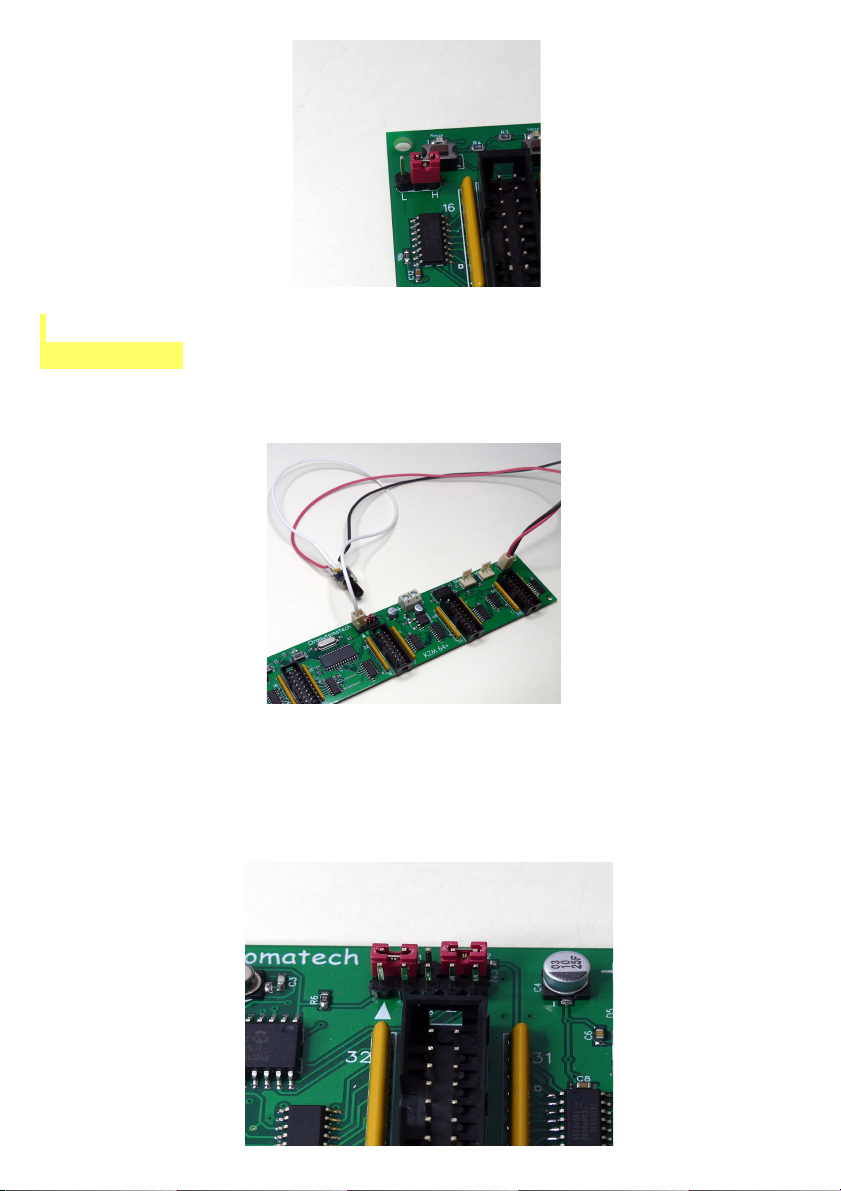
Program your boards one by one, without connect MIDI OUT of one to MIDI
IN of another!
The procedure is very simple, you need JAVA to be installed on your
computer (Windows or Mac as well). Then, you can download PARAMETOR
here: http://www.blog4ever.com/blog/fichier-653148-7107168-69227.html
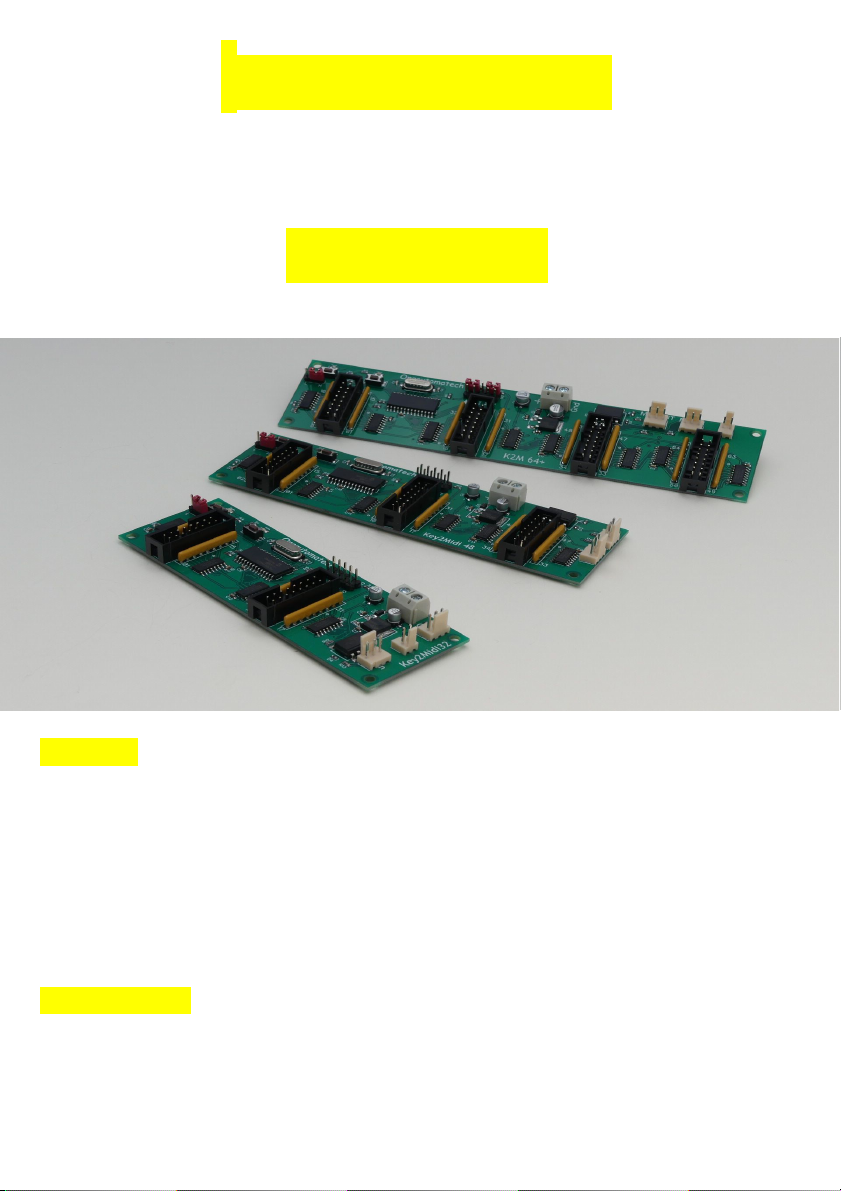
•1. Link your computer out to the K2M board Midi in. Do not plug
anything in the board Midi Out socket.
•2. Switch on the board
•3.In the software Parametor, fill the bo es with the notes you want
regarding of e it numbers.
4. select "64 outputs" (or 32 for K2M 32) and "setting"
5. Press "Send "
The green LED on the card will shut down, the red LED will light up
briefly, then the green LED is on again, it's done. All in less than a
second!
Please note than, even you want to change only a few notes, you have to send
all the notes, alway select the number of notes corresponding to your board.
Parametor allows you to save your scale, so, you'll haven't to tape all the note
numbers in the cases ne t time.
You can save your scale, so, you'll not have to re-tape the number ne t time.
While you are in Parametor, you can also change the velocity value of sent
notes.
You can also program a latency time, (rebounce), depending on your contacts
quality.

Functioning
A few tenths of second after switching on the board, the green LED lights
signifying that the board is ready to work.
Key2Midi works on only one channel at a time, but sends via MIDI OUT all
notes coming in via MIDI IN . So you can connect another board (daisy
chain) .
When applying a voltage over 3 volt (5.5 volt ma ) at an iput, the board
sends a Midi “note on” message , of the number attribuated to this input, and
sends a Midi “note off” message when this tension stops.
Sent note velocity value default is 100.
If you set a latency value for input, the board will wait for the set time to send
the note. This latency can be set with Parametor (0 up to 127 ms). The feature
is useful when scanning an organ roll with some “bridges” on notes.
If you push the channel button, an “all note off” message is sent on all the 16
channels.
Guarantee
The Key2Midi as all the Orgautomatech boards has a one-year guaranty
against manufacturing fault. Each board is tested before shipping. I advice
you to try it with its factory settings before changing the note mapping.
Trouble shooting:
If there seems to be a problem, please check a few things before sending back
the board:
The green LED doesn't light after switching on the board:
• Check the power polarity
The green LED lights, but no sound is coming out my sound module:
•Is the midi cable connected to the board’s MIDI OUT and in the
sound module MIDI IN? Don't laugh, this happens also to me...
•The MIDI IN is used to connect another board. It must not be

connected to the MIDI OUT of the computer or MIDI THRU of the
sound module!
•Is the board midi receiving channel the same as the channel being
sent?
Don't forget: the power supply must be a regulated DC.
Orgautomatech
Christian Blanchard
113 rue Champommier
79000 Niort
FRANCE
33(0)6 40 88 11 95
chris@orgautomatech,fr
www,orgautomatech,fr
SIRET 399 479 138 00022
Mise à jour le 18/12/20
Table of contents