Oricom MX1100G User manual

1
MX1100G
VHF MARINE RADIO
• Ingress protected to IPX7*
• Independent Class B DSC Dedicated Receiver
• Speaker Vibration Draining Function
• Built-in GPS Receiving Module
* The MX1100G meets IPX7 standard.
This is capable of withstanding water immersion of
up to 1m for 30 minutes.
INSTRUCTION MANUAL

Need Help?
If you need assistance setting up or using your Oricom product now or in the future,
call Oricom Support Australia on:
(02) 4574 8888
www.oricom.com.au
Mon-Fri 8am – 6pm AEST
New Zealand
0800 67 42 66
Mon-Fri 10am – 8pm NZST
Thank you for purchasing this Oricom VHF Marine Radio.
Please ensure you read this user guide carefully before using the MX1100G Radio
to ensure you familiarise yourself with the functions and operation.
PLEASE RETAIN THE USER GUIDE FOR FUTURE REFERENCE.
Compliance
The MX1100G complies with the Australian Communications and Media Authority
Radiocommunications VHF Radio Telephone Equipment - Maritime Mobile Service
Standard 2018 when assessed and tested in accordance with ETSI EN 301 025
V2.2.1 (2017-03).
OPERATING RULES
Priorities
Read all rules and regulations relating to priorities and keep an up-to-date copy.
Safety and distress calls take priority over all other calls.
You must always monitor Channel 16 when you are not operating on another chan-
nel.
False or fraudulent distress calls are prohibited by law.
Privacy
Information overheard but not intended for you cannot be used in any way by law.
Offensive or disrespectful language is prohibited.
RADIO LICENCES
Ship Station License
VHF Marine Radios inAustralia are covered by a Class License. For more information,
visit: https://www.acma.gov.au/Citizen/TV-Radio/Radio/Marine-and-Amateur-Radio/
marine-vhf-radio-1
Operators License
For information on using this product in Australia. visit the ACMA website below:
https://www.acma.gov.au/theacma/marine-vhf-radio
RANGE
The range of VHF transmissions depends on antenna height, transmitter power and
the terrain over which the signals pass.
DIGITAL SELECTIVE CALLING (DSC)
The Digital Selective Calling (DSC) feature on your MX1100G Marine VHF radio
uses an arranged digital data message, instead of voice, in order to transmit urgent
or important information to another radio.
DSC is designed to alert all radios within a predetermined range to a distress mes-
sage, even if the vessel’s listening watch is not being maintained, as this increases
the chance of the signal being heard.

Thank you for purchasing this VHF DSC marine radio. Please read all instructions
carefully and completely before using the radio.
The radio is based on the technical characteristics of CCIR 493-4 and the opera-
tional characteristics of CCIR 541-3 of the International Radio Consultative Com-
mittee, and the resolutions of the International Telecommunication Union ITU-R
RecommendationA.803(19), complying with national regulations and combined with
practical use, a versatile Class B VHF DSC marine radio, it has a dedicated DSC
receiving channel.
This radio adopts advanced waterproof technology and has excellent waterproof
performance.
PLEASE NOTE: this radio requires a MMSI number to use the DSC functions.
It will prompt you to enter the number each time the radio is turned on until you enter
your MMSI number.
Bypass entry of the MMSI by pressing the BACK button please see page 14 for MMSI
code programming.
WARNING
• When transmitting, keep your body or head more than 20cm from
the antenna.
• DO NOT transmit near electrical blasting equipment, or in explosive
atmospheres.
• DO NOT allow children to operate a radio transmitter unsupervised.
CAUTION
• Only use the DISTRESS call when your ship, or a person on the
vessel is in an emergency.
• Avoid installation in direct sunlight or high heat, humidity and dust.
• The working voltage for the radio is 13.8V. If the power source is
24V, ensure a power converter (24V convert to 13.8V) is used,
otherwise the radio will not work.
• Never directly connect to 230V AC, as this will damage the radio. If
an abnormal odor or smoke is detected from the radio, turn off the
power immediately.
• Do not transmit before connecting the antenna, as this will damage
the radio.
• During extended periods of use, it is normal for the radio housing
to become warm.
i

CONTENTS
PREPARATION
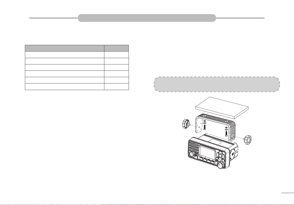
Supplied Accessories............................................................................................1
Radio Mounting.....................................................................................................1
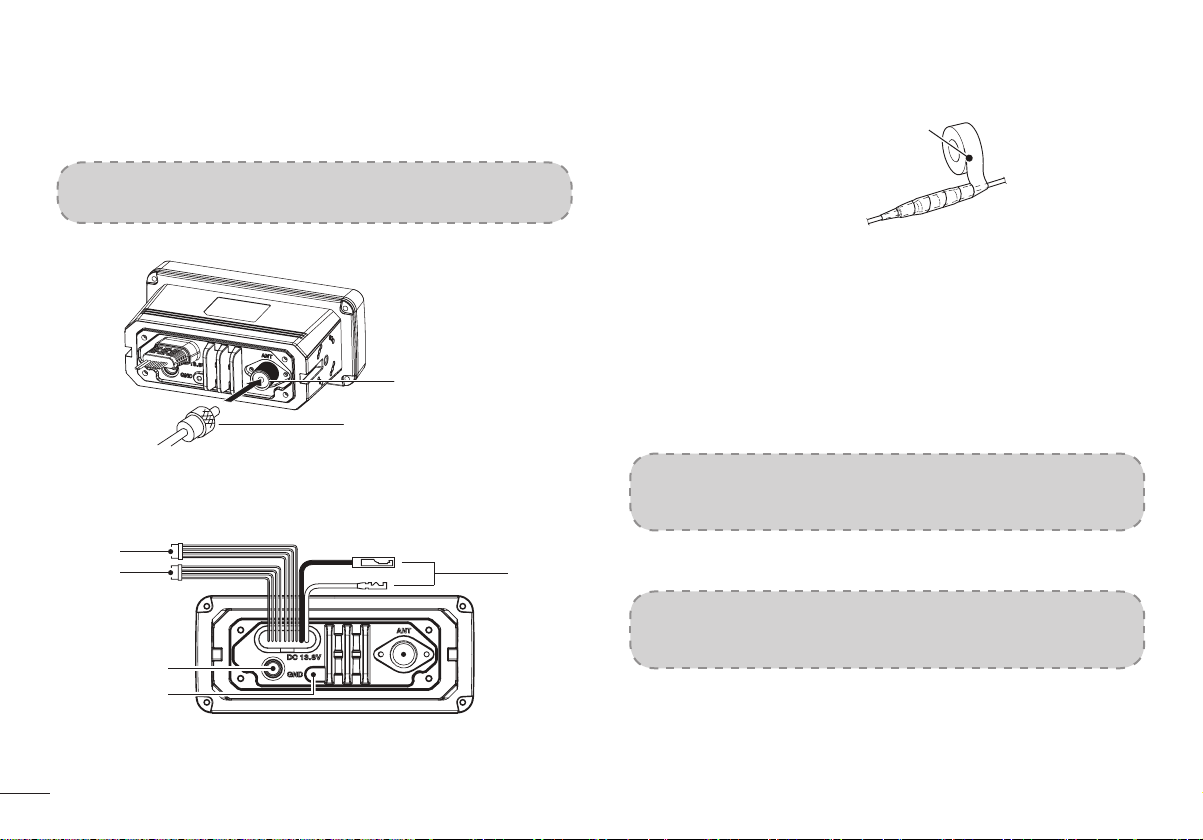
Antenna Connection.............................................................................................2
Installation of Connecting Cables.........................................................................2
Dimensions...........................................................................................................3
PANEL DESCRIPTION
Front Panel ..........................................................................................................4
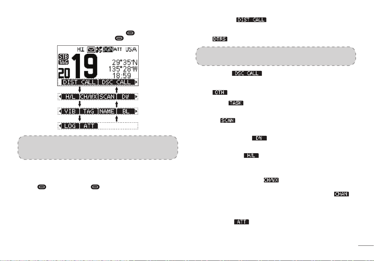
Softkeys ...............................................................................................................5
Microphone...........................................................................................................6
Function Display...................................................................................................6
BASIC OPERATION
Power ON/OFF.....................................................................................................8
Transmitting and Receiving ..................................................................................8
Channel Group Selection......................................................................................9
Channel Selection ................................................................................................9
Call Channel Programming.................................................................................10
Channel Name....................................................................................................10
Display Backlight ................................................................................................10
Display Contrast ................................................................................................. 11
Vibration Water Draining Function...................................................................... 11
Microphone Lock Function.................................................................................. 11
SCAN OPERATION
Scan Types.........................................................................................................12
Setting TAG Channels ........................................................................................12
Starting a Scan...................................................................................................12
DUALWATCH / TRI-WATCH
Description..........................................................................................................13
Operation............................................................................................................13
DSC OPERATION
MMSI Code Programming .................................................................................14
ATIS ID Programming ........................................................................................14
DSC Address ID .................................................................................................15
Distress Call .......................................................................................................18
Individual Call .....................................................................................................21
Group Call...........................................................................................................24
All Ships Call.......................................................................................................25
Position Request Call / Polling Request Call .....................................................26
Test Call .............................................................................................................29
DSC Log ............................................................................................................32
Multiple-task Mode .............................................................................................32
MENU SCREEN OPERATION
Menu Screen Operation......................................................................................35
Menu Screen Items ............................................................................................35
Radio Settings ...................................................................................................36
Conguration .....................................................................................................37
VHF MARINE RADIO CHANNEL LIST (Default International)
SPECIFICATIONS
TROUBLESHOOTING
ii

1
PREPARATION
■■Supplied Accessories
The following accessories are supplied:
ITEM QTY
DC Power Cable 1
Spare Fuse 1
Mounting Bracket 1
Mounting Screws Package 1
Instruction Manual 1
GPS Antenna 1
■■Radio Mounting
■◆Using the Supplied Mounting Bracket
The universal mounting bracket supplied with your radio allows overhead or dash-
board mounting.
1. Fix the mounting bracket to overhead or dashboard with the supplied screws
and mount the radio to the mounting bracket with the knob bolts.
2. Adjust the radio so that the face of the radio is at 90°to your line of sight when
operating it and tighten the knob bolts so that the radio is securely mounted.
NOTE: You may use a spongy cushion between the trans-ceiver and mounting
bracket to reduce the impact of vibration.

2
■■Antenna Connection
Please connect an antenna before transmitting. Make sure you are using a good
quality VHF antenna, Connect the antenna cable to the rear antenna socket using a
PL259 coaxial connector with natural impedance 50Ω.
NOTE: Do not transmit without an antenna connected as this will damage the
radio.
To the Antenna
Antenna Connector
Feeder Connector
■■Installation of Connecting Cables
When connecting the external speaker, GPS, DC power supply, computer and nav-
igation device by the rear panel cable end, cover the connectors and cables with
rubber vulcanzing tape as below, to prevent water seeping into the radio.
Rubber Vulcanzing Tape
1.■ External Speaker and Programming Data Leads
• Connect an external speaker to Blue and Black Lead. Blue→Positive Elec-
trode (+), Black→Negative Electrode (-).
• Connect programming cable to Orange and Grey Lead.
2.■ NMEA/Out Leads
Through the rear panel lead, this radio can connect output GPS signals to
other devices.
•■Output Connection: Connect the output to the navigation device input line
(port) that supports NMEA0183 for receiving location data from other ships,
connect as follows: Brown→Sending Data, Data Output (-); White→Sending
Data, Data Output (+).
NOTE: The output signal of this radio complies with NMEA0183 version 2.0
or above, compatible with DSC, DSE navigation equipment, statement format
RMC, GSA, GSV.
3.■ External GPS Antenna
Connect to an external GPS antenna.
NOTE: Make sure that the GPS antenna is installed in an open, unobstructed
position so that the satellite signal can be received well. When installing the
GPS antenna, use the supplied double-sided tape to x it.
4.■ Ground Terminal
Connect this terminal to a vessel ground to prevent electrical shocks and in-
terference from other equipment. Use a PH M3×6 mm screw (not supplied).

3
5.■ DC Power Connector
Red - Positive(+), Black - Negative(-).The output voltage of the connected DC
power supply must be 13.8V, do not connect the radio to a 24V storage power
supply. If the current supplied to the radio is insufcient, the display may darken
during transmission or the transmitting output power may drop signicantly.
NOTE: Connect the DC power cable to a 13.8V DC power supply. Note: make
sure the correct polarity is observed, connect red cable to positive (+) and black
cable to negative (-) terminals.
■◆Fuse Replacement
One fuse is installed in the supplied DC power cable. If a fuse blows or the radio
stops functioning, track down the source of the problem rst, then replace the
damaged fuse with a new, rated one.
NOTE: Please power off radio before replacing the fuse, the required fuse is
DC15A/32V.
■■Dimensions
Unit: mm
155
137
25.5
87.5
98.5
155
65.5
35
51.4
65.5

4
PANEL DESCRIPTION
■■Front Panel
Speaker Display
❶❷ ❸
❹
❺
❻
❼❽❾
❶ Menu Key [MENU]
• Press this key to enter or exit the menu operation display interface.
❷ Enter Key [OK]
• Press this key to set the entered data, selected items, etc.
❸ Left/Right Keys [◄]/[►]
• Press to scroll through the softkey functions.
• Press to select a character or number in input mode.
❹ Up/Down Keys [▲]/[▼]
• Press to select work channel, menu items, menu settings, etc.
• Press to select a character or number in the entry in input mode.
❺ Clear Key [BACK]
• Press to cancel the settings, or exit the DSC menu.
❻ Power/Volume/Squelch Knob [PWR/VOL/SQL]
• Press and hold for one second to power ON/OFF the radio.
• Rotate or press to enter the volume setting display interface, then rotate to
adjust the volume.
• Press twice to enter the squelch level setting display interface, then rotate to
adjust the squelch.
• In the menu interface, rotate to select menu items.
• In input mode, press to select a character or number, and rotate to move
the cursor.
❼ Channel 16 / Call Channel Key [16/C]
• Press to select Channel 16.
• Press and hold for one second to select Call Channel (Default Channel 9).
• “ ” appears when the Call channel is selected.
❽ Softkeys [ ]
• Press [◄] or [►] to scroll through the key functions at the bottom of the dis-
play, then press the 4 softkeys [ ] to select the key function.
• The denition of the softkeys is described in the following description.
❾ Distress Key [DISTRESS]
• Open the cover, press and hold this key for 3 seconds to transmit a Distress
call.

5
■■Softkeys
Frequently used functions are assigned to the softkeys [ ] for easy access. The
functions’ icons are displayed above the softkeys [ ], as shown below.
Push [B]Push [A]
Push [B]Push [A]
Push [B]Push [A]
NOTE: The displayed icons or their order may differ depending on software
version. When the MMSI code is not set, the softkeys for DSC function are not
displayed.
■◆Using the Softkeys
Press [◄] or [►] to scroll through the selectable functions that are assigned to the
softkeys [ ]. Press the softkeys [ ] under the functions’s icon to select the
function.
■◆Softkey Functions
The softkey functions that can be implemented are as follows:
1.■ Distress Call [ ]
Press to display the “DISTRESS” screen, to select the Nature of distress, then
to make a call.
• “ ” is displayed.
NOTE: NEVER make a distress call if your ship or a person is not in an emer-
gency. A distress call should be made only when immediate help is needed.
2.■ Other DSC [ ]
Press to select DSC CALL, including Individual Call, Group Call,All Ships Call,
Test Call.
• “ ” is displayed.
3.■ Task List [ ]
Press to display Task List.
4.■ Scan [ ]
Press to start or stop Normal Scan or Priority Scan.
5.■ Dualwatch/Tri-watch [ ]
Press to start or stop Dualwatch/Tri-watch.
6.■ High/Low Power [ ]
Press to set output power to high or low.
• Some channels are set to low power only.
7.■ Channel/Weather Channel [ ]
Press to select regular channels or Weather Channel.
• The Weather Channel is for USA and Australian versions only. “ ” is
displayed for other versions.
• While the Call channel or Channel 16 is displayed, press this key to return to
regular channel mode.
8.■ Attenuation [ ]
Press to turn the Attenuator ON or OFF.

6
9.■ Vibration Water Draining [ ]
Press and hold this key to turn ON Vibration Water Draining function to clear
water from the speaker grill.
10. Favourite Channel [ ]
Press to set or release the displayed channel as a Favourite Channel.
• Press to set current untagged channel as TAG channel;
Press again to clear the TAG channel.
11. Channel Name [ ]
Press to edit the name of the displayed channel.
12. Backlight [ ]
Press to enter display and keypad backlight brightness adjustment mode,
press [◄]/[►], [▲]/[▼] keys or rotate [DAIL] knob to adjust display and key-
pad backlight brightness.
• 8 levels of backlight brightness: 1~7, OFF.
13. Log [ ]
Press to display received call log or distress message log.
■■Microphone
Microphone
❶
❷❹
❸
❶ PTT Switch [PTT]
• Press and hold to transmit; Release to receive.
❷ Transmit Power Key [H/L]
• Press to select high or low output power.
Some channels are set to low power only.
• While pressing and holding [H/L], power ON to toggle the microphone lock
function ON or OFF.
❸ Channel [▲][▼] Keys
• Press to select operating channel, Set mode setting etc.
• When the favourite channel function is activated, press [▲]/[▼] keys to se-
lect the favourite channels in the selected channel group in sequence.
❹ Channel 16 / Call Channel Key [16/C]
• Press to select Channel 16.
• Press and hold for one second to select Call Channel (Default Channel 9).
“ ” appears when the Call channel is selected.

7
■■Function Display
❶❽
❼
❻
❿⓫ ❾⓬⓭⓮⓯
❷
❸
❹
❺
No. Name Descriptions
1 Signal Status
Indicator • “ ” displayed while receiving.
• “ ” displayed while transmitting.
2 Status Indicator • “ ” displayed when in the standby mode.
• “ ” displayed when the channel is changed while
receiving or transmitting a signal.
3 Favourite
Channel Icon • “ ” displayed when the Favourite channel is
selected.
4 Operating
Channel
Number
• Displays the selected operating channel number, can
display 4 digits channel number.
• “A” or “B” is displayed when a simplex channel is
selected.
5 Softkeys
Function Display • The functions of softkeys are displayed.
6 Position/Time
Readouts • Readouts the current position and time when valid
GPS data is received or when manually input.
• “NO POS NO TIME” is displayed if no GPS data
has been received, and then a warning message is
displayed for 2 minutes after turning ON the radio.
• “??” blinks if no GPS data is received for 30 seconds
after receving valid GPS data, and then “??” and a
warning message are displayed after 10 minutes.
• A warning message is displayed if no GPS data is
received for 4 hours after receiving valid GPS data.
• A manually input GPS data is valid for 23.5 hours,
and then a warning message is displayed.
7 Scan Indicator • “SCAN 16” is displayed while Priority Scan, “SCAN”
is displayed while Normal Scan.
• “DW 16” is displayed while Dualwatch, “TW 16” is
displayed while Tri-watch.
8 Channel Group
Indicator • “USA” is displayed when USA channel group is
selected.
• “INT” is displayed when International channel group
is selected.
• “CAN” is displayed when Canada channel group is
selected.
• “WX” is displayed when Weather channel group is
selected.
When the WX-Alert is set to ON, “ ” is
displayed instead of “WX”.
9 Attenuator Icon • “ ” is displayed when RF attenuation is ON.
10 Duplex Channel
Indicator • “ ” is displayed when a Duplex channel is
selected.
11 GPS Status Icon •■GP: GPS; GN: GPS+GLONASS;
DGP: SBAS+GPS;
DGN: SBAS+GPS+GLONASS
12 Call Channel
Indicator • “ ” is displayed when a Call channel is selected.
13 GPS Positioning
Icon • Displayed when valid GPS position data (Including
GPS and GLONASS) is received.
• Blinks when received GPS position data is invalid.
14 Message Icon • “ ” is blinked when there is an unread DSC
message, “ ” disappears when the message has
been read.
15 Output Power
Icon • “HI” is displayed when high power is selected.
• “LOW” is displayed when low power is selected.

8
CONTENTSBASIC OPERATION
■■Power ON/OFF
1. Press and hold [PWR] knob for 1 second to power ON.
2. Press and hold [PWR] knob for 1 second again to power OFF.
■■Transmitting and Receiving
■◆Transmitting
1. Press [H/L] key on the microphone to select the output power if necessary.
• “LOW” appears when low power is selected.
• Choose low power for short range communication, choose high power for
longer distance communication.
• Some channels are low power only.
2. Press and hold [PTT] key to transmit, then speak into the microphone.
• “ ” appears.
• CH70 is for DSC transmitting only.
3. Release [PTT] to receive.
NOTE: Do not transmit without an Antenna as this will damage the radio.
If the TOT function is enabled by the PC programming software, the transmis-
sion time-limited protection function prohibits continuous transmission for a long
time.
■◆Receiving
Volume Adjustment:
1. Rotate [VOL] knob to adjust the volume, volume adjustment interface is dis-
played.
2. If no key is pressed within 5 seconds, the interface will automatically exit.
Squelch Level Adjustment:
1. Press [SQL] knob twice, squelch level adjustment interface is displayed.
2. Rotate [SQL] knob to adjust the squelch level.
3. If no key is pressed within 5 seconds, the interface will automatically exit.

9
■■Channel Group Selection
Channel Groups are pre-programmed.
1. Press [MENU] key, the menu interface is displayed.
2. Press [▲]/[▼] or rotate [DIAL] knob to select “Radio Settings”, then press
[OK], the “RADIO SETTINGS” screen is displayed.
3. Press [▲]/[▼] or rotate [DIAL] knob to select “Channel Group”, then press
[OK], the “CHANNEL GROUP” screen is displayed.
4. Press [▲]/[▼] or rotate [DIAL] knob to select a Channel Group, then press
[OK], the selected Channel Group Icon is displayed on the operating screen.
Press [ ] to exit the menu screen.
■■Channel Selection
■◆Regular Channel
Press [▲]/[▼] to select regular channel.
■◆Channel 16
Channel 16 is the distress and safety channel. It is used for establishing initial con-
tact with a station and for emergency communications. Channel 16 is monitored
during both Dualwatch and Tri-watch.
1. Press [16/C] to select Channel 16.
2. Press [◄]/[►] to display [ ], then press the softkey below [ ], to
return to the previously selected channel.
■◆Call Channel
Each regular channel group has a separate leisure-use Call channel (Default
Channel 9). The Call channel is monitored during Tri-watch.
1. Press and hold [16/C] for 1 second to select the Call channel of the selected
channel group. “ ” and Call channel number appear.
2. Press [◄]/[►] to display [ ], then press the softkey below [ ], to
return to the previously selected channel. Press [▲] or [▼] to select channel.
■◆Weather Channels
The radio has 10 weather channels.
The radio can automatically detect a weather alert tone on the selected weather
channel while receiving on a regular channel or while scanning.
Selecting a Weather Channel
1. Press softkey [ ] to select between weather channel and regualr
channel.
• “WX” appears when a weather channel is selected.
• When the WX-Alert is set to ON, “ ” is displayed instead of “WX”.
2. Press [▲]/[▼] to select a Weather channel.

10
Setting the Weather Alert
1. Press [MENU] key, the menu interface is displayed.
2. Press [▲]/[▼] or rotate [DIAL] knob to select “Radio Settings”, then press
[OK], the “RADIO SETTINGS” screen is displayed.
3. Press [▲]/[▼] or rotate [DIAL] knob to select “WX Alert”, then press [OK], the
“WX ALERT” screen is displayed.
4. Select “On With Scan” or “On”, “ ” is displayed on screen.
■■Call Channel Programming
Call channel is used to select Channel 9 (default), however, you can program the Call
channel with your most offer-used channel in each channel group for quick recall.
1. Press [MENU] key, the menu interface is displayed.
2. Press [▲]/[▼] or rotate [DIAL] knob to select “Radio Settings”, then press
[OK], the “RADIO SETTINGS” screen is displayed.
3. Press [▲]/[▼] or rotate [DIAL] knob to select “Call Channel”, then press [OK],
the “CALL CHANNEL” screen is displayed.
4. Press [▲]/[▼] or rotate [DIAL] knob to select the desired Call channel.
5. Press [OK] to conrm, the selected channel is set as Call channel.
6. Press softkey [ ] to cancel and exit.
■■Channel Name
Each channel can be assigned a name of up to 10 characters. Characters available
for input: 26 uppercase letters, number 0~9, symbol (! “ # $ % &’()* +,-° / [\]^ _:;< =
> ?), SPACE.
1. Press [▲]/[▼] to select the channel you want to edit.
• Before setting, you should exit Dualwatch, Tri-watch or scan.
2. Press [◄]/[►] to display [ ].
3. Press softkey [ ], the “CHAN NAME” screen is displayed.
4. Select [ ] to input symbols, and select [ ] to input numbers
and letters.
5. Press [▲]/[▼]\[◄]/[►] to select characters or space.
6. Press [OK] to input the selected character.
7. Select “←” or “→”, or rotate [DIAL] to move the cursor.
8. Repeat steps 4~7 to input all the characters.
9. Press softkey [ ] to cancel editing.
10. Press softkey [ ] to save the edited name and return to the operating
screen.
■■Display Backlight
Backlight brightness of the LCD display and keypads can be set by this function,
totally 7 levels of brightness and OFF optional.
1. Press [MENU] key, the menu interface is displayed.
2. Press [▲]/[▼] or rotate [DIAL] knob to select “Conguration”, then press [OK],
the “CONFIGURATION” screen is displayed.
3. Press [▲]/[▼] or rotate [DIAL] knob to select “Backlight”, then press [OK], the
“BACKLIGHT” screen is displayed.

11
4. Press [▲]/[▼] or rotate [DIAL] knob to adjust the backlight brightness.
5. Press [OK] to conrm.
• Press softkey [ ] to return to main interface.
■■Display Contrast
LCD display contrast can be set by this function, Level 1 to 8.
1. Press [MENU] key, the menu interface is displayed.
2. Press [▲]/[▼] or rotate [DIAL] knob to select “Conguration”, then press [OK],
the “CONFIGURATION” screen is displayed.
3. Press [▲]/[▼] or rotate [DIAL] knob to select “Display Contrast”, then press
[OK], the “CONTRAST” screen is displayed.
4. Press [▲]/[▼] or rotate [DIAL] knob to adjust the display contrast.
5. Press [OK] to conrm.
• Press softkey [ ] to return to main interface.
■■Vibration Water Draining Function
Vibration helps drain water away from the speaker housing (water that might other-
wise mufe the sound coming from the speaker). The radio makes a vibrating noise
when this function is being used.
NOTE: Do not use the vibration water draining function when connecting an
external speaker.
1. Press [◄]/[►] to display [ ].
• “VIB WATER” interface is displayed.
2. Press and hold softkey [ ],the radio emits a low sound for draining.
3. Release softkey [ ] to turn vibration water draining function OFF.
■■Microphone Lock Function
The microphone lock function electrically locks all keys except for [PTT] on the sup-
plied microphone. This prevents accidental channel changes and function access.
1. Press and hold [DIAL] knob for one second to power OFF.
2. While pressing and holding [H/L] on the microphone, power ON to toggle the
microphone lock function ON or OFF.
[H/L]

12
SCAN OPERATION
■■Scan Types
This radio has normal scan and priority scan, this can be set in the menu item under
“Radio Settings”.
When the weather alert function is turned ON, the previously selected (last used)
weather channel is also scanned.
Set the TAG channels (scanned channels) before scanning.
Clear the TAG channels which you would like to scanning.
Normal Scan: Normal scan searches through all TAG channels in sequence. Chan-
nel 16 is not checked unless Channel 16 is set as a TAG channel.
Priority Scan: Priority scan searches through all TAG channels in sequence while
monitoring Channel 16.
Priority ScanNormal Scan
). ). ).
). ). ).
). ).
).
).
).
). ).
■■Setting TAG Channels
For more efcient scanning, you can add desired channels as TAG channels or clear
the TAG for unwanted channels.
Channels that are not tagged will be skipped during scanning.
■◆Setting / Clearing a Single Tagged Channel
1. Press [▲]/[▼] to select the channel you want to set as TAG channel.
2. Press [◄]/[►] to display [ ].
3. Press softkey [ ] to set current channel as TAG channel.
• “ ” is displayed on screen.
4. To cancel the TAG channel setting, press softkey [ ] again.
• “ ” disappears from the screen.
■◆Setting / Clearing All Tagged Channels
1. Press [MENU] key, the menu interface is displayed.
2. Press [▲]/[▼] or rotate [DIAL] knob to select “Radio Settings”, then press
[OK], the “RADIO SETTINGS” screen is displayed.
3. Press [▲]/[▼] or rotate [DIAL] knob to select “FAV Settings”, then press [OK],
the “FAV SETTINGS” screen is displayed.
4. Press [▲]/[▼] or rotate [DIAL] knob to select “SetAll Channels” to set all chan-
nels as Tagged Channels.
5. Select “Clear All Channels” to cancel all the TAG channel setting.
6. Select “Set Default” to restore to factory default channel setting.
■■Starting a Scan
Scan Type, Weather Alert, Scan Timer can be set in the menu interface.
1. Press [◄]/[►] to display [ ].
2. Press softkey [ ] to start Normal or Priority Scan.
• “SCAN 16” is displayed during a Priority Scan, and “SCAN” is displayed dur-
ing a Normal Scan.
• When a signal is received, the scan pauses until the signal disappears, or
resumes after 5 seconds, depending on the Scan Timer setting in “Radio
Settings”.
• A beep sounds and “16” blinks when a signal is received on Channel 16
during a Priority Scan.
• Press [▲]/[▼] to change the scanning direction.
3. To stop the scan, press softkey [ ] again.

13
DUALWATCH / TRI-WATCH
■■Description
This radio has Dualwatch and Tri-watch.
Dualwatch monitors Channel 16 while you are receiving on another channel.
Tri-watch monitors Channel 16 and the Call channel while receiving on another channel.
DUALWATCH TRI-WATCH
Call Channel
■■Operation
1. Press softkey [ ] to start Dualwatch or Tri-watch.
• “DW 16” is displalyed during Dualwatch; “TW 16” is displalyed during Tri-
watch.
• A beep tone sounds when a signal is received on Channel 16.
• Tri-watch converts to Dualwatch when a signal is received on Call channel.
2. Press softkey [ ] again to cancel Dualwatch or Triwatch.

14
DSC OPERATION
■■MMSI Code Programming
The 9-digit MMSI (Maritime Mobile Service Identity: DSC self ID) code can be pro-
grammed by PC software and also manually set on this radio.
1. Press and hold [PWR] knob to power ON.
• Three short beeps sound, and “Push [OK] to Register your MMSI” is dis-
played.
2. Press [OK] to start setting the MMSI code.
• During the setup process, press [BACK] to skip the setting and return to
normal operating mode, and you cannot make a DSC call.
3. Enter the MMSI code:
• Press [◄]/[►] to select the desired number.
• Press [OK] to input the selected number.
• Select “←” or “→”, or rotate [DIAL] to move the cursor, then press [OK].
4. Repeat step 3 to enter all 9 digits.
5. After 9 digits have been input, press softkey [ ] to set the code.
6. Enter MMSI code again to conrm.
7. Repeat step 3 to 5 as above.
• When your MMSI code input is successful, “MMSI Successfully Registered”
is displayed as below.
• Once setup is complete the radio can now perform normal operation.
NOTE: In the menu interface, you can query the set MMSI code.
■■ATIS ID Programming
The Automatic Transmitter Identication System (ATIS) ID consists of 10 digits. You
can enter the ATIS ID in the “ATIS ID Input” item on the Menu screen.
Entering the ATIS ID can only be done once via the radio, once entered it can only
be changed via PC programming software.
1. Press [MENU] key, the menu interface is displayed.
2. Press [▲]/[▼] or rotate [DIAL] knob to select “ATIS Setting”, then select “ATIS
ID Input”, then press [OK], the “ATIS ID Input” screen is displayed.
3. Enter the ATIS ID:
• Press [◄]/[►] to select the desired number.
• Press [OK] to input the selected number.
• Select “←” or “→” to move the cursor, then press [OK].

15
4. Repeat step 3 to enter all 10 digits.
5. After 10 digits have been entered, press softkey [ ] to set the ID.
6. Enter ATIS ID again to conrm.
7. Repeat step 3 to 5 as above.
• Once setup is complete the radio can now perform normal operation.
NOTE: In the menu item “Radio Info”, you can query the set ATIS ID.
■■DSC Address ID
Before using the DSC call related function, the DSC can be set as follows:
1. Press [MENU] key, the menu interface is displayed.
2. Press [▲]/[▼] or rotate [DIAL] knob to select “DSC Settings”.
3. Press [OK], the “DSC SETTINGS” screen is displayed.
4. Press [▲]/[▼] or rotate [DIAL] knob to select the submenu item you want to
set up.
• The setting items includes Position Input, Individual ID, Gourp ID,AutoACK,
CH Auto SW, Data Output, Alarm Status, CH 70 SQL Level, Self-Test, Mul-
ti-Task.
5. Press [OK] to enter next level menu.
6. Press [BACK] or softkey [ ] to return to the previous menu. Press
softkey [ ] to return to main interface.
■◆Entering the Position and Time
A Distress call should include the vessel’s position and time. If no GPS data is re-
ceived, manually input the position and Universal Time Coordinated (UTC) time.
• The manual entry is disabled while valid GPS data is received.
• The manually entered position and time is valid only for 23.5 hours, or until turning
OFF the radio.
1. Display the “POSITION INPUT” screen.
2. Press [▲]/[▼]/[◄]/[►] to enter longitude and latitude.
• Press [◄]/[►] to select desired number.
• Press [OK] to enter.
• Select ”←” or “→”, or rotate [DIAL] to move the cursor, then press [OK].
• Move cursor to “N” or “S” to select N (North Latitude) or S (South Latitude).
• Move cursor to “W” or “E” to select W (West Longitude) or E (East Longitude).
3. After position is entered, press [OK] to conrm.
4. In the UTC time editing interface, enter the UTC time as follows.
• Press [◄]/[►] to select desired number.
• Press [OK] to enter.
• Select ”←” or “→”, or rotate [DIAL] to move the cursor, then press [OK].
5. Press softkey [ ] to conrm position and time setting.
6. Press softkey [ ] to return to standby interface.
• The entered position and time are displayed on the operating screen.

16
■◆Entering an Individual ID
You can enter a total of 60 Individual IDs, and assign names to them of up to 10
characters.
1. Display the “INDIVIDUAL ID” screen.
• “NO ID” is displayed if no ID is entered.
2. Press softkey [ ], “INDIVIDUAL ID” entry screen is displayed.
3. Enter an Individual ID:
• Press [◄]/[►] to select the desired number.
• Press [OK] to input the selected number.
• Select “←” or “→” to move the cursor, then press [OK].
✳ The rst digit is xed as “0” for a Group ID.
✳ The rst two digits are xed as “0” for any coast station ID.
4. Repeat step 3 to enter all 9 digits.
5. Then press softkey [ ] to start entering the name.
6. Enter an Individual ID Name:
• Press [▲]/[▼]/[◄]/[►] to select the desired characters.
• Press [OK] to input the characters.
• Select “←” or “→” to move the cursor, then press [OK].
• Press [ ]/[ ]/[ ] to select numbers, characters and
letters.
7. Then press softkey [ ] to save, and return to the previous screen.
• The entered Individual ID name is displayed.
■◆Entering a Group ID
You can enter a total of 30 Group IDs, and assign names to them of up to 10 char-
acters.
1. Display the “GPURP ID” screen.
• “NO ID” is displayed if no ID is entered.
2. Press softkey [ ], “GROUP ID” entry screen is displayed.
3. Enter an Group ID:
• Press [◄]/[►] to select the desired number.
• Press [OK] to input the selected number.
• Select “←” or “→” to move the cursor, then press [OK].
✳ The rst digit is xed as “0” for a Group ID.
✳ The rst two digits are xed as “0” for any coast station ID.
4. Repeat step 3 to enter all 9 digits.
5. Then press softkey [ ] to start entering the name.
Table of contents
Other Oricom Marine Radio manuals
Popular Marine Radio manuals by other brands

NorthStar
NorthStar EXPLORER 725 Dimensions

Uniden
Uniden OSEANUS DSC owner's manual

UPS Aviation Technologies
UPS Aviation Technologies Apollo SL70R installation manual

Garmin
Garmin VHF 315 Series installation instructions

Uniden
Uniden Oceanus LTD1025 owner's manual

Uniden
Uniden Atlantis 150 owner's manual