Oriental motor Alpha STEP SPR Series User manual

HL-0178
Motorized Slider
SPR Series
Single-phase 100−115 V input
Single-phase 200−230 V input
Operating Manual
Thank you for purchasing an Oriental Motor product.
This operating manual describes the product’s handling procedures and safety precautions.
• Please read it thoroughly to ensure safe operation.
• Always keep the manual nearby for immediate reference.

-2-
• Unauthorized reproduction or copying of all or part of this manual is prohibited.
If a new copy is required to replace an original manual that has been damaged or lost, please contact your
nearest Oriental Motor branch or sales office.
• Oriental Motor shall not be liable whatsoever for any problems relating to industrial property rights arising
from use of any information, circuit, equipment or device provided or referenced in this manual.
• Characteristics, specifications and dimensions are subject to change without notice.
• While we make every effort to offer accurate information in the manual, we welcome your input. Should
you find unclear descriptions, errors or omissions, please contact the nearest office.
• is a trademark of Oriental Motor Co., Ltd.
is a trademark of Oriental Motor Co., Ltd., and is registered in Japan and other countries.
Other product names and company names mentioned in this manual may be trademarks or registered
trademarks of their respective companies and are hereby acknowledged. The third-party products
mentioned in this manual are recommended products, and references to their names shall not be construed
as any form of performance guarantee. Oriental Motor is not liable whatsoever for the performance of these
third-party products.
© Copyright ORIENTAL MOTOR CO., LTD. 2004

Table of Contents
-3-
1 Introduction......................................4
1.1 Before Using the Product ..................... 4
1.2 Over View of the Product ..................... 4
1.3 System Configuration........................... 5
2 Safety Precautions........................... 6
3 Preparation ....................................... 8
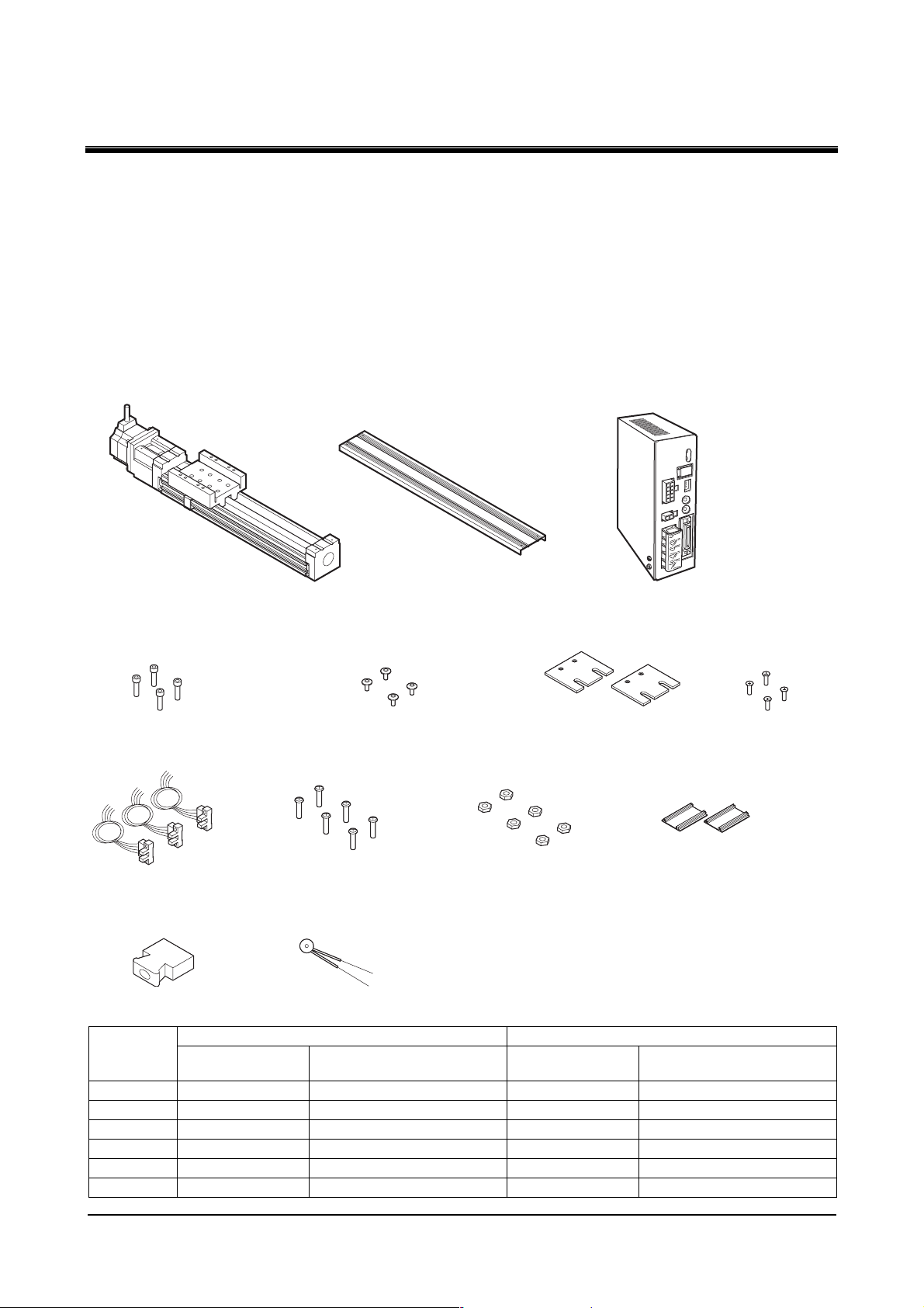
3.1 Checking the Product........................... 8
3.2 Product Number Code ......................... 9
3.3 Motorized Slider and Driver
Combinations ....................................... 9
3.4 Names of the Parts and
Main Functions ................................... 10
4 Installation ...................................... 12
4.1 Location for Installation ...................... 12
4.2 Motorized Slider Installation ............... 12
4.3 Installing the Load .............................. 17
4.4 Install the Driver ................................. 18
5 Connections ................................... 21
5.1 Connection Example for a
Standard Type .................................... 21
5.2 Connection Example for an
Electromagnetic Brake Type .............. 24
5.3 Connecting to the Power supply ........ 26
5.4 Grounding the Motorized Slider
and Driver........................................... 27
5.5 Noise Elimination Measure ................ 27
5.6 Connecting the Electromagunetic
Brake .................................................. 28
5.7 Connecting Control Input/Output........ 29
5.8 Input Signals....................................... 30
5.9 Output Signals.................................... 33
5.10 Connecting the Photosensor .............. 35
5.11 Timing Chart ....................................... 36
6 Setting.............................................37
6.1 Resolution Selector Switch................. 37
6.2 Pulse-Input Mode Selector Switch ..... 37
6.3 Current Setting Switch........................ 38
6.4 Speed Filter Setting Switch ................ 39
7 Running ..........................................40
7.1 Return to Mechanical Home
Operation............................................ 40
7.2 Positioning Operation ......................... 40
7.3 Operating the Electromagnetic
Brake Type ......................................... 44
8 Maintenance ...................................46
9 Troubleshooting and Remedial
Actions............................................47
9.1 Protective Functions........................... 47
9.2 Troubleshooting.................................. 48
10 Appendix.........................................49
10.1 Specifications ..................................... 49
10.2 Acceleration Setting Curve................. 53

1 Introduction
-4-
1 Introduction
1.1 Before Using the Product
• Only qualified personnel should work with the product.
• Use the product correctly after thoroughly reading the section “2 Safety Precautions”.
• The product described in this manual has been designed and manufactured for use in general industrial
machinery, and must not be used for any other purpose. Oriental Motor Co., LTD. is not responsible for any
damage caused through failure to observe this warning.
1.2 Over View of the Product
The Motorized Slider SPR series models are unit products consisting of a high performance
micro-stepping driver and a stepping motor ( ) with a built-in rotor position sensor.
The SPR series models incorporating are not subject to missteps, even when the load changes
suddenly. The speed and amount of rotation are constantly monitored during operation. When an overload is
about to cause the motor to misstep, any delay in response is corrected and operation continues at maximum
torque.
In addition to the type equipped with an electromagnetic brake is also available, which is suitable for holding
the table in position during up or down movement in applications involving vertical travel.
Low-speed operation at low vibration levels
The Motorized Slider SPR series achieves smooth, low-speed operation with extremely low
vibration, thanks to micro-stepping drive, which enables stepping at minute angles.
Built-in alarm function
Whenever a load greatly exceeding the Motorized Slider rating is encountered, or when the table is
constrained during operation, the driver outputs a warning alarm.
In a vertical-travel application, the electromagnetic brake may be triggered upon the detection of this alarm to
prevent a moving section or the table from falling.
Selectable resolution
The resolution of the motorized slider can be switched between :
• The basic resolution.
• The ×10 resolution with the ×10 (resolution select) input.
The photosensor’s (accessory) installation positions can be changed
The motorized slider’s mechanical home position and limit positions can be set freely using the three
accessory photosensors.

1 Introduction
-5-
1.3 System Configuration
Controllers with pulse-output functions are needed to operate the Motorized Slider SPR Series.
+LS sensor
Home
sensor
-LS sensor
Driver
Motorized slider
Motor cable
(sold separately)
CN2
CN4
Controller
(programmable controller
or equivalent)
CN4
CN1
CN2
Control input CN3
Positioning controller
XG9200 Series
(sold separately)
Data setting unit
Pulse cable
(sold separately)
Control output
Motorized Slider SPR Series
The
∗ When using the electromagnetic brake type, be sure to use the motor cable (sold separately). The electromagnetic brake
will not work if the motor cable is directly connected to the driver.
Additionally, use a 24 VDC power supply for the electromagnetic brake.

2 Safety Precautions
-6-
2 Safety Precautions
The precautions described below are intended to prevent danger or injury to the user and other personnel
through safe, correct use of the product.
Warning
Handling the product without observing the instructions that accompany “ Warning”
may result in serious bodily injury or death.
Caution
Handling the product without observing the instructions that accompany “Caution”
may result in bodily injury or property damage.
Note The items under this heading contain important handling instructions that the user
should observe to ensure the safe use of the product.
Warning
General
• Do not use the product in explosive or corrosive environments, in the presence of flammable gases,
locations subjected to splashing water, or near combustibles. Doing so may result in fire, electric shock or
injury.
• Assign qualified personnel the task of installing, wiring, operating/controlling and/or inspecting and
troubleshooting the product. Failure to do so may result in fire, electric shock or injury.
• Do not transport, install the product, perform connections or inspections when the power is on. Always turn
the power off before carrying out these operations. Failure to do so may result in electric shock.
• The terminals on the driver’s front panel marked with symbol indicate the presence of high
voltage. Do not touch these terminals while the power is on to avoid the risk of fire or electric shock.
• Provide a means to hold the moving parts in place for applications involving up/down travel. The
motorized slider loses holding ability when the power is shut off, allowing the moving parts to fall and
possibly causing injury or damage to equipment.
• Do not use the motorized slider’s built-in electromagnetic brake mechanism for stopping or safety purposes.
Using it for purposes other than holding the moving parts and motor in position may cause injury or
damage to equipment.
• When the driver-protection function is triggered, the motorized slider will stop and lose its holding ability,
possibly causing injury or damage to equipment.
• When the driver’s protection function is triggered, shut off the power immediately. Turn the power back on
only after removing the cause. Continuing the operation without removing the cause of the problem may
cause malfunction of the motorized slider, leading to injury or damage to equipment.
Installation
• Install the motorized slider and driver in their enclosures in order to prevent electric shock or injury.
• Install the motorized slider so as to avoid contact with hands, or ground it to prevent the risk of electric
shock.
Connection
• Keep the driver’s input-power voltage within the specified range to avoid fire and electric shock.
• Connect the cables securely according to the wiring diagram in order to prevent fire and electric shock.
• Do not tamper with the motor cable, sensor cable, or cable obtained separately. This may result in fire or
electric shock.
• To prevent electric shock, be sure to install the terminal cover (supplied) over the driver’s power-supply
terminals after making connections.

2 Safety Precautions
-7-
Operation
• Turn off the driver power in the event of a power failure, or the motorized slider will suddenly start when
the power is restored and may cause injury or damage to equipment.
• Do not turn the C. OFF (All Windings Off) input to “ON” while the motorized slider is operating. The
motorized slider will stop and lose its holding ability, which may result in injury or damage to equipment.
• If the driver’s OPERATION LED does not come on when the power is turned on, shut off the power
immediately. The neutral-side fuse may be burnt out while the live-side fuse is intact, posing a risk of
electric shock. For repair, contact the sales office from which you purchased the product.
Maintenance and Inspection
• Before working on the system, shut off the power to the driver and wait 10 seconds. Failure to do so may
result in electric shock.
Repair, Disassembly and Modification
• Do not disassemble or modify the motorized slider or driver. Refer all such internal inspections and repairs
to the sales office from which you purchased the product.
Caution
General
• Do not use the motorized slider and driver beyond their specifications, or electric shock, injury or damage
to equipment may result.
• Keep your fingers and objects out of the openings in the motorized slider and driver, or electric shock,
injury or damage to equipment may result.
• Do not touch the motor or driver during operation or immediately after stopping. The surfaces are hot and
may cause a burn.
Transportation
• Do not hold the motorized slider’s table, motor cable or sensor cable. This may cause injury.
Installation
• Keep the area around the motorized slider and driver free of combustible materials in order to prevent fire
or a burn.
• To prevent the risk of damage to equipment, leave nothing around the motorized slider and driver that
would obstruct ventilation.
• Provide a accessory cover on the motorized slider to prevent injury.
• Do not climb on or hang the motorized slider or driver. This may cause injury.
Operation
• Use a motorized slider and driver only in the specified combination. An incorrect combination may cause a
fire.
• To avoid injury, remain alert during operation so that the motorized slider can be stopped immediately in an
emergency.
• Before supplying power to the driver, turn all control inputs to the driver to “OFF”. Otherwise, the
motorized slider may start suddenly and cause injury or damage to equipment.
• To prevent bodily injury, do not touch the table of the motorized slider during operation.
• Before traveling the table of the motorized slider directly with the hands (as in the case of manual
positioning), confirm that the driver C.OFF (All Windings Off) input is “ON” to prevent injury.
• When an abnormality is noted, stop the operation immediately, or fire, electric shock or injury may occur.
Maintenance and Inspection
• To prevent the risk of electric shock, do not touch the terminals while measuring the insulation resistance or
conducting a voltage-resistance test.
Disposal
• When disposing of the motorized slider and driver as ordinary industrial waste.

3 Preparation
-8-
3 Preparation
This section covers the points to be checked, along with the names and functions of respective parts, and the
specifications.
3.1 Checking the Product
Upon opening the package, verify that the items listed below are included. Report any missing or damaged
items to the sales office from which you purchased the product.
Verify the model number of the purchased unit against the number shown on the package label.
Check the model number of the motorized slider and driver against the number shown on the nameplate.
The package models and corresponding motorized slider and driver combinations are listed on P. 9.
•Motorize slider 1 unit
•Motorized slider installation Allen bolts
(See the table below for the supplied
quantity.)
•Driver mounting brackets 2 pcs. •Screws for driver
mounting brackets
4 pcs. (M3)
•Cover installation
countersunk screws 4 pcs.
(M3×5)
•Photosensors 3 pcs.
•Control input/output
connector 1 pcs.
•Varistor 1 pcs.
(only for the electromagnetic brake type)
•Sensor line holder
(See the table below for the supplied
quantity.)
•Sensor installation
pan-head screws 4 pcs. (M3)
•Sensor installation
hex nuts 6 pcs. (M3)
•Cover 1 unit •Driver 1 unit
Items Supplied with Sensor Line Holder(s)
SPR60 SPR86
Stroke Number of sensor
line holder
Number of hexagonal socket
head screw (M5×15)
Number of sensor
line holder
Number of hexagonal socket
head screw (M6×15)
50 mm 1 4 −−
100 mm 1 4 −−
200 mm 2 6 2 6
300 mm 3 8 3 8
400 mm 4 10 4 10
500 mm 5 12 5 12

3 Preparation
-9-
3.2 Product Number Code
SPR 60 B 10 - 1 S M J D
Series name SPR series
Slider width 60: 60 mm
86: 86 mm
Drive method B: Ball screw
Lead 10: 10 mm
Stroke 05: 50 mm 3: 300 mm
1: 100 mm 4: 400 mm
2: 200 mm 5: 500 mm
None: Standard type
M: With electromagnetic brake type
Power input None: Single-phase 100
-
115 V
J: Single-phase 200
-
230 V
Driver accessories
Power unit S: AS series
3.3 Motorized Slider and Driver Combinations
Package model Slider model Driver model Stroke
SPR60B10-05S(M)D SPR60B10-05S(M)50 mm (1.97 inch)
SPR60B10-1S(M)D SPR60B10-1S(M)100 mm (3.93 inch)
SPR60B10-2S(M)D SPR60B10-2S(M)200 mm (7.87 inch)
SPR60B10-3S(M)D SPR60B10-3S(M)300 mm (11.8 inch)
SPR60B10-4S(M)D SPR60B10-4S(M)400 mm (15.7 inch)
SPR60B10-5S(M)D SPR60B10-5S(M)
LDS1B-B
(Single-phase
100−115 V input)
500 mm (19.7 inch)
SPR86B10-2S(M)D SPR86B10-2S(M)200 mm (7.87 inch)
SPR86B10-3S(M)D SPR86B10-3S(M)300 mm (11.8 inch)
SPR86B10-4S(M)D SPR86B10-4S(M)400 mm (15.7 inch)
SPR86B10-5S(M)D SPR86B10-5S(M)
LDS1B-C
(Single-phase
100−115 V input)
500 mm (19.7 inch)
SPR86B10-2S(M)JD SPR86B10-2S(M)J 200 mm (7.87 inch)
SPR86B10-3S(M)JD SPR86B10-3S(M)J 300 mm (11.8 inch)
SPR86B10-4S(M)JD SPR86B10-4S(M)J 400 mm (15.7 inch)
SPR86B10-5S(M)JD SPR86B10-5S(M)J
LDS2B-C
(Single-phase
200−230 V input)
500 mm (19.7 inch)
∗ The strokes assume use of two photosensors (+LS sensor and −LS sensor). Adding a HOME sensor will reduce the
stroke by 10 mm.

3 Preparation
-10-
3.4 Names of the Parts and Main Functions
Motorized Slider
This figure shows the electromagnetic brake type, accessory cover, photosensors, and sensor line holder
installed.
1
8 5 6 7
2 3 4
Name Description
①Power unit Motor used for driving ( AS series stepping motor)
②Table The traveling part of the motorized slider. It advances 10 mm
(0.39 inch) or 20 mm (0.79 inch) per each rotation of the motor.
③Light cutoff plate For photosensor detection.
④Cover Cover for the traveling section. (Always install this cover.)
⑤−LS sensor Detects when the end of the stroke reverse is exceeded. (Always
install this sensor.)
⑥HOME sensor Detects the mechanical home position of the motorizes slider.
(Always install this sensor.)
⑦+LS sensor Detects when the stroke’s forward end is exceeded. (Always
install this sensor.)
⑧Electromagnetic brake Only for specified type. Non-excitation operation electromagnetic
brake. (24 VDC input).

3 Preparation
-11-
Driver : Front Side
1
3
4
5
9
8
10
11
7
6
2
Name Description
①LED OPERATION (green) : Illuminated when the power is on.
ALARM (red) : Blinks when a protective function is triggered.
②Resolution selector
switches Use two switches to set the resolution for the motorizes slider.
③Pulse-input mode selector
switch
Allows for the selection of 2-pulse input mode or 1-pulse input
mode in accordance with the pulse-output mode in the
positioning controller.
④Current setting switch Sets the motor’s operating current.
⑤Speed filter setting switch Sets the time constant for the filter that determines motorized
slide (motor) response.
⑥CN1 Not used.
⑦CN2 Motor connector
⑧CN3 Not used.
⑨CN4 Control input/output connector
⑩Power-supply terminal Connects the power-supply cable.
⑪Protective earth terminal Used for grounding via a grounding cable.
Driver : Rear Side
Holes for mounting brackets
(M3, 4 locations) Holes for DIN rail
mounting plate
(M3, 3 locations)

4 Installation
-12-
4 Installation
This section explains the installation environment, installation method and load installation method for the
motorized slider and driver.
4.1 Location for Installation
The motorized slider and driver have been designed and manufactured for incorporation in equipment. Install
in the following type of location where ventilation is good and inspection is easy.
• Inside an enclosure that is installed indoors (provide vent holes)
• Operating ambient temperature
Motorized Slider 0°C to +40°C (+32°F to +104°F) (non-freezing)
Driver 0°C to +50°C (+32°F to +122°F) (non-freezing)
• Operating ambient humidity 85%, maximum (no condensation)
• Area that is free from an explosive nature or toxic gas (such as sulfuric gas) or liquid
• Area not exposed to direct sun
• Area free of excessive amount dust, iron particles or the like
• Area not subject to splashing water (storms, water droplets), oil (oil droplets) or other liquids
• Area free of excessive salt
• Area not subject to continuous vibration or excessive shocks
• Area free of excessive electromagnetic noise (from welders, power machinery, etc.)
• Area free of radioactive materials, magnetic fields or vacuum
4.2 Motorized Slider Installation
Changing the Motor Cable’s Routing Direction
On the SPR series, you can change the motor cable’s routing direction.
The SPR60 type supports two positions set in 180°directions, while the SPR86 type supports four positions
set in 90°directions.
Determine the motor cable’s routing direction before installing the motorized slider.
• SPR60
1. Remove the hexagonal socket head screws (2 pcs.) affixing the motor mounting plate.
Note Do not remove the motor. If the motor came off or the coupling screws were
loosened, assemble the motor/coupling again by referring to “Reassembling the
Motor”
(➙
P. 1 4 ) .
Coupling
Motor Hexagonal socket head screw (M3×15)
Motor mounting plate

4 Installation
-13-
2. Turn the motor mounting plate to change the motor cable’s routing direction to a desired 180°
direction, and then tighten the hexagonal socket head screws.
Tightening torque : 1.5 N·m (13.3 lb-in.)
In order to prevent loosening of the bolts, use Locktite 241 (made by Locktite Japan) or equivalent.
• SPR86
1. Remove the hexagonal socket head screws (4 pcs.) assembling the motor with the motorized
slider.
Note Do not remove the motor. If the motor came off or the coupling screws were
loosened, assemble the motor/coupling again by referring to “Reassembling the
Motor”
(➙
P. 14).
Motor
Hexagonal socket
head screw (M4×12)
2. Change the motor cable’s routing direction to a desired 90°direction, and then tighten the
hexagonal socket head screws.
Tightening torque : 2.4 N·m (21.2 lb-in.)
In order to prevent loosening of the bolts, use Locktite 241 (made by Locktite Japan) or equivalent.

4 Installation
-14-
• Reassembling the Motor
If the coupling was loosened during removal of the motor, assemble the coupling via the following
procedure :
1. With the SPR86, remove the hexagonal socket head screws (4 pcs.) affixing the coupling cover,
and then take out the coupling cover.
This step is not required for the SPR60.
Coupling cover
Hexagonal socket
head screw (M4×8)
2. If the coupling screws were loosened, remove the coupling screws (2 pcs.) and pull out the
coupling from the motor shaft and ball screw shaft.
3. Assemble each part of the coupling.
Note Be sure to pull out the coupling from the shafts before assembling the coupling.
Assembling the coupling with the shafts attached will exert an undue load on the
motor shaft and may damage the motor.
A
Coupling screw (M2.6×8)
BC
4. Insert the assembled coupling into the motor shaft.
Leave a space between the coupling and the motor end face, as shown in the figure.
Tightening torque : 1 N·m (8.8 lb-in.)
•SPR60 •SPR86
Motor shaft
Motor
Coupling
Motor-mounting plate
Coupling screw (M2.6×8)
Motor shaft
Motor
Coupling
Coupling screw (M2.6×8)
4±0.5mm 15.5±0.5mm

4 Installation
-15-
5. Insert the coupling into the drive shaft and secure the motor or motor-mounting plate.
Motor tightening torque : 2.4 N・m(24 kgfcm)
Motor-mounting plate tightening torque : 1.5 N·m (13.3 lb-in.)
Drive shaft
Coupling screw (M2.6×8)
•SPR60 •SPR86
Drive shaft
Coupling screw (M2.6×8)
Motor-mounting plate
6. Tighten the coupling screw on the drive shaft side.
Tightening torque : 1 N·m (8.8 lb-in.)
7. Install the coupling cover and tighten the hexagonal socket head screws.
This step is not required for the SPR60.
Tightening torque : 2.4 N·m (21.2 lb-in.)
Installation Method
Install the motorized slider on a metal plate at least 10 mm (0.39 inch) thick.
Mounting Hole Dimensions
46
100 (pitch)
(n
-
1) × 100
2 × n
-
M6
30
(n
-
1) × 100
100 (pitch) 2 × n
-
M5
•SPR60 •SPR86
Stroke 50 mm
(1.97 inch)
100 mm
(3.93 inch)
200 mm
(7.87 inch)
300 mm
(11.8 inch)
400 mm
(15.7 inch)
500 mm
(19.7 inch)
n 2 2 3 4 5 6
1. Install the motorized slider on the mounting plate, and tighten the hexagonal socket head
screws of the slider while moving the motorized slider table.
If the motorized slider is equipped with an electromagnetic brake, release the electromagnetic brake.
SPR60 : M5×15
SPR86 : M6×15
Tightening torque : 5 N·m (44.2 lb-in.)
10 mm min.
Hexagonal socket head screws
Metal plate

4 Installation
-16-
2. Install the cover on the motorized slider and tighten the countersunk screws (4 pcs.) for cover
installation.
SPR60 : M3×6
SPR86 : M4×10
Tightening torque : 0.6 N·m (5.3 lb-in.)
Cover
Countersunk screws
Photosensor Installation
1. Insert the pan-head screws for sensor installation in the installation holes on the photosensors,
then lightly tighten the hex nuts for sensor installation.
Loosely tighten the hex nuts by making sure the nuts align properly with the pan-head screws for sensor
installation.
Properly align the pan-head
screws with the hex nuts.
hex nut
Pan-head screw
Sensor Sensor
Pan-head screw Hex nut
2. Insert the sensor installation hex nut that has been installed on the photosensor into the
T-groove. Move each of the three photosensors to its recommended sensor installation
position, then secure them in place by tightening the sensor installation pan-head screws.
Tightening torque : 0.6 N·m (5.3 lb-in.)
Section view of frame
Sensor with hex nuts
loosely tightened
Sensor with hex nuts
loosely tightened

4 Installation
-17-
3. To install the photosensors on the opposite side, remove the sensor rail and light cutoff plates,
and then remove the photosensors from the sensor rail/light cutoff plates. Next, install the
photosensors on the other side by following the same procedure explained above.
Be sure to install the removed sensor rail and light cutoff plates in their original positions and tighten the
screws.
Tightening torque for sensor rail installation : 0.5 N·m (4.4 lb-in.) ........... Pan-head screw (M2.6×5)
Tightening torque for light cutoff plate installation : 1 N·m (8.8 lb-in.) .... Countersunk screw (M3×6)
Note Bend the sensor line with a radius of at least 7.5 mm (0.3 inch). If the radius is less
than 7.5 mm (0.3 inch), this can cause a cut line in the sensor line.
Number of Screws for Sensor Rail Installation
Stroke 50 mm
(1.97 inch)
100 mm
(3.93 inch)
200 mm
(7.87 inch)
300 mm
(11.8 inch)
400 mm
(15.7 inch)
500 mm
(19.7 inch)
SPR60 2 2 2 2 3 3
SPR86 --2 3 3 4
∗ The strokes assume use of two photosensors (+LS sensor and −LS sensor). Adding a HOME sensor will reduce
the stroke by 10 mm.
4. Install the sensor line holders.
Fit the sensor lines into the grooves and install the sensor line holder so that its hook fits into the
T-grooves. When there is more than one sensor line holder, space them equally between the mechanical
home position detection sensor (Home) and the forward end sensor (+LS). When installing the sensor
line holder, if the light cutoff plate fastened to the table touches the sensor line holder, manually move
the table.
When installing the sensor line holder to the T-groove, do not sandwich the sensor line.
Sensor lines
Sensor line holder
Section view of frame
Sensor line holder
4.3 Installing the Load
Install the load by using the screw (not accessories) in the tap holes at both ends of the table. When installing
the load, process four installation holes on the load side to match the hole positions shown in the figure.
SPR60 : M5 Sufficient length is required to screw 10 mm (0.39 inch) into the table.
SPR86 : M5 or M6 Sufficient length is required to screw 20 mm (0.79 inch) into the table.
Tables are available with two installation pitches : 30 mm (1.18 inch) and 54 mm (2.12 inch).
4
-
Ø5.5
4
-
Ø6.5
46±0.1
100±0.1
30±0.1
4
-
Ø5.5
74±0.1
30±0.1
•SPR60 •SPR86

4 Installation
-18-
The SPR86 allows for installation of an extra motorized slider on the table.
Set the pitch to 30 mm (1.18 inch) when installing the SPR60 type motorized slider on the SPR86 type table.
Set the pitch to 54 mm (2.12 inch) when installing the SPR86 type motorized slider on the SPR86 type table.
SPR86 type SPR60 type
4.4 Install the Driver
The driver is designed so that heat is dissipated via air convection and conduction through the enclosure.
When installing the driver in an enclosure, it must be placed in perpendicular (vertical) orientation using a
DIN rail or driver mounting brackets.
There must be a clearance of at least 25 mm (0.98 inch) and 25 mm (0.98 inch) in the horizontal and vertical
directions, respectively, between the driver and enclosure or other equipment within the enclosure.
When two or more drivers are to be installed side by side, provide 20 mm (0.79 inch) and 25 mm (0.98 inch)
clearances in the horizontal and vertical directions, respectively.
25
4
-
M4
45
180
200
Install the driver on a metal plate at least 2 mm thick.

4 Installation
-19-
How to Install the Driver
Install the driver on a flat metal plate having excellent vibration resistance and heat conductivity.
In the presence of a great amount of vibration, do not use a DIN rail. Screw down the driver directly through
the use of driver mounting brackets.
If a DIN rail is to be used, use a DIN rail mounting plate (sold separately).
• Using Driver Mounting Brackets
1. Attach the driver mounting brackets to the four mounting holes provided in the back of the
driver, using optional screws for the driver mounting brackets (M3, 4 pcs.).
Tightening torque : 0.5 N·m (4.4 lb-in.)
Driver mounting bracket (2 pcs.)
Screws for driver mounting
bracket M3 (attached)
2. Install the driver by securing it with four bolts (M4, not supplied) through the four mounting
holes provided. Leave no gap between the driver and plate.
M4 screws (not attached)

4 Installation
-20-
• Mounting to DIN Rail
Use a DIN rail 35 mm (1.38 inch) wide to mount the driver.
1. Attach the DIN rail mounting plate (model number : PADP01) to the back of the driver using
the screws supplied with the plate.
DIN rail mounting plate
Mounting screw (M3)
Driver
2. Pull the DIN lever down, engage the upper hooks of the DIN rail mounting plate over the DIN
rail, and push the DIN lever until it locks in place.
Note Use an end plate (not supplied) to secure the driver.
DIN rail
DIN lever
Tab
End plate
3. Removing from DIN rail
Pull the DIN lever down until it locks using a screwdriver, and lift the bottom of the driver to remove it
from the rail.
Note Use force of about 9.8 to 19.6 N (2.16 to 4.31 lb.) to pull the DIN lever to lock it.
Excessive force may damage the DIN lever.
DIN lever
This manual suits for next models
28
Table of contents