2
Operation
yUse a motor and driver only in the specied combination. An incorrect combination
may cause a re.
yProvide an emergency-stop device or emergency-stop circuit external to the
equipment so that the entire equipment will operate safely in the event of a system
failure or malfunction. Failure to do so may result in injury.
yBefore supplying power to the driver, turn all input signals to the driver to OFF.
Otherwise, the motor may suddenly start when the power is turned on, leading to
injury or damage to equipment.
yWhen moving the moving part manually, put the motor into a non-excitation state.
Continuing the work while the motor is in an excitation state may result in injury.
yUse a 24 VDC power supply that has been given reinforced insulation between the
primary side and secondary side. Failure to do so may cause electric shock.
yImmediately when a problem occurred, stop operation and turn o the driver power
supply. Failure to do so may result in re, electric shock, or injury.
yUse only an insulated screwdriver to adjust the driver’s switches. Failure to do so may
result in electric shock.
Maintenance and inspection
yDo not touch the terminals while conducting the insulation resistance measurement
or dielectric strength test. Doing so may result in electric shock.
Precautions for use
This chapter covers restrictions and requirements the user should consider when using
the product.
•Be sure to use our cable to connect the motor and driver.
Check the USER MANUAL for the cable models.
•When conducting the insulation resistance measurement or the
dielectric strength test, be sure to separate the connection between the
motor and the driver.
Conducting the insulation resistance measurement or dielectric strength test with the
motor and driver connected may result in damage to the product.
•Motor excitation at power ON
Simply turning on the power will not excite the motor. To excite the motor, always turn
the C-ON input ON. It is possible to set the motor to be excited automatically after the
power has been turned on, by changing the applicable driver parameter using the
support software MEXE02 or our data setter OPX-2A.
•Preventing electrical noise
Refer to the USER MANUAL for measures with regard to noise.
•Preventing leakage current
Stray capacitance exists between the driver’s current-carrying line and other current-
carrying lines, the earth and the motor, respectively. A high-frequency current may
leak out through such capacitance, having a detrimental eect on the surrounding
equipment. The actual leakage current depends on the driver’s switching frequency, the
length of wiring between the driver and motor, and so on. When providing a leakage
current breaker, use the following products, for example, which have high-frequency
signal protection:
Mitsubishi Electric Corporation: NV series
•Saving data to the non-volatile memory
Do not turn o the main power supply or 24 VDC power supply while writing the data to
the non-volatile memory and also do not turn o for 5 seconds after the completion of
writing the data. Doing so may abort the writing the data and cause an alarm of EEPROM
error to generate. The non-volatile memory can be rewritten approximately 100,000
times.
•When an alarm of overvoltage protection is generated
If vertical drive (gravitational operation) such as elevator applications is performed or if
sudden start-stop operation of a large inertial load is repeated frequently, an alarm of
overvoltage protection may be detected. If an overvoltage protection alarm is detected,
adjust the driving condition or use our regeneration resistor RGB100.
Notes when the connection cable is used
Note the following points when our cable is used.
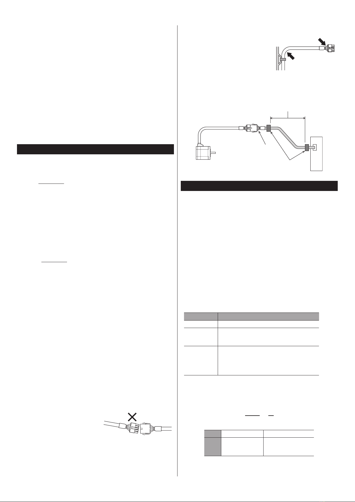
•When inserting the connector
Hold the connector main body, and insert it
in straight securely. Inserting the connector
in an inclined state may result in damage to
terminals or a connection failure.
•When pulling out the connector
Pull out the connector in straight while releasing the lock part of the connector. Pulling
out the connector with holding the cable may result in damage to the connector.
•Bending radius of cable
Use the cable in a state where the bending
radius of the cable is more than six times of
the cable diameter.
Do not bend the lead wires part or x it
with a clamp. Doing so may cause damage
to the connector. More than 6 times
of cable diameter
Do not bend the lead wires part
•How to x the cable
Fix the cable near the connector so that stress is not applied to the connector part.
Use a wide clamp or x the connector at two places to prevent stress from being applied
to the connector.
In the case of a exible cable,
this area is a movable range.
Fix
Driver
Motor
Do not bend the lead wires
part or x with a clamp
Preparation
Checking the product
Verify that the items listed below are included. Report any missing or damaged items to
the Oriental Motor sales oce from which you purchased the product.
yDriver...................................................................1 unit
yCN1 connector (6 pins).................................1 pc.
yCN3 connector (5 pins).................................1 pc.
yCN5 connector (36 pins) ..............................1 pc.
yConnector wiring lever (for CN3)..............1 pc.
ySeal (for CN5)....................................................1 pc. *
yOPERATING MANUAL Driver Edition.......1 copy (this document)
* To distinguish from connectors of other series, put the seal on the CN5 connector to
use.
Included connector model
There are two types of CN3 connectors made by WAGO Corporation and Molex
Incorporated.
There are two types of CN5 connectors made by 3M Company and Molex Incorporated.
Either one of them is included with the product. Check the manufacturer name with the
connector case.
Type Model number (Manufacturer)
CN1 connector MC1,5/6-STF-3,5 (PHOENIX CONTACT GmbH & Co. KG)
CN3 connector
721-205 (WAGO Corporation)
or
54928-0570 (Molex Incorporated)
CN5 connector
Case: 10336-52A0-008 (3M Company)
Connector: 10136-3000PE (3M Company)
or
Case: 54331-1361 (Molex Incorporated)
Connector: 54306-3619 (Molex Incorporated)
How to identify the product model
Verify the model number of the purchased product against the number shown on the
nameplate.
ARD - C
1 2
1 Series name ARD: AR Series driver
2 Power supply input
A: Single-phase 100-115 V
C: Single-phase 200-230 V
S: Three-phase 200-230 V


