yUnauthorized reproduction or copying of all or part of this manual is
prohibited.
yOriental Motor shall not be liable whatsoever for any problems relating
to industrial property rights arising from use of any information, circuit,
equipment or device provided or referenced in this manual.
yCharacteristics, specications and dimensions are subject to change without
notice.
yWhile we make every eort to oer accurate information in the manual,
we welcome your input. Should you nd unclear descriptions, errors or
omissions, please contact your nearest Oriental Motor sales oce.
yis a registered trademark or trademark of Oriental Motor
Co., Ltd., in Japan and other countries.
© Copyright ORIENTAL MOTOR CO., LTD. 2018
Published in June 2019
echnical Support Tel:(800)468-3982
A.M. to 5:00 P.M., P.S.T. (M-F)
A.M. to 5:00 P.M., C.S.T. (M-F)
.orientalmotor.com
Schiessstraße 44, 40549 Düsseldor
f, Germany
echnical Support Tel:00 800/22 55 66 22
.orientalmotor.de
el:01256-347090
.oriental-motor.co.uk
el:01 47 86 97 50
.orientalmotor.fr
el:02-93906346
.orientalmotor.it
el:+55-11-3266-6018
.orientalmotor.com.br
• Please contact your nearest Oriental Motor oce for further information.
4-8-1Higashiueno
,Taito-ku,Tokyo 110-8536
el:03-6744-0361
.orientalmotor.co.jp
Tel:0800-060708
www.orientalmotor.com.tw
Singapore
Tel:1800-8420280
www.orientalmotor.com.sg
Tel:1800-806161
www.orientalmotor.com.my
Korea
Tel:080-777-2042
www.inaom.co.kr
Tel:1800-888-881
www.orientalmotor.co.th
Tel:400-820-6516
www.orientalmotor.com.cn
Tel:+91-80-41125586
www.orientalmotor.co.in
Hong Kong Branch
Secure the lead wires at the connection part to prevent the
connection part from receiving stress due to the exing of the lead
wires or the lead wires’ own mass. Also, do not excessively bend the
lead wires near the connection part of the connector. Applying stress
on the lead wires may cause poor contact or disconnection, leading to
malfunction or heat generation.
Bend excessivelyHave length
allowances More than 4 times
of the diameter of
the lead wire.
Specications for electromagnetic brake connection
cable
•Connector pin assignments
Pin No. Lead wire color
1 Red
2 Black
•Applicable connector and lead wire
Type Model
Connector housing DF62C-2S-2.2C (HIROSE ELECTRIC CO., LTD.)
Contact DF62-22SCA (HIROSE ELECTRIC CO., LTD.)
Designated crimping tool HT801/DF62-22(10) (HIROSE ELECTRIC CO., LTD.)
Applicable lead wire
AWG22 (0.3 mm2)
Outer sheath diameter:
ø1.2 to 1.5 mm (ø0.05 to 0.06 in.)
Stripping length of wire insulation:
1.8 to 2.3 mm (0.07 to 0.09 in.)
Specications of a power supply for
electromagnetic brake
Model Motor type Power supply voltage Current capacity
A (connector type) PKP24
24 VDC±5%
0.07 A or more
PKP26 0.18 A or more
B (lead wire type)
PKP22 0.05 A or more
PKP23, PKP24 0.07 A or more
PKP26 0.23 A or more
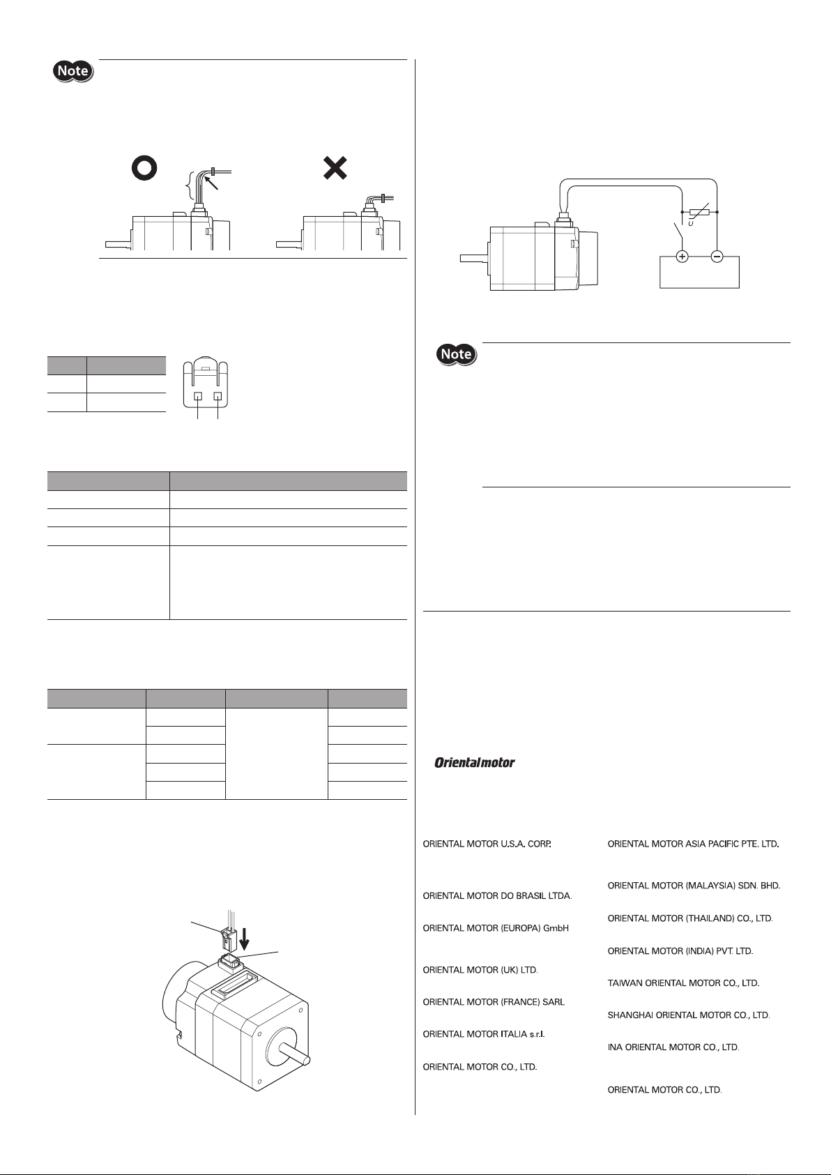
Connecting a power supply for electromagnetic
brake and releasing the electromagnetic brake
1. For the Model A (connector type), connect the electromagnetic brake
connection cable to the electromagnetic brake connector.
Elec
brake connector
tromagnetic brake
tion cable *
* This cable is provided as our product.
2. Connect the varistor (included) in parallel between the 24 VDC terminal
and GND terminal.
The varistor does not have polarity.
3. Connect the electromagnetic brake lead wires to the 24 VDC power
supply.
Connect the red lead wire to 24 VDC terminal, and the black lead wire to
GND terminal.
Va
Switch
Motor
24 VDC
power supply
Black Red
4. Turn on the 24 VDC power supply.
The electromagnetic brake is released.
yDo not apply the voltage beyond its specications. Doing so may
increase heat generation in the electromagnetic brake, resulting in
damage to the motor. Conversely, insucient voltage may prevent
the brake from releasing.
yBe sure to connect the varistor to protect the contact of the switch
or to prevent electrical noise.
yThe electromagnetic brake lead wires have polarities, so connect
them in the correct polarities. If the lead wires are connected with
their polarities reversed, the electromagnetic brake will not operate
properly.


