manuals.online logo
Brands
  1. Home
  2. •
  3. Brands
  4. •
  5. Oriental motor
  6. •
  7. Engine
  8. •
  9. Oriental motor PK Series User manual

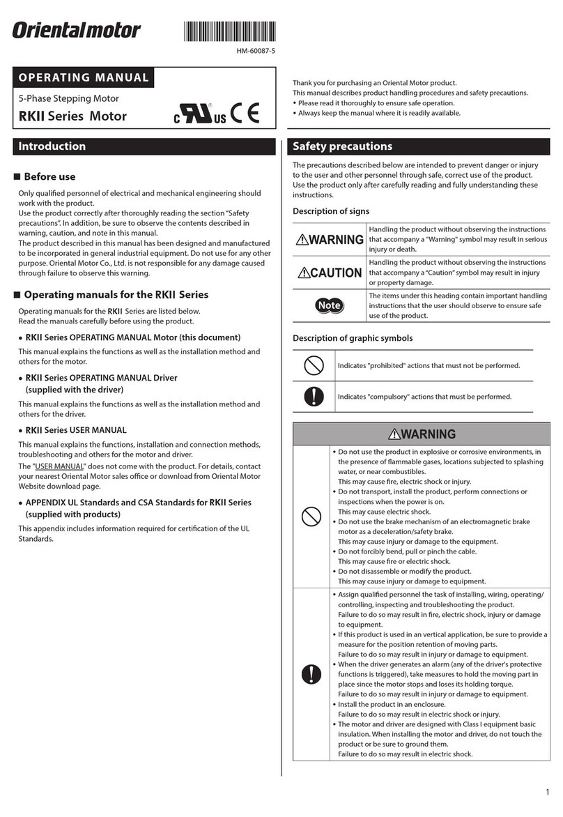
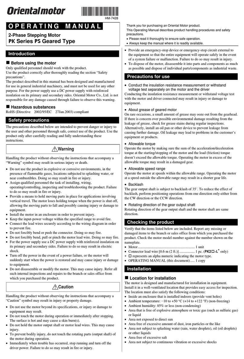
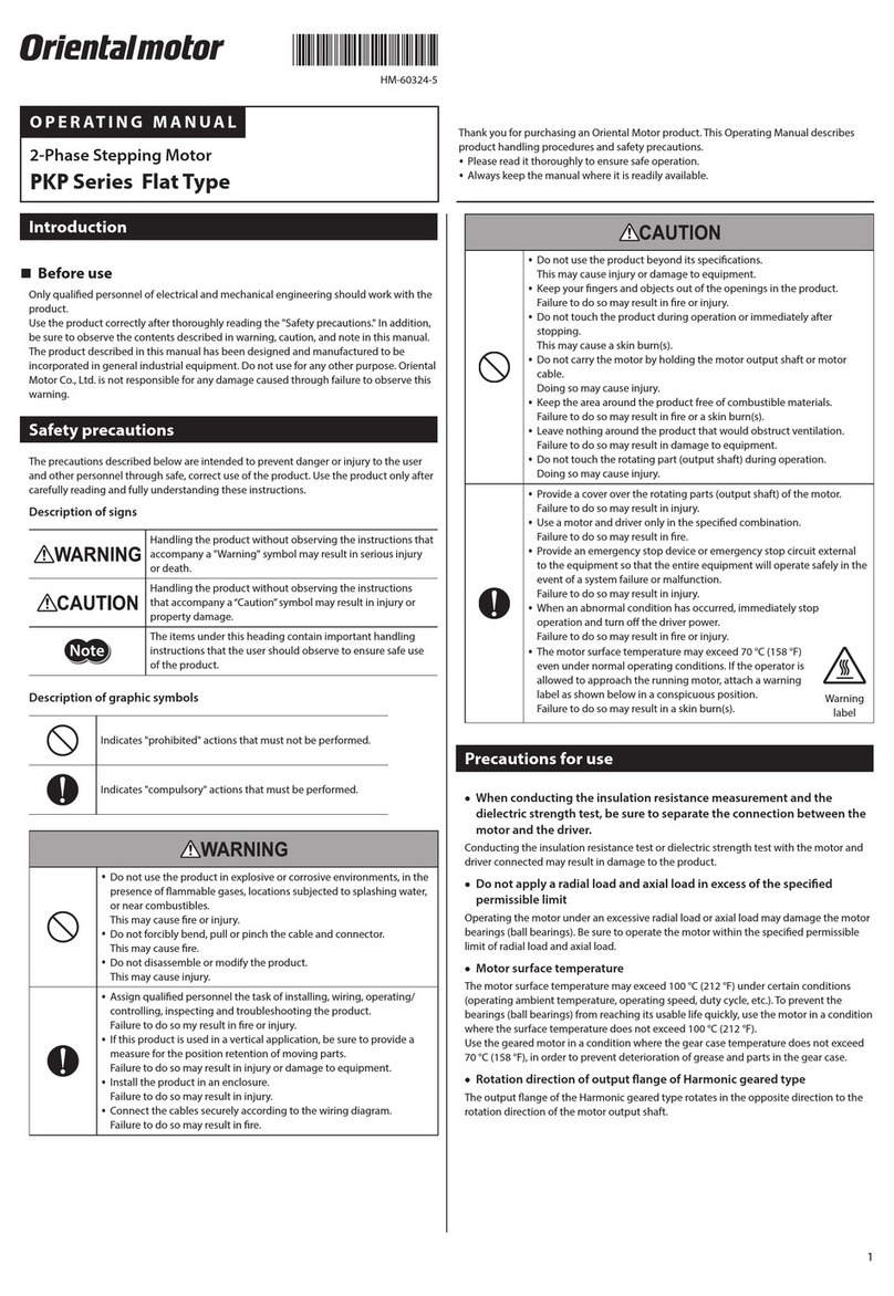
Oriental motor PK Series User manual

Introduction
Before use
This product must be handled by qualied personnel with
expert knowledge of electrical and mechanical engineering.
Use the product correctly after thoroughly reading the section
“Safety precautions.” In addition, be sure to observe the
contents described in warning and caution in this manual.
The product described in this manual is designed and
manufactured to be incorporated in general industrial
equipment. Do not use the product for any other purpose.
Oriental Motor shall not be liable whatsoever for any damage
arising from the failure to observe this warning.
Product overview
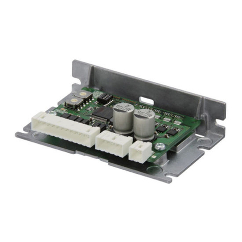
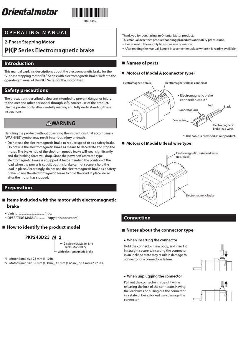
This product is a 2-phase stepping motor employing a terminal-
block connection method.
This product is recognized by UL and certied by CSA, and
bears the CE Marking (Low Voltage Directive) in compliance
with the EN Standards.
Applicable Standards Certication Body Standards File No.
UL 1004-1, UL 1004-2
CSA C22.2 No.100
CSA C22.2 No.77
UL E64199
EN 60034-1, EN 60034-5,
EN 60664-1
Conforming to the respective
standards.
Degree of
protection
IP65 (Excluding the gap between the shaft and the
ange)
Operating
environment
Ambient
temperature
−10 to +50 °C (+14 to +122 °F)
(non-freezing)
Humidity 85 % or less (non-condensing)
Altitude Up to 1,000 m (3,300 ft.) above sea
level
Ambient
atmosphere Free from corrosive gases
Installation
conditions
To be incorporated in equipment
Overvoltage category: II
Pollution degree: Class 3 (excluding installation
surface)
Protection against electric shock: Class I equipment
The user is responsible for conrming the EMC compatibility of
the nal equipment incorporating the motor.
RoHS Directive
The products do not contain the substances exceeding the
restriction values of RoHS Directive (2011/65/EU).
Checking the product
Conrm that all of the following items are available. Should you
nd any item missing or damaged, contact the Oriental Motor
sales oce where you purchased the product. Check the motor
model with the nameplate.
yMotor................................... 1 unit
yOPERATING MANUAL..... 1 copy
zModel
Motor identication
A: Single shaft
PK 2 6 4 D A T
PK series
Motor frame size 6
: 56.4 mm (2.22 in.)
Motor case length
Blank: 5 terminals (unipolar)
D: 4 terminals (bipolar)
2: 2-phase
zProduct types
PK264AT PK266AT PK268AT
PK264DAT PK266DAT PK268DAT
The connection methods and rated currents are listed below.
Model Connection method Rated current
PK26AT Unipolar connection 2.0 A/phase
PK26DAT Bipolar connection 2.8 A/phase
Safety precautions
The motor is designed for incorporation into industrial
equipment. Touching the motor during operation may result
in bodily injury or property damage, since the output shaft is
rotating and the surface remains very hot. To prevent injury
or damage to the motor, be sure the motor is handled and
operated only by qualied personnel familiar with operations
involving electronic equipment.
Handling the product without observing the instructions that
accompany a“WARNING”symbol may result in death or serious
bodily injury.
yDo not use the motor in explosive or corrosive environments,
in the presence of ammable gases, near combustible
materials, or locations subjected to the splashing of oil or
other hazardous liquids. Doing so may result in re, electric
shock or injury.
yTurn o the power before working on the product. Failure to
do so may result in electric shock.
yProvide a measure to retain the position of the movable
part of equipment when the product is used in a vertical
application. The motor loses its holding torque when the
power is cut o. Without appropriate measures the movable
part will descend, resulting in injury or damage to equipment.
yInstall the motor inside an enclosure to avoid contact with
the hands, or provide sucient earthing. Failure to do so may
result in electric shock.
yConnect the product correctly and securely according to the
wiring diagram. Failure to do so may result in re or electric
shock.
yAfter connecting the cable, securely x and tighten the
terminal box and cable clamp. Failure to do so may result in
re or electric shock.
yTurn o the power in case of a power failure. Failure to do so
may result in injury or damage to equipment when the motor
starts suddenly upon the recovery of power.
yDo not disassemble or modify the motor. This may cause
electric shock or injury.
Handling the product without observing the instructions that
accompany a“CAUTION”symbol may result in bodily injury or
property damage.
yDo not use the motor beyond its specications. Doing so may
result in electric shock, injury or damage to equipment.
yDo not touch the motor while the motor is conducting
current. Doing so may result in burns.
yUse a round terminal for connection with the Protective Earth
Terminal. Failure to do so may result in re or electric shock.
yDo not carry the motor by its output shaft. Doing so may
result in injury.
ySecurely x the motor to an appropriate metal plate. Failure
to do so may result in injury or damage to equipment.
yProtect the rotating part of the motor (output shaft) with a
cover. Failure to do so may result in injury.
yWhen conducting the insulation resistance measurement
or the dielectric strength test, be sure to separate the
connection between the motor and the driver. Failure to do
so may result in damage to equipment.
yImmediately when trouble has occurred, stop running and
turn o the power. Failure to do so may result in re, electric
shock or injury.
yDispose the product correctly in accordance with laws and
regulations, or instructions of local governments.
yProvide an emergency-stop device or emergency-stop circuit
external to the equipment so that the entire equipment will
operate safely in the event of a system failure or malfunction.
Failure to do so may result in injury.
Precautions for use
•Drive unit
Use a motor driver unit appropriate for the method of motor
connection.
•Connecting the motor
Use a multi-core cable of AWG26 to 16 (0.14 to 1.25 mm2)
[7 to 13 mm (0.28 to 0.51 in.) in outer diameter] for motor
connection. Strip away 40 to 50 mm (1.57 to 1.97 in.) of sheath
from the end of the cable. Stripping the cable sheath by more
than 50 mm (1.97 in.) will reduce the sealing eect of the cable
clamp.
•Cable clamp
“Cable clamp” is a section through which a cable passes. The
cable clamp conforms to the IP65 specication and consists of
the cap, gasket and receptacle. To ensure watertightness at the
cable clamp, tighten the cap after conrming that the cover of
the connection cable is securely sealed by the gasket.
•Motor case temperature
The motor is designed to the class B insulation specication.
When operating the motor, keep the motor case temperature to
100 °C (212 °F) or below. Operating the motor at temperatures
above 100 °C (212 °F) will shorten the life of the motor coil and
ball bearing. [The maximum temperature is 75 °C (167 °F) if the
equipment is to receive UL/CSA certication, because the motor
must conform to the class A insulation requirement.]
Installation
Installation requirements
The motor is designed to be incorporated in equipment. It must
be used in an environment conforming to overvoltage category
II, pollution degree of class 3 and protection against electric
shock of class I equipment.
Degree of protection: IP65 (Excluding the gap between the
shaft and the ange)
Install the motor in a well-ventilated location that provides
easy access for inspection. The locaton must also satisfy the
following conditions:
yInside an enclosure that is installed indoors (provide vent
holes)
yOperating ambient temperature: −10 to +50 °C (+14 to
+122 °F) (non-freezing)
yOperating ambient humidity: 85 % or less (non-condensing)
yArea free of explosive atmosphere or toxic gas (such as
sulfuric gas) or liquid
yArea not exposed to direct sun
yArea free of excessive salt
yArea not subject to continuous vibration or excessive shocks
yArea free of excessive electromagnetic noise (from welders,
power machinery, etc.)
yArea free of radioactive materials, magnetic elds or vacuum
HM-7416-5
日本語は、英語の後ろに記載しています。
OPERATING MANUAL
Thank you for purchasing an Oriental Motor product.
This Operating Manual describes product handling procedures and safety precautions.
yPlease read it thoroughly to ensure safe operation.
yAlways keep the manual where it is readily available.
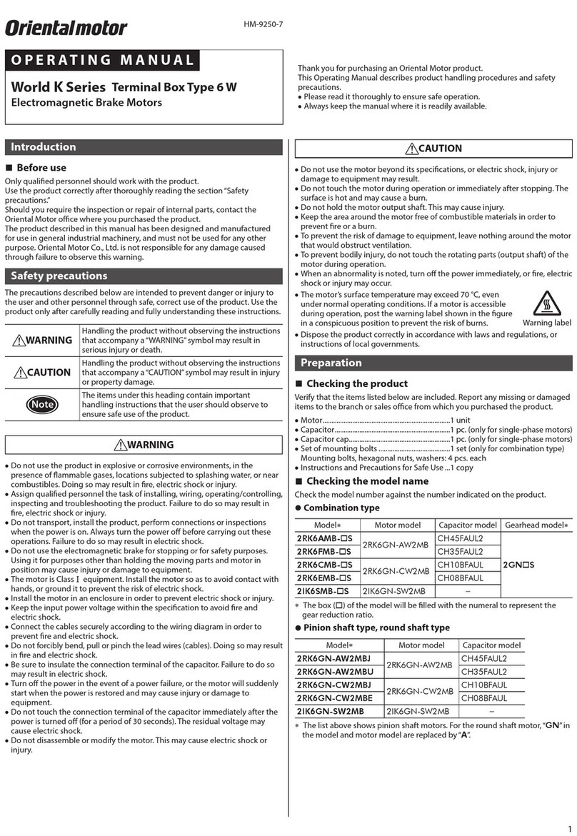
2-Phase Stepping Motor PK Series
Standard Type IP65 rated motor
PK26AT, PK26DAT
yUnauthorized reproduction or copying of all or part of this manual is prohibited.
yOriental Motor shall not be liable whatsoever for any problems relating to industrial property rights arising from use of any
information, circuit, equipment or device provided or referenced in this manual.
yCharacteristics, specications and dimensions are subject to change without notice.
yWhile we make every eort to oer accurate information in the manual, we welcome your input. Should you nd unclear
descriptions, errors or omissions, please contact your nearest Oriental Motor sales oce.
yis a registered trademark or trademark of Oriental Motor Co., Ltd., in Japan and other countries.
© Copyright ORIENTAL MOTOR CO., LTD. 2006
Published in April 2021
• Please contact your nearest Oriental Motor oce for further information.
Tel:0800-060708
www.orientalmotor.com.tw
Korea
Tel:080-777-2042
www.inaom.co.kr
Tel:1800-888-881
www.orientalmotor.co.th
Tel:400-820-6516
www.orientalmotor.com.cn
T
echnical Support Tel:800-468-3982
8:30am EST to 5:00pm PST
(M-F)
www
.orientalmotor.com
Schiessstraße 44, 40549 Düsseldor
f, Germany
T
echnical Support Tel:00 800/22 55 66 22
www
.orientalmotor.de
T
el:+44-1256347090
www
.oriental-motor.co.uk
T
el:+33-1 47 86 97 50
www
.orientalmotor.fr
Tel:+39-02-93906347
www.orientalmotor.it
4-8-1Higashiueno,Taito-ku,Tok
yo 110-8536
Japan
Tel:+81-3-6744-0361
www.orientalmotor.co.jp
Singapore
Tel:1800-842-0280
www.orientalmotor.com.sg
Tel:1800-806-161
www.orientalmotor.com.my
Tel:1800-120-1995 (For English)
1800-121-4149 (For Hindi)
www.orientalmotor.co.in
Installation method
Mount the motor on the smooth surface of a metal plate.
When installing the motor, secure it with four bolts (not
included) through the four mounting holes provided in the
motor’s installation surface, so as to leave no gaps between the
installation surface and metal plate.
Bolt size: M4
Tightening torque: 2 N·m (280 oz-in)
Insert the pilot located on the motor’s installation surface into
the ange pilot.
Metal plate
Flange pilot
Installing the load
When installing a load to the motor, align the centers of the
motor’s output shaft and load shaft.
Be careful not to damage the output shaft or bearings within
when installing a exible coupling or pulley to the motor’s
output shaft.
Permissible radial load and permissible
axial load
The radial load and axial load of the motor’s output shaft must
not exceed the permissible values shown in the table below.
•Permissible radial load [N (lb.)]
Distance from the tip of motor’s output shaft [mm (in.)]
0 (0) 5 (0.20) 10 (0.39) 15 (0.59)
54 (12.1) 67 (15) 89 (20) 130 (29)
•Permissible axial load [kg (lb.)]
PK264 0.6 (1.32) *The axial value must be kept
at or below the mass (*) of the
motor.
PK266 0.9 (1.98) *
PK268 1.2 (2.64) *
Connection
Connect the PK26AT to terminals 1 to 5 on the terminal.
Connect the PK26DAT to terminals 2 to 5 on the terminal.
1
For PK26AT (1 to 5)
For PK26DAT
(2 to 5)
2345
Terminal block
Wiring diagrams
•PK26AT (Unipolar connection)
Phase A
2
11
3
4
5
+C
OM +C
OM
Phase B
Phase A Phase B
•PK26DAT (Bipolar connection)
Phase
A
3
4
5
Phase
B
2
Connection method
Connect the respective wires as illustrated below.
Connect either the internal Protective Earth Terminal or external
Protective Earth Terminal to the ground. Use the internal
Protective Earth Terminal in a corrosive environment. If the
wiring distance between the motor and driver is long, use the
external Protective Earth Terminal. Use a Protective Earth wire
thicker than AWG18 (0.75 mm2).
Protective Earth wire
for external Protec
tive
Earth Terminal
(AWG18 or more)
Motor lead wires
(AWG26 to 16)
Protective Earth wire
f
or internal Protective
Ear
th Terminal
(A
WG18 or more)
Multi-core cable
[Outer diameter:
7 to 13 mm
(0.28 to 0.51 in.)]
1. Remove the terminal box
Loosen the mounting screws (M3) for securing the terminal box,
then remove the terminal box from the motor.
Terminal box
O-ring
2. Repair the connection cable
yStripping the cable sheath by more than 50 mm (1.97 in.)
from the end of the cable will reduce the sealing eect of the
cable clamp.
yWhen using the internal Protective Earth Terminal, crimp a
round terminal (M4) to the Protective Earth wire.
Receptacle
Gasket
Cap
40 to 50 mm
(1.57 to 1.97 in.)
6 mm (0.24 in.)
3. Connect the terminal
Loosen the screws on the respective terminals on the terminal
block, insert the motor lead wires from the openings, and then
tighten the screws.
Tightening torque: 0.6 N·m (85 oz-in)
4. Connect the Protective Earth Terminal
Connect to the minimum distance.
yUsing the internal Protective Earth Terminal
Connect the Protective Earth wire to the Protective Earth
Terminal.
Tightening torque: 1.2 N·m (170 oz-in)
Protective Earth wire
(AWG18 or more)
Pr
otective Earth Terminal
yUsing the external Protective Earth Terminal
Two screw holes are provided for connecting the Protective
Earth Terminal. Use a round terminal (M4) to connect one of the
two points to the ground.
Tightening torque: 1.2 N·m (170 oz-in)
Grounding
5. Install the terminal box
Conrm that an O-ring is set in the groove, align the motor case
and terminal cover, then tighten the mounting screws (M3) for
securing the terminal cover.
Tightening torque: 0.5 N·m (71 oz-in)
6. Tighten the cable cap
Place the gasket on the
receptacle and tighten the
cap. Before tightening the cap,
conrm that the sheath of the
cable is sealed by the gasket.
Tightening torque: 4.0 to 5.0 N·m
(560 to 710 oz-in)
Adjust the tightening torque
depending on the diameter and
material of the cable.
Inspection
It is recommended that the following items be checked
regularly after the motor has been operated. Should any
abnormality be found, stop using the motor and contact your
nearest Oriental Motor sales oce.
yIs there any abnormal noise coming from the bearings (ball
bearings) of the motor or other parts?
yIs there a loose terminal box or cable cap?
yIs there any scratch or sign of stress on the connection cable?
yAre the output shaft and load shaft properly aligned at their
centers?
はじめに

お使いになる前に
製品の取り扱いは、適切な資格を有する人が行なって
ください。
お使いになる前に、「安全上のご注意」をよくお読みの
うえ、正しくお使いください。また、本文中の警告・注
意に記載されている内容は、必ずお守りください。
この製品は、一般的な産業機器への組み込み用として
設計・製造されています。その他の用途には使用しない
でください。この警告を無視した結果生じた損害の補
償については、当社は一切その責任を負いませんので、
あらかじめご了承ください。

製品の概要
この製品は、端子台接続方式を採用した 2 相ステッピ
ングモーターです。
この製品は、UL規格、CSA規格の認定を取得し、EN
規格にもとづいて CEマーキング(低電圧指令)を実施し
ています。
適用規格 認定機関 規格ファイル No.
UL 1004-1、UL 1004-2
CSA C22.2 No.100
CSA C22.2 No.77
UL E64199
EN 60034-1、EN 60034-5、
EN 60664-1 規格対応品
保護等級 IP65(モーターシャフト貫通部を除く)
使用環境
周囲温度 −10 ~ +50 °C(凍結しないこと)
湿度 85 %以下(結露しないこと)
高度 海抜1,000 m以下
雰囲気 腐食性ガスがないこと
設置条件
機器組み込み
過電圧カテゴリー:Ⅱ
汚染度:クラス 3(取付面を除く)
感電保護:クラスⅠ機器
EMCの適合性は、お客様の責任で確認していただく必
要があります。

RoHS指令
RoHS指令(2011/65/EU)の規制値を超える物質は含
有していません。

製品の確認
次の付属品がすべて揃っていることを確認してくださ
い。不足したり、破損しているときは、お買い求めの
支店または営業所までご連絡ください。モーターの品
名は、銘板に記載された品名で確認してください。
yモーター ............1台
y取扱説明書 ........1部

品名の見方
モーター識別
A:片軸
PK 2 6 4 D A T
PKシリーズ
モーター取付角寸法6:
56.4mm
モーターケース長さ
なし:5端子(ユニポーラ
)
D:4端子(バイポーラ)
2:2相

製品の種類
PK264AT、PK266AT、PK268AT
PK264DAT、PK266DAT、PK268DAT
結線方式と定格電流は、次のとおりです。
品名 結線方式 定格電流
PK26AT ユニポーラ結線 2.0 A/相
PK26DAT バイポーラ結線 2.8 A/相
安全上のご注意
モーターは、産業機器への組み込み用に設計されてい
ます。運転中は、出力軸が回転し、表面が高温になる
ため、身体への危険、または物的損害が発生する可能
性があります。けがやモーターの損害を防止し、回避
するため、電子機器の作業に精通した有資格者のみが
モーターの取り扱い・操作を行なってください。
この警告事項に反した取り扱いをすると、死亡または
重傷を負う場合がある内容を示しています。
y爆発性雰囲気、引火性ガスの雰囲気、腐食性の雰囲気、
可燃物のそば、および油などの有害な液体がかかる
場所では使用しないでください。火災・感電・けがの
原因になります。
y作業をするときは、電源を切ってから行なってくだ
さい。感電の原因になります。
y昇降装置に使用するときは、可動部の位置保持対策
を行なってください。モーターは電源オフ時に、保
持力がなくなります。可動部が落下して、けが・装置
破損の原因になります。
y設置するときは、モーターに手が触れないようにす
るか、接地してください。感電の原因になります。
y接続は接続図にもとづき、確実に行なってください。
火災・感電の原因になります。
yケーブル接続後は、端子箱、ケーブルクランプを確
実に固定、締め付けてください。火災・感電の原因に
なります。
y停電したときは、電源を切ってください。停電復旧
時にモーターが突然起動して、けが・装置破損の原因
になります。
yモーターは、分解・改造しないでください。感電・け
がの原因になります。
この注意事項に反した取り扱いをすると、傷害を負う
または、物的損害が発生する場合がある内容を示して
います。
yモーターの仕様値を超えて使用しないでください。
感電・けが・装置破損の原因になります。
yモーターに通電中は、モーターに触れないでくださ
い。やけどの原因になります。
y保護接地端子と接続するときは、丸形端子を使用し
てください。火災・感電の原因になります。
y持ち運ぶときは、モーターの出力軸を持たないでく
ださい。けがの原因になります。
yモーターは、金属板に確実に固定してください。けが・
装置破損の原因になります。
yモーターの回転部(出力軸)に、カバーを設けてくだ
さい。けがの原因になります。
y絶縁抵抗測定、絶縁耐圧試験を行なうときは、モー
ターとドライバを切り離してください。製品破損の
原因になります。
y異常が発生したときは、ただちに運転を停止して、
電源を切ってください。火災・感電・けがの原因にな
ります。
y製品は、法令または自治体の指示に従って、正しく
処分してください。
y装置の故障や動作の異常が発生したときに、装置全
体が安全な方向へはたらくよう、非常停止装置また
は非常停止回路を外部に設置してください。けがの
原因になります。
使用上のご注意
•駆動装置
モーターの結線方式に合った駆動装置を使用してくだ
さい。
•モーターの接続
モーターの接続には AWG26 ~ 16(0.14 ~
1.25 mm2)の多心ケーブル(外径7 ~ 13 mm)を使用
してください。ケーブル先端の被覆は、40 ~ 50 mm
剥いてください。50 mm以上剥くと、ケーブルクラン
プのシール効果が失われます。
•ケーブルクランプ
ケーブルクランプとは、IP65 仕様に対応したケーブ
ル貫通部のことで、キャップ、ガスケット、およびレ
セプタクルで構成されています。ケーブルクランプの
防水性を確保するため、ガスケットで多心ケーブルの
被覆が確実にシールされていることを確認してから、
キャップを締め付けてください。
•モーターケース温度
モーターの絶縁階級は B種絶縁です。モーターを運転
するときは、モーターケースの温度を 100 °C以下に
抑えてください。100 °Cを超えて運転すると、モー
ターの巻線やボールベアリングの寿命が短くなります。
(UL/CSA規格取得時は、モーター部 A種絶縁のため、
75 °C以下となります)
設置

必要条件
モーターは、機器組み込み、過電圧カテゴリー:Ⅱ、
汚染度:クラス 3、感電保護:クラスⅠ機器の環境で使
用するよう設計されています。
保護等級 IP65(モーターシャフト貫通部を除く)
モーターは、風通しがよく、点検が容易な、次の場所
に設置してください。
y屋内に設置された筐体内(換気口を設けてください)
y使用周囲温度 −10 ~ +50 °C(凍結しないこと)
y使用周囲湿度 85 %以下(結露しないこと)
y爆発性雰囲気、有害なガス(硫化ガスなど)、および
液体のないところ
y直射日光が当たらないところ
y塩分の少ないところ
y連続的な振動や過度の衝撃が加わらないところ
y電磁ノイズ(溶接機、動力機器など)が少ないところ
y放射性物質や磁場がなく、真空でないところ
HM-7416-5
取扱説明書
お買い上げいただきありがとうございます。
この取扱説明書には、製品の取り扱いかたや安全上の注意事項を示しています。
y取扱説明書をよくお読みになり、製品を安全にお使いください。
yお読みになったあとは、いつでも見られるところに必ず保管してください。
2 相ステッピングモーターPKシリーズ
標準タイプ保護等級 IP65 仕様
PK26AT、PK26DAT
yこの取扱説明書の一部または全部を無断で転載、複
製することは、禁止されています。
y取扱説明書に記載されている情報、回路、機器、お
よび装置の利用に関して産業財産権上の問題が生じ
ても、当社は一切責任を負いません。
y製品の性能、仕様および外観は改良のため予告なく
変更することがありますのでご了承ください。
y取扱説明書には正確な情報を記載するよう努めてい
ますが、万一ご不審な点や誤り、記載もれなどにお
気づきの点がありましたら、最寄りのお客様ご相談
センターまでご連絡ください。
y は、日本その他の国におけるオリ
エンタルモーター株式会社の登録商標または商標で
す。
© Copyright ORIENTAL MOTOR CO., LTD. 2006
2021 年4 月制作
WEBサイトでもお問い合わせやご注文を受け付けています。
https://www.orientalmotor.co.jp/
技術的なお問い合わせ・訪問・お見積・ご注文
お客様ご相談センター
受付時間 平日/9:00〜19:00
東 京 TEL 0120-925-410 FAX 0120-925-601
名古屋 TEL 0120-925-420 FAX 0120-925-602
大 阪 TEL 0120-925-430 FAX 0120-925-603
TEL 0120-911-271 FAX 0120-984-815
故障かな?と思ったときの検査修理窓口
アフターサービスセンター
受付時間 平日/9:00〜17:30
お問い合わせ窓口
(フリーコールです。携帯・PHSからもご利用いただけます。)

設置方法
モーターは、平滑な金属板に設置してください。
モーター取付面にある 4 か所の取付穴を使用して、金
属板との間にすき間ができないように、4 本のボルト
(付属していません)で固定してください。
ボルトの呼び:M4
締付トルク:2 N·m
モーター取付面にあるインローはインロー受けにはめ
こんでください。
金属板
インロー受け

負荷の取り付け
負荷をモーターに取り付けるときは、モーター出力軸
と負荷の軸中心線を揃えてください。
フレキシブルカップリングやプーリーをモーター出力
軸に取り付けるときは、出力軸や軸受けに損傷を与え
ないでください。

許容ラジアル荷重と許容アキシアル
荷重
モーター出力軸のラジアル荷重とアキシアル荷重は、
表の値以下にしてください。
•許容ラジアル荷重(N)
モーター出力軸先端からの距離(mm)
0 5 10 15
54 67 89 130
•許容アキシアル荷重
PK264 0.6 ※ ※印はモーター質量(kg)です。
アキシアル荷重は、モーター
自重以下にしてください。
PK266 0.9 ※
PK268 1.2 ※
接続
PK26ATは、1 ~ 5 の端子に接続してください。
PK26DATは、2 ~ 5 の端子に接続してください。
1
PK26AT
で使用(1〜5)
PK26DATで使用(2〜5
)
2345
端子台

接続図
PK26AT
(ユニポーラ結線)
A相
2
11
3
4
5
+COM +COM
B相
A相 B相
PK26DAT
(バイポーラ結線)
A相
3
4
5
B相
2

接続方法
図のように接続してください。
内部保護接地端子と外部保護接地端子のどちらかを接
地してください。腐食の可能性がある使用環境では、
内部保護接地端子をお使いください。また、モーター
とドライバの配線距離が長い場合は、外部保護接地端
子をお使いください。
保護接地線は、AWG18(0.75 mm2)より太いものを
使用してください。
外部保護接地端子
保護接地線
(AWG18以上)
モーター線
(AWG26〜16)
内部保護接地端子
保護接地線
(AWG18以上)
多心ケーブル
(外径7〜13mm)
1. 端子箱の取り外し
端子箱取付ねじ(M3)を緩め、端子箱をモーター部か
ら取り外します。
端子箱
Oリ
ング
2. 接続ケーブルの加工
yケーブル先端の被覆を 50 mm以上剥くと、ケーブル
クランプのシール効果が失われます。
y内部で接地するときは、丸形端子(M4)を保護接地線
に圧着します。
40〜50mm
6mm
レセプタ
クル
ガスケット
キャップ
3. 端子台への接続
端子台のねじを緩め、モーター線を開口部から差し込
み、ねじを締め付けます。
締付トルク:0.6 N·m
4. 保護接地端子への接続
最短距離で接地してください。
y内部保護接地端子を使う場合
保護接地線を保護接地端子に接続します。
締付トルク:1.2 N·m
保護接地線
(AWG18以上)
保護接地端子
y外部保護接地端子を使う場合
保護接地端子のねじ穴は 2 か所あります。丸形端子
(M4)を使用して、どちらかを接地してください。
締付トルク:1.2 N·m
接地
5. 端子箱の取り付け
Oリングが溝に装着されていることを確認し、端子箱
の向きをモーターケースに合わせて、端子箱取付ねじ
(M3)を締め付けます。
締付トルク:0.5 N·m
6. キャップの締め付け
ガスケットをレセプタクルにはめ込み、多心ケーブル
の被覆がガスケットで確実にシールされていることを
確認してから、キャップを締め付けます。
締付トルク:4.0 ~ 5.0 N·m
締付トルクは、ケーブル径・材質により調整してくださ
い。
点検
モーターの運転後は、定期的に次の項目について点検
することをおすすめします。異常があるときは使用を
中止し、お客様ご相談センターにお問い合わせくださ
い。
yモーターの軸受部(ボールベアリング)などから異常
な音が発生していないか。
y端子箱やキャップに緩みがないか。
y多心ケーブルに傷やストレスがないか。
y出力軸と負荷軸に心ズレが出ていないか。

This manual suits for next models

6

Other Oriental motor Engine manuals

Oriental motor BX2 Driver Edition Series User manual

Oriental motor

Oriental motor BX2 Driver Edition Series User manual

Oriental motor 0GN KA Series User manual

Oriental motor

Oriental motor 0GN KA Series User manual

Oriental motor PK Series User manual

Oriental motor

Oriental motor PK Series User manual

Oriental motor US Series User manual

Oriental motor

Oriental motor US Series User manual

Oriental motor K Series User manual

Oriental motor

Oriental motor K Series User manual

Oriental motor PK Series User manual

Oriental motor

Oriental motor PK Series User manual

Oriental motor World K Series User manual

Oriental motor

Oriental motor World K Series User manual

Oriental motor 2IK6GN-AWTJ User manual

Oriental motor

Oriental motor 2IK6GN-AWTJ User manual

Oriental motor PK Series User manual

Oriental motor

Oriental motor PK Series User manual

Oriental motor 4IK25GN-AW2TJ User manual

Oriental motor

Oriental motor 4IK25GN-AW2TJ User manual

Oriental motor PKP Series User manual

Oriental motor

Oriental motor PKP Series User manual

Oriental motor V Series User manual

Oriental motor

Oriental motor V Series User manual

Oriental motor BLM230- B Series User manual

Oriental motor

Oriental motor BLM230- B Series User manual

Oriental motor BLV Series User manual

Oriental motor

Oriental motor BLV Series User manual

Oriental motor US Series User manual

Oriental motor

Oriental motor US Series User manual

Oriental motor BLV Series User manual

Oriental motor

Oriental motor BLV Series User manual

Oriental motor AXH Series User manual

Oriental motor

Oriental motor AXH Series User manual

Oriental motor BLV Series User manual

Oriental motor

Oriental motor BLV Series User manual

Oriental motor K II S Series User manual

Oriental motor

Oriental motor K II S Series User manual

Oriental motor SMK Series User manual

Oriental motor

Oriental motor SMK Series User manual

Oriental motor BMU Series User manual

Oriental motor

Oriental motor BMU Series User manual

Oriental motor Super Vexta UPD564-NAA User manual

Oriental motor

Oriental motor Super Vexta UPD564-NAA User manual

Oriental motor K Series User manual

Oriental motor

Oriental motor K Series User manual

Oriental motor BLE Series User manual

Oriental motor

Oriental motor BLE Series User manual

Popular Engine manuals by other brands

Volvo Penta TAD1630G Workshop manual

Volvo Penta

Volvo Penta TAD1630G Workshop manual

Nice NEO S Installation and use instructions and warnings

Nice

Nice NEO S Installation and use instructions and warnings

GPX ZS194MQ manual

GPX

GPX ZS194MQ manual

Kohler KD400 Specifications

Kohler

Kohler KD400 Specifications

Robin EH36 Service manual

Robin

Robin EH36 Service manual

Booma-RC DLE111 user manual

Booma-RC

Booma-RC DLE111 user manual

NEROXDOMO ECO 35 installation manual

NEROXDOMO

NEROXDOMO ECO 35 installation manual

Parker V14-110 Service manual

Parker

Parker V14-110 Service manual

Kohler KS530 owner's manual

Kohler

Kohler KS530 owner's manual

Finish Thompson M Series Operation and parts manual

Finish Thompson

Finish Thompson M Series Operation and parts manual

Champion C46565 user manual

Champion

Champion C46565 user manual

Kohler 40EOZD installation instructions

Kohler

Kohler 40EOZD installation instructions

SIMONINI MINI 2 EVO Installation

SIMONINI

SIMONINI MINI 2 EVO Installation

Regal Genteq Evergreen EM installation guide

Regal

Regal Genteq Evergreen EM installation guide

CAME OPP001 Installation, operation and maintenance manual

CAME

CAME OPP001 Installation, operation and maintenance manual

Thermador VTR1030W installation instructions

Thermador

Thermador VTR1030W installation instructions

Chevrolet CT525 Technical manual

Chevrolet

Chevrolet CT525 Technical manual

ZIEHL-ABEGG ZAS0 Amendment of the original operating instructions

ZIEHL-ABEGG

ZIEHL-ABEGG ZAS0 Amendment of the original operating instructions

manuals.online logo
manuals.online logoBrands
  • About & Mission
  • Contact us
  • Privacy Policy
  • Terms and Conditions

Copyright 2025 Manuals.Online. All Rights Reserved.