• Area that is free of explosive atmosphere or toxic gas (such as
sulfuric gas) or liquid
• Area not exposed to direct sun
• Area free of excessive amount of dust, iron particles or the like
• Area not subject to splashing water (rains, water droplets), oil (oil
droplets) or other liquids
• Area not subject to continuous vibration or excessive shocks
• Area free of radioactive materials, magnetic fields or vacuum
• Area free of excessive electromagnetic noise (from welders,
power machinery, etc.)
When using near a switching circuit or high-frequency power
supply, the induced current may flow inside the fan due to
electromagnetic noise (conductive noise, radiative noise). If the
induced current flows, the electric corrosion is caused in the
bearings of the fan. As a result, it may generate the noise or
shorten the service life of the products. Use the fan in the
environment that the electromagnetic noise does not cause.
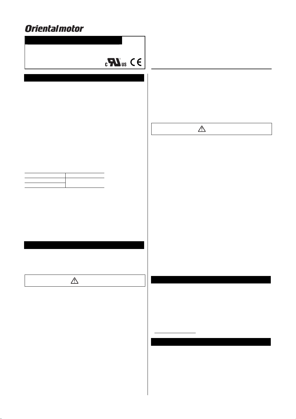
How to install the fan
Install the fan onto an appropriate flat metal plate having excellent
vibration resistance and heat conductivity. See the panel cut-out,
mounting-hall reference drawing for information on how to provide
mounting holes on the equipment used and secure the fan with
screws. For air orientation and rotational direction, see the
indications shown on the fan’s side frame.
Model Screw size Tightening torque
MDA625 M3 0.4 N·m (3.5 lb-in)
Other MDA series M4 0.6 N·m (5.3 lb-in)
Connector housings · Contacts
Manufacturer: J.S.T. Mfg Co., Ltd.
Housings model: SMR-03V-N (3 poles), SMR-04V-N (4 poles)
Contacts model: SYM-001T-P0.6
Connection of the power supply
Connect the red wire to the
positive (+) power supply and
the black wire to the ground
connection.
Check the voltage specification
Red
Black
Yellow GND
Alarm output
+ DC powe
supply
on the product identification plate and input the correct voltage. Use
a DC power supply having a rise time of 100 ms or less.
Connection and specifications of the alarm
Low-speed alarm, electronic alarm type
Output mode Output condition
Open collector output Normal operation: L level
Alarm output: H level
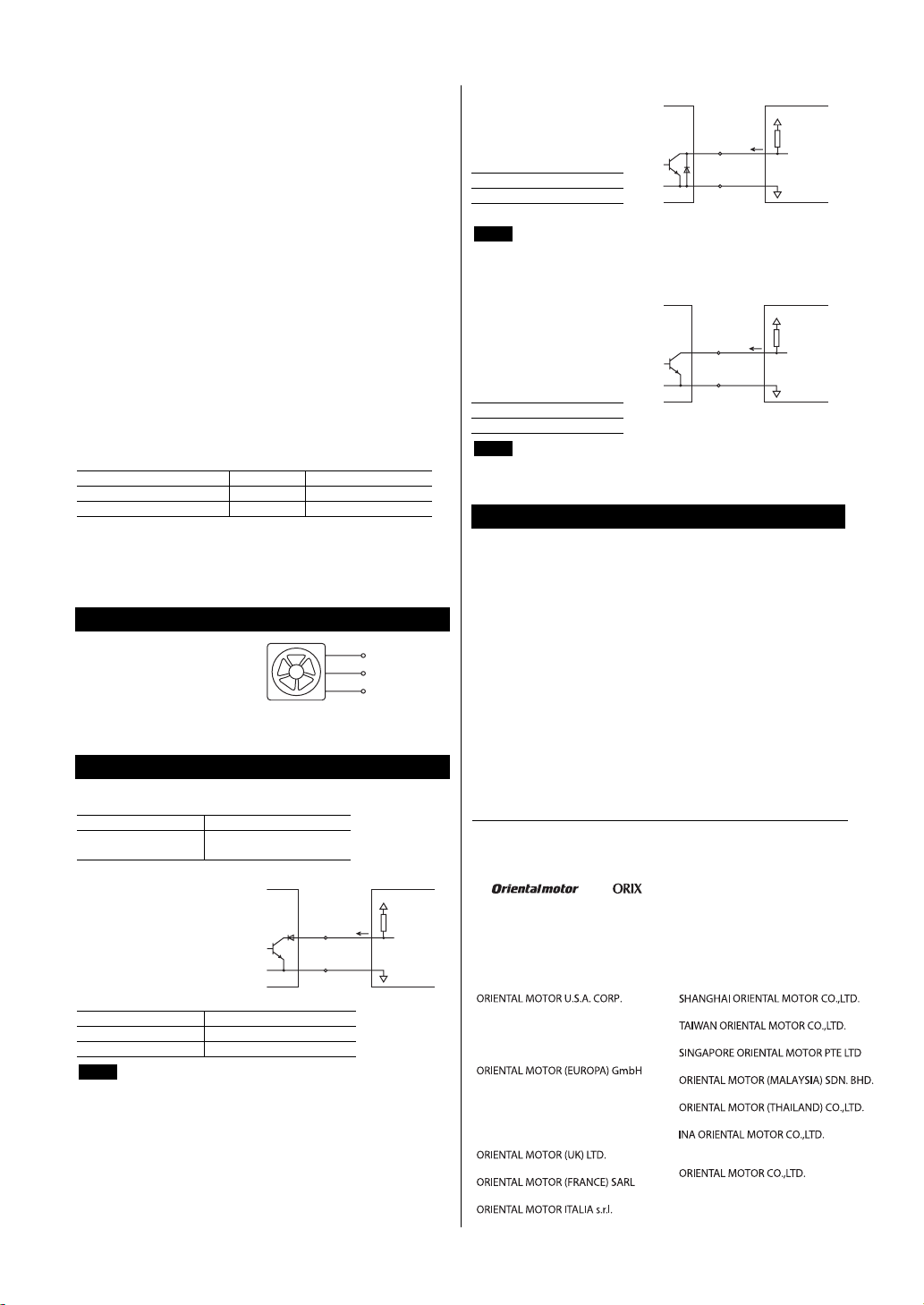
• MDA625 type, MDA825 type, MDA925 type
The yellow wire is lead wire for
the alarm circuit. Connect this
wire to the client’s as shown in
the figure.
Yellow
Black
Fan
Client's circuit
R
15 mA
or less
GND
30 VDC or less
0 V
Model Alarm activation speed
MDA625, MDA825 2300±400 r/min or less
MDA925 1900±400 r/min or less
Note The low-speed alarm type of fan is not equipped with a
delayed trip-point alarm circuit. Therefore, an external
delay function is necessary to avoid the detection of fan
start. The set time of the delay function should be at least
10 seconds.
• MDA1225 type
The yellow wire is lead wire for
the alarm circuit. Connect
these wires to the client’s
circuit as shown in the figure.
Alarm activation speed
2100±400 r/min or less
30 VDC or less
Yellow
Black
Fan
Client's circuit
15 mA
or less
Note The low-speed alarm type of fan is equipped with an
internal delayed-start alarm circuit. The alarm function
becomes effective within 10 seconds of the fan start.
• MDA1451 type
The yellow wire is lead wire for
the alarm circuit. GND is
common to the sensor and
power supply. Connect these
wires to the client’s circuit as
shown in the figure.
Alarm activation speed
1800±400 r/min or less
Yellow
Black
Fan
Client's circuit
15 mA
or less
30 VDC or less
Note The low-speed alarm type of fan is equipped with an
internal delayed-start alarm circuit. The alarm function
becomes effective within 10 seconds of the fan start.
Overheat protection
The fan is equipped with an internal protective circuit against
overheating. In the event a lock-up condition is detected, this
function automatically controls the current flow to the fan motor’s
windings, thus preventing the fan blades from locking and burning
out. The fan resumes operation automatically as soon as it is
released from the locked condition. Be sure to shut off the power to
the fan before performing an inspection.
• Unauthorized reproduction or copying of all or part of this
manual is prohibited.
• Characteristics, specifications and dimensions are subject to
change without notice.
• and are registered trademarks or
trademarks of Oriental Motor Co., Ltd., in Japan and other
countries.
© Copyright ORIENTAL MOTOR CO., LTD. 2008
• Please contact your nearest Oriental Motor office for further information.
Technical Support Tel:(800)468-3982
8:30 A.M. to 5:00 P.M., P.S.T. (M-F)
7:30 A.M. to 5:00 P.M., C.S.T. (M-F)
E-mail: techsupport@orientalmotor.com
www.orientalmotor.com
Headquarters and Düsseldorf Office
Tel:0211-52067-00 Fax:0211-52067-099
Munich Office
Tel:089-3181225-00 Fax:089-3181225-25
Hamburg Office
Tel:040-76910443 Fax:040-76910445
Tel:01256-347090 Fax:01256-347099
Tel:01 47 86 97 50 Fax:01 47 82 45 16
Tel:02-93906346 Fax:02-93906348
Tel:(02)8228-0707 Fax:(02)8228-0708
Tel:+65-6745-7344 Fax:+65-6745-9405
Tel:(03)22875778 Fax:(03)22875528
KOREA
Tel:080-777-2042 Fax:02-2026-5495
Headquarters Tokyo, Japan
Tel:03-6744-0361 Fax:03-5826-2576
Tel:+66-2-251-1871 Fax:+66-2-251-1872
Tel:400-820-6516 Fax:021-6278-0269