Oriental motor VCS05 Series User manual

HP-13015-3
ᝢం
ɽʗɹʁʱʽɿʧ˂ʒʬʂʯ˂ʵ
ʛʵʃʳɮʽʟɭʵʉ VCS05 ʁʴ˂ʄ
䈍⾈䈇䈕䈇䈢䈣䈐䈅䉍䈏䈫䈉䈗䈙䈇䉁䈜䇯
䈖䈱ขᛒ⺑ᦠ䈮䈲䇮ຠ䈱ข䉍ᛒ䈇 䈢䉇ో䈱ᵈᗧ㗄䉕␜䈚
䈩䈇䉁䈜䇯
• ขᛒ⺑ᦠ䉕䉋䈒䈍⺒䉂䈮䈭䉍䇮ຠ䉕ో䈮䈍䈇䈒䈣䈘䈇䇯
• 䈍⺒䉂䈮䈭䈦䈢䈅䈫䈲䇮䈇䈧䈪䉅䉌䉏䉎䈫䈖䉐䈮ᔅ䈝▤䈚䈩䈒䈣䈘䈇䇯
1
ɂȫɔȾ
ȝΈȗȾȽɞҰȾ
ຠ䈱ข䉍ᛒ䈇䈲䇮㔚᳇䊶ᯏᎿቇ䈱ኾ㐷⍮⼂䉕ᜬ䈧⾗ᩰ⠪䈏
ⴕ䈭 䈩䈒䈣䈘䈇䇯䈍䈇䈮䈭䉎೨䈮䇮䇸ో䈱䈗ᵈᗧ䇹䉕䉋䈒䈍
⺒䉂䈱䈉䈋䇮ᱜ䈚䈒䈍䈇䈒䈣䈘䈇䇯
䈖䈱ຠ䈲䇮৻⥸⊛䈭↥ᬺᯏེ䈱ᯏེ⚵䉂ㄟ䉂↪䈫䈚䈩⸳⸘䊶
ㅧ䈘䉏䈩䈇䉁䈜䇯䈠䈱ઁ䈱↪ㅜ䈮䈲↪䈚䈭䈇䈪䈒䈣䈘䈇䇯䈖䈱⼊
๔䉕ήⷞ䈚䈢⚿ᨐ↢䈛䈢៊ኂ䈱ఘ䈮䈧䈇䈩䈲䇮ᒰ␠䈲৻ಾ䈠䈱
⽿છ䉕⽶䈇䉁䈞䉖䈱䈪䇮䈅䉌䈎䈛䉄䈗ᛚ䈒䈣䈘䈇䇯
ᛏֿɁകᛵ
䊌䊦䉴䊤䉟䊮䊐䉞䊦䉺䈲䇮䉴䊁䉾䊏䊮䉫䊝䊷䉺䊷䊡䊆䉾䊃 ARL 䉲䊥䊷䉵
䉇RK 䉲䊥䊷䉵䈭䈬䈱䊐䉤䊃䉦䊒䊤ജ䊄䊤䉟䊋䈫䉮䊮䊃䊨䊷䊤㑆䈮ធ
⛯䈚䈩䇮䊌䊦䉴䊤䉟䊮䈱⠴䊉䉟䉵ᕈ䉕ᒝൻ䈜䉎࿁〝䈪䈜䇯
࿎
RoHS䋨EU ᜰ 2002/95/EC 27Jan.2003䋩ㆡว
ާп˨Ɂȧา
䈖䈖䈮␜䈚䈢ᵈᗧ㗄䈲䇮ຠ䉕ో䈮ᱜ䈚䈒䈍䈇䈇䈢䈣䈐䇮䈍
ቴ᭽䉇ઁ䈱䇱䈻䈱ෂኂ䉇៊்䉕ᧂὼ䈮㒐ᱛ䈜䉎䈢䉄䈱䉅䈱䈪
䈜䇯ౝኈ䉕䉋䈒ℂ⸃䈚䈩䈎䉌ຠ䉕䈍䈇䈒䈣䈘䈇䇯
⼊๔
䈖䈱⼊๔㗄䈮䈚䈢ข䉍ᛒ䈇䉕䈜䉎䈫䇮ᱫ䉁䈢䈲㊀்䉕⽶䈉႐
ว䈏䈅䉎ౝኈ䉕␜䈚䈩䈇䉁䈜䇯
• ⊒ᕈ㔓࿐᳇䇮ᒁἫᕈ䉧䉴䈱㔓࿐᳇䇮⣣㘩ᕈ䈱㔓࿐᳇䇮᳓䈱䈎
䈎䉎႐ᚲ䇮นΆ‛䈱䈠䈳䈪䈲↪䈚䈭䈇䈪䈒䈣䈘䈇䇯Ἣἴ䊶ᗵ㔚䊶
䈔䈏䈱ේ࿃䈮䈭䉍䉁䈜䇯
• ⸳⟎䇮ធ⛯䇮ㆇォ䊶ᠲ䇮ὐᬌ䊶㓚⸻ᢿ䈱ᬺ䈲䇮ㆡಾ䈭⾗ᩰ
䉕䈜䉎䈏ⴕ䈭 䈩䈒䈣䈘䈇䇯Ἣἴ䊶ᗵ㔚䊶䈔䈏䇮ⵝ⟎⎕៊䈱ේ
࿃䈮䈭䉍䉁䈜䇯
• 䊌䊦䉴䊤䉟䊮䊐䉞䊦䉺䈲╲ౝ䈮⸳⟎䈚䈩䈒䈣䈘䈇䇯ᗵ㔚䈱ේ࿃
䈮䈭䉍䉁䈜䇯
• ធ⛯ᣇᴺ䈮䉅䈫䈨䈐䇮⏕ታ䈮ធ⛯䈚䈩䈒䈣䈘䈇䇯Ἣἴ䊶ᗵ㔚䈱ේ
࿃䈮䈭䉍䉁䈜䇯
• 㔚Ḯ䈮䈲䇮৻ᰴ䈫ᰴ䈏ᒝൻ⛘✼䈘䉏䈢⋥ᵹ㔚Ḯ䉕↪䈚
䈩䈒䈣䈘䈇䇯ᗵ㔚䈱ේ࿃䈮䈭䉍䉁䈜䇯
• 䊌䊦䉴䊤䉟䊮䊐䉞䊦䉺䉕ಽ⸃䊶ᡷㅧ䈚䈭䈇䈪䈒䈣䈘䈇䇯ᗵ㔚䊶䈔䈏䈱
ේ࿃䈮䈭䉍䉁䈜䇯ౝㇱ䈱ὐᬌ䉇ୃℂ䈲䇮䈍⾈䈇䈕䈮䈭 䈢ᡰ
ᐫ䉁䈢䈲༡ᬺᚲ䈮ㅪ⛊䈚䈩䈒䈣䈘䈇䇯
ᵈᗧ
䈖䈱ᵈᗧ㗄䈮䈚䈢ข䉍ᛒ䈇䉕䈜䉎䈫䇮்ኂ䉕⽶䈉䉁䈢䈲‛⊛៊
ኂ䈏⊒↢䈜䉎႐ว䈏䈅䉎ౝኈ䉕␜䈚䈩䈇䉁䈜䇯
• 䊌䊦䉴䊤䉟䊮䊐䉞䊦䉺䈱᭽୯䉕䈋䈩↪䈚䈭䈇䈪䈒䈣䈘䈇䇯ᗵ
㔚䊶䈔䈏䊶ⵝ⟎⎕៊䈱ේ࿃䈮䈭䉍䉁䈜䇯
• 䊌䊦䉴䊤䉟䊮䊐䉞䊦䉺䈱࿐䈮นΆ‛䉕⟎䈎䈭䈇䈪䈒䈣䈘䈇䇯Ἣ
ἴ䊶䉇䈔䈬䈱ේ࿃䈱䈭䉍䉁䈜䇯
• 䊌䊦䉴䊤䉟䊮䊐䉞䊦䉺䉕⸳⟎䈜䉎䈫䈐䈲䇮㕒㔚᳇ኻ╷䉕ⴕ䈭 䈩䈒
䈣䈘䈇䇯ⵝ⟎⎕៊䈱ේ࿃䈮䈭䉍䉁䈜䇯
• ⇣Ᏹ䈏⊒↢䈚䈢䈫䈐䈲䇮䈢䈣䈤䈮ㆇォ䉕ᱛ䈚䇮䊌䊦䉴䊤䉟䊮䊐䉞
䊦䉺䈱㔚Ḯ䉕ಾ 䈩䈒䈣䈘䈇䇯Ἣἴ䊶䈔䈏䈱ේ࿃䈮䈭䉍䉁䈜䇯
• 䊌䊦䉴䊤䉟䊮䊐䉞䊦䉺䉕ᑄ䈜䉎䈫䈐䈲䇮䈪䈐䉎䈣䈔ಽ⸃䈚䇮↥ᬺ
ᑄ‛䈫䈚䈩ಣℂ䈚䈩䈒䈣䈘䈇䇯
ໄ ϶
ᛏֿɁᆬᝓ
ᰴ䈱䉅䈱䈏䈜䈼䈩ឥ 䈩䈇䉎䈖䈫䉕⏕䈚䈩䈒䈣䈘䈇䇯⿷䈚䈢䉍⎕
៊䈚䈩䈇䉎႐ว䈲䇮䈍⾈䈇᳞䉄䈱ᡰᐫ䉁䈢䈲༡ᬺᚲ䉁䈪䈗ㅪ⛊䈒
䈣䈘䈇䇯
ຠฬ䈭ㆡ↪ຠ ൮ౝኈ
VCS05-11
VCS05-1 .......................1 บ
䉮䊈䉪䉺ઃ䉬䊷䊑䊦 .........1 ᧄ
ขᛒ⺑ᦠ䋨ᧄᦠ䋩 .........1 ㇱ
VCS05-12
ARL 䉲䊥䊷䉵
AS 䉲䊥䊷䉵
ASC 䉲䊥䊷䉵
VCS05-1 .......................1 บ
䉮䊈䉪䉺䋨28 䊏䊮䋩 ........... 1
䉮䊈䉪䉺䋨36 䊏䊮䋩 ........... 1
ขᛒ⺑ᦠ䋨ᧄᦠ䋩 .........1 ㇱ
VCS05-21
VCS05-2 .......................1 บ
䉮䊈䉪䉺ઃ䉬䊷䊑䊦 .........1 ᧄ
ขᛒ⺑ᦠ䋨ᧄᦠ䋩 .........1 ㇱ
VCS05-22
RK 䉲䊥䊷䉵 VCS05-2 .......................1 บ
䉮䊈䉪䉺䋨20 䊏䊮䋩 ........... 1
䉮䊈䉪䉺䋨28 䊏䊮䋩 ........... 1
ขᛒ⺑ᦠ䋨ᧄᦠ䋩 .........1 ㇱ
• 䉮䊈䉪䉺䋨20 䊏䊮䋩䋺 54331-1201䋨molex䋩䇮54306-2019䋨molex䋩
• 䉮䊈䉪䉺䋨28 䊏䊮䋩䋺 PCS-E28LB䋨ᧄᄙㅢାᎿᬺᩣᑼળ␠䋩
PCR-E28FS+䋨ᧄᄙㅢାᎿᬺᩣᑼળ␠䋩
• 䉮䊈䉪䉺䋨36 䊏䊮䋩䋺 54331-1361䋨molex䋩䇮54306-3619䋨molex䋩

2
յɁջለȻൡᑤ
CN1
䉮䊮䊃䊨䊷䊤ធ⛯┵ሶ
CN3
䊄䊤䉟䊋ធ⛯┵ሶ
ขઃ↪ಾᰳ䈐
SW1
ജ࿁〝ಾᦧ䉴䉟䉾䉼
䋨⩄ᤨ⸳ቯ䋺ON䋩
CN2
DC24 Vធ⛯┵ሶ
䋨┵ሶบ䈰䈛✦ઃ䊃䊦䉪䋺
0.5䌾0.6 N·m䋩
GND䉕ធ⛯
DC24 V
䉕ធ⛯
ໃറ
㔚DC24 V±10%
㔚ᵹኈ㊂ 30 mA
ផᅑ⌕┵ሶ AI0.25-8YE䋨䊐䉣䊆䉾䉪䉴䊶䉮䊮䉺䉪䊃ᩣᑼળ␠䋩
ㆡ↪㔚✢䉰䉟䉵 AWG24䋨0.25 mm2䋩
ㆡ↪⌕Ꮏౕ CRIMPFOX 6䋨䊐䉣䊆䉾䉪䉴䊶䉮䊮䉺䉪䊃ᩣᑼળ␠䋩
оӌوᡅɁҒఉ
ធ⛯䈜䉎䉮䊮䊃䊨䊷䊤䈱᭽䈮ว䉒䈞䈩䇮SW1 䈪䊌䊦䉴䊤䉟䊮䊐䉞
䊦䉺䈱ജ࿁〝䉕ಾ䉍ᦧ䈋䈩䈒䈣䈘䈇䇯
ON
OFF
SW1䈱1䈫2䉕
ON
•䊤䉟䊮䊄䊤䉟䊋ജ䈱䈫䈐 •䉥䊷䊒䊮䉮䊧䉪䉺ജ䈱䈫䈐
SW1䈱1䈫2䉕
OFF
ON
OFF
ʁʃʐʪഫ
䊄䊤䉟䊋䉮䊮䊃䊨䊷䊤
䊌䊦䉴䊤䉟䊮䊐䉞䊦䉺
䊄䊤䉟䊋䋭䉮䊮䊃䊨䊷䊤㑆
ធ⛯䉬䊷䊑䊦
䋨↪䈚䈩䈇䉎䉅䈱䉕䈋䉁䈜䋩
DC24 V
ઃዻ䈱䉬䊷䊑䊦䉁䈢䈲
ઃዻ䈱䉮䊈䉪䉺䈪ធ⛯䈚䉁䈜
䊄䊤䉟䊋䋭䉮䊮䊃䊨䊷䊤㑆
ធ⛯䉬䊷䊑䊦
䉮䊮䊃䊨䊷䊤䈫䈱ធ⛯䈮䈲䇮AWG28䋨0.08 mm2䋩એ䈱䉲䊷䊦䊄
䉬䊷䊑䊦䉕↪䈚䈩䈒䈣䈘䈇䇯
ҋӌʛʵʃɁᤂ࣫ᩖȾɛɞᬭ
䊌䊦䉴䊤䉟䊮䊐䉞䊦䉺䈱ജ䊌䊦䉴䈲䇮ജ䊌䊦䉴䈮ኻ䈚䈩䇮┙䉍
䈪0.8 μs䇮┙䉍䈪 1.8 μs 䈱ㆃ䉏䈏䈅䉍䉁䈜䇯
1.8 μs0.8 μs
ജ䊌䊦䉴
ജ䊌䊦䉴
ON
OFF
ON
OFF
ㆃᑧᤨ㑆䈱ᓇ㗀䈪䇮ធ⛯䈘䉏䉎䊄䊤䉟䊋䈱ᦨᄢᔕ╵ᵄᢙ䉁䈪㚟
േ䈪䈐䈭䈒䈭䉍䉁䈜䇯ฦ䊄䊤䉟䊋䈪䊌䊦䉴䊤䉟䊮䊐䉞䊦䉺䈮ജ䈪䈐䉎
ᵄᢙ䈱ᦨᄢ୯䈲⇣䈭䉍䉁䈜䇯䈱ᵄᢙએ䈪䈍䈇䈒䈣䈘
䈇䇯
䉲䊥䊷䉵ฬ ARL/AS/ASC RK
ᵄᢙ䋨kHz䋩150䌛250䌝∗130䌛200䌝∗
∗ 䌛䌝ౝ䈲䊄䊤䉟䊋䈱ᦨᄢᔕ╵ᵄᢙ䇯
ᛵ 䊄䊤䉟䊋䈱ᦨᄢᔕ╵ᵄᢙ䉁䈪㚟േ䈚䈢䈇䈫䈐䈲䇮䊌䊦䉴䈱
ON ᤨ㑆䈏 1䌾1.5 μs 䈮䈭䉎䉮䊮䊃䊨䊷䊤䉕䈍䈇䈒䈣䈘䈇䇯

3
ፖ
ARLǾASǾASC ʁʴ˂ʄɁፖ
• VCS05-11ᴷɴ˂ʡʽɽʶɹʉҋӌɁɽʽʒʷ˂ʳɁکն
ઃዻ䈱䉮 䉪䉺ઃ䉬䊷䊑䊦䈪ធ⛯䈚䈩䈒䈣䈘䈇䇯
CCW
CW
CCW
CW
BSG2
∗6
ASG2
∗6
ACL
ALARM
TIM.2
∗6
END
×10
C.OFF
BSG2
ASG2
ACL
ALARM
TIM.2
END
×10
C.OFF
CN2
CN1 CN3
0 V
V
0
䋨DC5䌾24 V䋩
165 Ω
䉮䊮䊃䊨䊷䊤
DC24 V
㔚Ḯ
䊌䊦䉴䊤䉟䊮䊐䉞䊦䉺㩷VCS05-1 ARL/AS/ASC䉲䊥䊷䉵㩷䊄䊤䉟䊋
0 V
0 V
CCW
䊌䊦䉴
CW
䊌䊦䉴
165 Ω
165 Ω
R
∗5
R
∗5
165 Ω
CCW䊌䊦䉴
CW䊌䊦䉴
+24 V
∗4
+24 V
GND
∗4
GND
CCW
CW
Vcc+24 V
GND
CCW
CW
BSG1
GND
ASG1
GND
BSG2
∗6
ASG2
∗6
ACL
TIM.1
GND
ALARM
TIM.2
∗6
END
×10
C.OFF
+24 V
V
0
䋨DC5䌾24 V䋩
1
2
1
2
3
4
5
6
7
8
9
10
11
12
13
14
15
16
17
18
19
20
21
22
23
24
25
26
27
28
2
3
9
10
11
12
2
3
9
10
11
12
13
14
15
16
17
18
19
20
21
22
23
24
25
26
27
28
29
30
31
32
33
34
BSG1
GND
ASG1
GND
BSG2
ASG2
ACL
∗2
TIM.1
GND
ALARM
TIM.2
END
×10
∗2
C.OFF
∗2
∗1
∗3
13
14
15
16
17
18
19
20
21
22
23
24
25
26
27
28
29
30
31
32
33
34
ARL/AS䉲䊥䊷䉵䋺CN4
ASC䉲䊥䊷䉵䋺CN3
∗1 ㈩✢〒㔌䈲2 m એ䈪䈜䇯䈢䈣䈚䇮䉮䊮䊃䊨䊷䊤䈏䊤䉟䊮䊄䊤䉟䊋ജ䈱႐ว䇮䊌䊦䉴ାภ䈣䈔ធ⛯䈜䉎䈫䈐䈲䇮10 m 䉁䈪ᑧ㐳䈪䈐䉁䈜䇯
∗2 ACL ജ䇮×10 ജ䇮䈍䉋䈶C.OFF ജ䈲ធ⛯䈚䈭䈇䈪䈒䈣䈘䈇䇯
∗3 ઃዻ䈱䉬䊷䊑䊦䈪䇮㈩✢〒㔌䈲0.5 m એ䈪䈜䇯䈢䈣䈚䇮䊌䊦䉴ାภ䈣䈔ធ⛯䈜䉎䈫䈐䈲䇮10 m 䉁䈪ᑧ㐳䈪䈐䉁䈜䇯
∗4 CN1 䈱䊏䊮 No.2 䈫No.3 䈮㔚Ḯജ䈏䈅䉎䈫䈐䈲䇮CN2 䈱㔚Ḯജ䉕⋭⇛䈪䈐䉁䈜䇯
∗5 CW ജ䈫 CCW ജ䈲 DC5 V ᭽䈪䈜䇯DC5 V 䉕䈋䉎䈫䈐䈲䇮ജ㔚ᵹ䈏 7䌾20 mA 䈮䈭䉎䉋䈉䈮ᄖㇱᛶ᛫ R䉕ធ⛯䈚䈩䈒䈣䈘䈇䇯
䋩V0䈏DC24 V 䈱႐ว R䋺1.5䌾2.2 k䇮0.5 W એ
∗6 䈖䉏䉌䈱ାภ䈲ASC 䉲䊥䊷䉵䈮䈲䈅䉍䉁䈞䉖䇯

4
• VCS05-11ᴷʳɮʽʓʳɮʚҋӌɁɽʽʒʷ˂ʳɁکն
ઃዻ䈱䉮 䉪䉺ઃ䉬䊷䊑䊦䈪ធ⛯䈚䈩䈒䈣䈘䈇䇯
165 Ω
䉮䊮䊃䊨䊷䊤
DC24 V
㔚Ḯ
䊌䊦䉴䊤䉟䊮䊐䉞䊦䉺㩷VCS05-1 ARL/AS/ASC䉲䊥䊷䉵㩷䊄䊤䉟䊋
0 V
CCW䊌䊦䉴
CW䊌䊦䉴
165 Ω
165 Ω165 Ω
CCW䊌䊦䉴
CW䊌䊦䉴
+24 V
GND
CCW
CCW
CW
CW
Vcc+24 V
GND
CCW
CCW
CW
CW
BSG1
GND
ASG1
GND
BSG2
∗5
BSG2
∗5
ASG2
∗5
ASG2
∗5
ACL
ACL
TIM.1
GND
ALARM
ALARM
TIM.2
∗5
TIM.2
∗5
END
END
×10
×10
C.OFF
C.OFF
+24 V
1
2
1
2
3
4
5
6
7
8
9
10
11
12
13
14
15
16
17
18
19
20
21
22
23
24
25
26
27
28
2
3
9
10
11
12
2
3
9
10
11
12
13
14
15
16
17
18
19
20
21
22
23
24
25
26
27
28
29
30
31
32
33
34
BSG1
GND
ASG1
GND
BSG2
BSG2
ASG2
ASG2
ACL
∗2
ACL
TIM.1
GND
ALARM
ALARM
TIM.2
TIM.2
END
END
×10
∗2
×10
C.OFF
∗2
∗1
∗3
C.OFF
13
14
15
16
17
18
19
20
21
22
23
24
25
26
27
28
29
30
31
32
33
34
+24 V
∗4
GND
∗4
CN2
CN1 CN3
ARL/AS䉲䊥䊷䉵䋺CN4
ASC䉲䊥䊷䉵䋺CN3
∗1 ㈩✢〒㔌䈲2 m એ䈪䈜䇯䈢䈣䈚䇮䉮䊮䊃䊨䊷䊤䈏䊤䉟䊮䊄䊤䉟䊋ജ䈱႐ว䇮䊌䊦䉴ାภ䈣䈔ធ⛯䈜䉎䈫䈐䈲䇮10 m 䉁䈪ᑧ㐳䈪䈐䉁䈜䇯
∗2 ACL ജ䇮×10 ജ䇮䈍䉋䈶C.OFF ജ䈲ធ⛯䈚䈭䈇䈪䈒䈣䈘䈇䇯
∗3 ઃዻ䈱䉬䊷䊑䊦䈪䇮㈩✢〒㔌䈲0.5 m એ䈪䈜䇯䈢䈣䈚䇮䊌䊦䉴ାภ䈣䈔ធ⛯䈜䉎䈫䈐䈲䇮10 m 䉁䈪ᑧ㐳䈪䈐䉁䈜䇯
∗4 CN1 䈱䊏䊮 No.2 䈫No.3 䈮㔚Ḯജ䈏䈅䉎䈫䈐䈲䇮CN2 䈱㔚Ḯജ䉕⋭⇛䈪䈐䉁䈜䇯
∗5 䈖䉏䉌䈱ାภ䈲ASC 䉲䊥䊷䉵䈮䈲䈅䉍䉁䈞䉖䇯
• VCS05-12 Ɂکն
ઃዻ䈱䉮 䉪䉺䈪ធ⛯䈚䈩䈒䈣䈘䈇䇯
䈲䉖䈣㕙䈎䉌䈢䊏䊮㈩⟎䉕␜䈚䉁䈜䇯
2
1
20
1936
35
18
17
CN1
CN3
14
28
2
16
15
27
1
13

5
RK ʁʴ˂ʄɁፖ
• VCS05-21ᴷɴ˂ʡʽɽʶɹʉҋӌɁɽʽʒʷ˂ʳɁکն
ઃዻ䈱䉮 䉪䉺ઃ䉬䊷䊑䊦䈪ធ⛯䈚䈩䈒䈣䈘䈇䇯
0 V
V
0
䋨DC5䌾24 V䋩
0 V
V
0
䋨DC5䌾24 V䋩
165 Ω
䉮䊮䊃䊨䊷䊤 DC24 V
㔚Ḯ
䊌䊦䉴䊤䉟䊮䊐䉞䊦䉺㩷VCS05-2 RK䉲䊥䊷䉵㩷䊄䊤䉟䊋
CW
䊌䊦䉴
CCW
䊌䊦䉴
165 Ω
165 Ω
R ∗4
R ∗4165 Ω
CW䊌䊦䉴
CCW䊌䊦䉴
+CW
-
CW
+CCW
-
CCW
+CW
-
CW
+CCW
-
CCW
+TIM.
-
TIM.
+M.B.FREE ∗3
-
M.B.FREE ∗3
+C/S
-
C/S
+A.W.OFF
-
A.W.OFF
+O.H.
-
O.H.
1
2
1
2
1
2
3
4
5
6
7
8
9
10
17
18
19
20
3
4
5
6
7
8
9
10
17
18
19
20
1
2
3
4
5
6
7
8
9
10
17
18
19
20
∗1
∗2
CN2
CN1 CN1CN3
+TIM.
-
TIM.
+M.B.FREE
-
M.B.FREE
+C/S
-
C/S
+A.W.OFF
-
A.W.OFF
+O.H.
-
O.H.
∗1 ㈩✢〒㔌䈲2 m એ䈪䈜䇯䈢䈣䈚䇮䉮䊮䊃䊨䊷䊤䈏䊤䉟䊮䊄䊤䉟䊋ജ䈱႐ว䇮䊌䊦䉴ାภ䈣䈔ធ⛯䈜䉎䈫䈐䈲䇮10 m 䉁䈪ᑧ㐳䈪䈐䉁䈜䇯
∗2 ઃዻ䈱䉬䊷䊑䊦䈪䇮㈩✢〒㔌䈲0.5 m એ䈪䈜䇯䈢䈣䈚䇮䊌䊦䉴ାภ䈣䈔ធ⛯䈜䉎䈫䈐䈲䇮10 m 䉁䈪ᑧ㐳䈪䈐䉁䈜䇯
∗3 㔚⏛䊑䊧䊷䉨ઃ䊝䊷䉺䊷䈱䈫䈐䈮ធ⛯䈚䈩䈒䈣䈘䈇䇯
∗4 CW ജ䈫 CCW ജ䈲 DC5 V ᭽䈪䈜䇯DC5 V 䉕䈋䉎䈫䈐䈲䇮ജ㔚ᵹ䈏 7䌾20 mA 䈮䈭䉎䉋䈉䈮ᄖㇱᛶ᛫ R䉕ធ⛯䈚䈩䈒䈣䈘䈇䇯
䋩V0䈏DC24 V 䈱႐ว R䋺1.5䌾2.2 k䇮0.5 W એ

6
• VCS05-21ᴷʳɮʽʓʳɮʚҋӌɁɽʽʒʷ˂ʳɁکն
ઃዻ䈱䉮 䉪䉺ઃ䉬䊷䊑䊦䈪ធ⛯䈚䈩䈒䈣䈘䈇䇯
165 Ω
䉮䊮䊃䊨䊷䊤 DC24 V
㔚Ḯ
䊌䊦䉴䊤䉟䊮䊐䉞䊦䉺㩷VCS05-2 RK䉲䊥䊷䉵㩷䊄䊤䉟䊋
CW䊌䊦䉴
CCW䊌䊦䉴
165 Ω
165 Ω165 Ω
CW䊌䊦䉴
CCW䊌䊦䉴
+CW
-
CW
+CCW
-
CCW
+CW
-
CW
+CCW
-
CCW
+TIM.
-
TIM.
+M.B.FREE
∗3
-
M.B.FREE
∗3
+C/S
-
C/S
+A.W.OFF
-
A.W.OFF
+O.H.
-
O.H.
1
2
1
2
1
2
3
4
5
6
7
8
9
10
17
18
19
20
3
4
5
6
7
8
9
10
17
18
19
20
1
2
3
4
5
6
7
8
9
10
17
18
19
20
∗1
∗2
CN2
CN1 CN1CN3
+TIM.
-
TIM.
+M.B.FREE
-
M.B.FREE
+C/S
-
C/S
+A.W.OFF
-
A.W.OFF
+O.H.
-
O.H.
∗1 ㈩✢〒㔌䈲2 m એ䈪䈜䇯䈢䈣䈚䇮䉮䊮䊃䊨䊷䊤䈏䊤䉟䊮䊄䊤䉟䊋ജ䈱႐ว䇮䊌䊦䉴ାภ䈣䈔ធ⛯䈜䉎䈫䈐䈲䇮10 m 䉁䈪ᑧ㐳䈪䈐䉁䈜䇯
∗2 ઃዻ䈱䉬䊷䊑䊦䈪䇮㈩✢〒㔌䈲0.5 m એ䈪䈜䇯䈢䈣䈚䇮䊌䊦䉴ାภ䈣䈔ធ⛯䈜䉎䈫䈐䈲䇮10 m 䉁䈪ᑧ㐳䈪䈐䉁䈜䇯
∗3 㔚⏛䊑䊧䊷䉨ઃ䊝䊷䉺䊷䈱䈫䈐䈮ធ⛯䈚䈩䈒䈣䈘䈇䇯
• VCS05-22 Ɂکն
ઃዻ䈱䉮 䉪䉺䈪ធ⛯䈚䈩䈒䈣䈘䈇䇯
䈲䉖䈣㕙䈎䉌䈢䊏䊮㈩⟎䉕␜䈚䉁䈜䇯
2
1
12
1120
19
10
9
CN1
CN3
14
28
2
16
15
27
1
13
䈲䇮ᣣᧄ䈠䈱ઁ䈱࿖䈮䈍䈔䉎䉥䊥䉣䊮䉺䊦
䊝䊷䉺䊷ᩣᑼળ␠䈱⊓㍳ᮡ䉁䈢䈲ᮡ䈪䈜䇯
© Copyright ORIENTAL MOTOR CO., LTD. 2011
http://www.orientalmotor.co.jp/
䃂㩷ຠ䈮䈧䈇䈩䈱䈗⾰䇮䈗⋧⺣䈲䈍ቴ᭽䈗⋧⺣䉶䊮䉺䊷䈻䈍䈇ว䉒䈞䈒䈣䈘䈇䇯
㩷 䊐䊥䊷䉮䊷䊦䋨ήᢱ䋩䈪䈜䇯៤Ꮺ㔚䊶PHS䈎䉌䉅䈗↪䈏น⢻䈪䈜䇯
㩷 ฃઃᤨ㑆㩷 ᐔᣣ㩷 8:00䌾20:00
㩷 㩷 ᦐᣣ㩷 9:00䌾17:30
᧲㩷 㩷 TEL 0120-925-410 FAX 0120-925-601
ฬฎደ㩷 TEL 0120-925-420 FAX 0120-925-602
ᄢ㩷 㒋㩷 TEL 0120-925-430 FAX 0120-925-603

HP-13015-3
OPERATING MANUAL
Pulse Line Filter VCS05 Series
Thank you for purchasing an Oriental Motor product.
This Manual describes product handling procedures and safety
precautions.
• Please read it thoroughly to ensure safe operation.
• Always keep the manual where it is readily available.
1
Introduction
Before use
Only qualified personnel should work with the product.
Use the product correctly after thoroughly reading the section
“Safety precautions”.
The product described in this manual has been designed and
manufactured for use in general industrial equipment. Do not use for
any other purpose. Oriental Motor Co., Ltd. is not responsible for
any damage caused through failure to observe this warning.
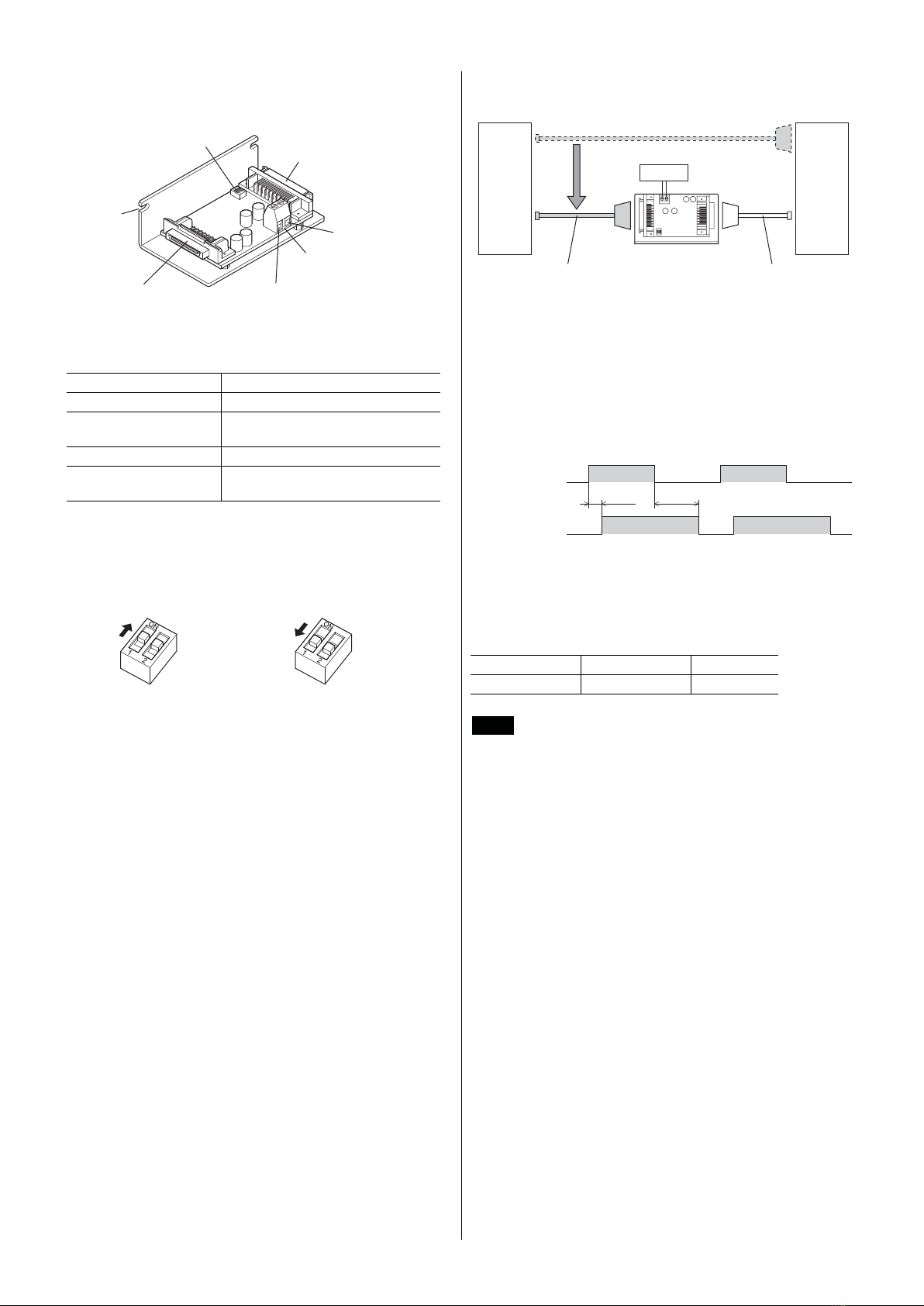
Overview of the product
The pulse line filter, which can be used in connection between the
photocoupler input type driver (such as the stepping motor and
driver package ARL Series, RK Series or other products) and
controller, is a circuit to strengthen the noise-immunity in the pulse
line.
Hazardous substances
RoHS (Directive 2002/95/EC 27Jan.2003) compliant
Safety precautions
The precautions described below are intended to prevent danger or
injury to the user and other personnel through safe, correct use of the
product. Use the product only after carefully reading and fully
understanding these instructions.
Warning
Handling the product without observing the instructions that
accompany a "Warning" symbol may result in serious injury or
death.
• Do not use the product in explosive or corrosive environments, in
the presence of flammable gases, locations subjected to splashing
water, or near combustibles. Doing so may result in fire, electric
shock or injury.
• Assign qualified personnel the task of installing, wiring,
operating/controlling, inspecting and troubleshooting the product.
Failure to do so may result in fire, electric shock, injury or damage
to equipment.
• Install the pulse line filter in the enclosure in order to prevent
electric shock.
• Connect the cables securely according to the wiring diagram.
Failure to do so may result in fire or electric shock.
• For the power supply, use a DC power supply with reinforced
insulation on its primary and secondary sides. Failure to do so
may result in electric shock.
• Do not disassemble or modify the pulse line filter. This may cause
electric shock or injury. Refer all such internal inspections and
repairs to the branch or sales office from which you purchased the
product.
Caution
Handling the product without observing the instructions that
accompany a “Caution” symbol may result in injury or property
damage.
• Do not use the pulse line filter beyond its specifications, or
electric shock, injury or damage to equipment may result.
• Keep the area around the pulse line filter free of combustible
materials in order to prevent fire or a skin burn(s).
• Take measures against static electricity when installing the pulse
line filter. Failure to do so may result in damage to equipment.
• Immediately when trouble has occurred, stop running and turn off
the pulse line filter power. Failure to do so may result in fire or
injury.
• To dispose of the pulse line filter, disassemble it into parts and
components as much as possible and dispose of individual
parts/components as industrial waste.
Preperation
Checking the product
Verify that the items listed below are included. Report any missing
or damaged items to the branch or sales office from which you
purchased the product.
Model name Main applicable
products Packing list
VCS05-11
VCS05-1 .......................1 unit
Connector cable............1 pc.
OPERATING MANUAL
(this document) .............1 copy
VCS05-12
ARL Series
AS Series
ASC Series
VCS05-1 .......................1 unit
Connector (28 pins) ......1 pc.
Connector (36 pins) ......1 pc.
OPERATING MANUAL
(this document) .............1 copy
VCS05-21
VCS05-2 .......................1 unit
Connector cable............1 pc.
OPERATING MANUAL
(this document) .............1 copy
VCS05-22
RK Series VCS05-2 .......................1 unit
Connector (20 pins) ......1 pc.
Connector (28 pins) ......1 pc.
OPERATING MANUAL
(this document) .............1 copy
• Connector (20 pins):
54331-1201 (Molex), 54306-2019(Molex)
• Connector (28 pins):
PCS-E28LB (HONDA TSUSHIN KOGYO CO., LTD.)
PCR-E28FS+ (HONDA TSUSHIN KOGYO CO., LTD.)
• Connector (36 pins):
54331-1361 (Molex), 54306-3619 (Molex)

2
Names and functions of parts
CN1
Controller connecting
terminal
CN3
Driver connecting
terminal
Cutouts for
installation
SW1
Input circuit selector switch
(Factory setting: ON)
CN2
24 VDC connecting terminal
[Terminal tightening torque:
0.5 to 0.6 N·m (71 to 85 oz-in)]
Connect to GND
Connect to
24 VDC
Power supply specifications
Power supply voltage 24 VDC±10%
Current capacity 30 mA
Applicable crimp terminal AI0.25-8YE (PHOENIX CONTACT
GmbH & Co. KG)
Applicable lead wire AWG24 (0.25 mm2)
Applicable crimp tool CRIMPFOX 6 (PHOENIX CONTACT
GmbH & Co. KG)
Switching of input circuit
Based on the specification of the connecting controller, switch the
input circuit of the pulse line filter using SW1.
ON
OFF
Set the SW1-1
and 2 to ON.
•Line driver output •Open-collector output
Set the SW1-1
and 2 to OFF.
ON
OFF
System configuration
DriverController
Pulse line filter
Connection cable between
driver and controller
(The same cable can be used.)
24 VDC
Connect using the provided
cable or connector.
Connection cable between
driver and controller
For connection with a controller, use a shielded cable of AWG28
(0.08 mm2) or thicker.
Delay of the output pulse by the pulse line
filter
The output pulse of the pulse line filter will be delayed 0.8 μs at the
rising edge and 1.8 μs at the falling edge against the input pulse.
1.8 μs0.8 μs
Input pulse
Output pulse
ON
OFF
ON
OFF
The connecting driver will not be able to operate up to the maximum
response frequency due to this delay time. The maximum value that
can be input to the pulse line filter will vary depending on each
driver. Use each driver at a speed that is slower than the following
frequency.
Series name ARL/AS/ASC RK
Frequency (kHz) 150 [250] ∗130 [200]
∗
∗ [ ]: Driver's maximum response frequency
Note When driving up to the driver's maximum response
frequency, use a controller which ON time of the output
pulse is 1 to 1.5 μs.

3
Connection
Connection example of ARL Series, AS Series and ASC Series
• VCS05-11: When using the open-collector output type controller
Connect using the provided connector cable.
CCW
CW
CCW
CW
BSG2
∗6
ASG2
∗6
ACL
ALARM
TIM.2
∗6
END
×10
C.OFF
BSG2
ASG2
ACL
ALARM
TIM.2
END
×10
C.OFF
CN2
CN1 CN3
0 V
V
0
(5 to 24 VDC)
165 Ω
Controller
24 VDC
Pulse line filter VCS05-1 ARL/AS/ASC Series Driver
0 V
0 V
CCW
pulse
CW
pulse
165 Ω
165 Ω
R
∗5
R
∗5
165 Ω
CCW pulse
CW pulse
+24 V
∗4
+24 V
GND
∗4
GND
CCW
CW
Vcc+24 V
GND
CCW
CW
BSG1
GND
ASG1
GND
BSG2
∗6
ASG2
∗6
ACL
TIM.1
GND
ALARM
TIM.2
∗6
END
×10
C.OFF
+24 V
V
0
(5 to 24 VDC)
1
2
1
2
3
4
5
6
7
8
9
10
11
12
13
14
15
16
17
18
19
20
21
22
23
24
25
26
27
28
2
3
9
10
11
12
2
3
9
10
11
12
13
14
15
16
17
18
19
20
21
22
23
24
25
26
27
28
29
30
31
32
33
34
BSG1
GND
ASG1
GND
BSG2
ASG2
ACL
∗2
TIM.1
GND
ALARM
TIM.2
END
×10
∗2
C.OFF
∗2
∗1
∗3
13
14
15
16
17
18
19
20
21
22
23
24
25
26
27
28
29
30
31
32
33
34
ARL/AS Series: CN4
ASC Series: CN3
∗1 Wiring distance is 2 m (6.6 ft.) or shorter. However, if the controller is the line driver output type when connecting the pulse signal only, you can extend
up to 10 m (32.8 ft.).
∗2 Do not connect the ACL input, ×10 input and C.OFF input.
∗3 Wiring distance is 0.5 m (1.6 ft.) or shorter when using the provided cable. However, when connecting the pulse signal only, you can extend up to 10 m.
(32.8 ft.)
∗4 When inputting the power supply to the pin No.2 and No.3 of the CN1, it is no need to connect the power supply to the CN2.
∗5 The CW input and CCW input are both 5 VDC specification. If the power supply voltage exceeds 5 VDC, connect an external resistor R to keep the input
current to 7 to 20 mA.
Example) When V0is 24 VDC R: 1.5 to 2.2 k, 0.5 W or more.
∗6 The ASC Series does not have these signals.

4
• VCS05-11: When using the line driver output type controller
Connect using the provided connector cable.
165 Ω
Controller
24 VDC
Pulse line filter VCS05-1 ARL/AS/ASC Series Driver
0 V
CCW pulse
CW pulse
165 Ω
165 Ω165 Ω
CCW pulse
CW pulse
+24 V
GND
CCW
CCW
CW
CW
Vcc+24 V
GND
CCW
CCW
CW
CW
BSG1
GND
ASG1
GND
BSG2 ∗5
BSG2 ∗5
ASG2 ∗5
ASG2 ∗5
ACL
ACL
TIM.1
GND
ALARM
ALARM
TIM.2 ∗5
TIM.2 ∗5
END
END
×10
×10
C.OFF
C.OFF
+24 V
1
2
1
2
3
4
5
6
7
8
9
10
11
12
13
14
15
16
17
18
19
20
21
22
23
24
25
26
27
28
2
3
9
10
11
12
2
3
9
10
11
12
13
14
15
16
17
18
19
20
21
22
23
24
25
26
27
28
29
30
31
32
33
34
BSG1
GND
ASG1
GND
BSG2
BSG2
ASG2
ASG2
ACL ∗2
ACL
TIM.1
GND
ALARM
ALARM
TIM.2
TIM.2
END
END
×10 ∗2
×10
C.OFF ∗2
∗1
∗3
C.OFF
13
14
15
16
17
18
19
20
21
22
23
24
25
26
27
28
29
30
31
32
33
34
+24 V ∗4
GND ∗4
CN2
CN1 CN3
ARL/AS Series: CN4
ASC Series: CN3
∗1 Wiring distance is 2 m (6.6 ft.) or shorter. However, if the controller is the line driver output type when connecting the pulse signal only, you can extend
up to 10 m (32.8 ft.).
∗2 Do not connect the ACL input, ×10 input and C.OFF input.
∗3 Wiring distance is 0.5 m (1.6 ft.) or shorter when using the provided cable. However, when connecting the pulse signal only, you can extend up to 10 m.
(32.8 ft.)
∗4 When inputting the power supply to the pin No.2 and No.3 of the CN1, it is no need to connect the power supply to the CN2.
∗5 The ASC Series does not have these signals.
• When using the VCS05-12
Connect using the provided connector.
The pin arrangement is shown as viewed
from the solder side.
2
1
20
1936
35
18
17
CN1
CN3
14
28
2
16
15
27
1
13

5
Connection example of RK Series
• VCS05-21: When using the open-collector output type controller
Connect using the provided connector cable.
0 V
V
0
(5 to 24 VDC)
0 V
V
0
(5 to 24 VDC)
165 Ω
Controller
24 VDC
Pulse line filter VCS05-2 RK Series Driver
CW
pulse
CCW
pulse
165 Ω
165 Ω
R ∗4
R ∗4165 Ω
CW pulse
CCW pulse
+CW
-
CW
+CCW
-
CCW
+CW
-
CW
+CCW
-
CCW
+TIM.
-
TIM.
+M.B.FREE ∗3
-
M.B.FREE ∗3
+C/S
-
C/S
+A.W.OFF
-
A.W.OFF
+O.H.
-
O.H.
1
2
1
2
1
2
3
4
5
6
7
8
9
10
17
18
19
20
3
4
5
6
7
8
9
10
17
18
19
20
1
2
3
4
5
6
7
8
9
10
17
18
19
20
∗1
∗2
CN2
CN1 CN1CN3
+TIM.
-
TIM.
+M.B.FREE
-
M.B.FREE
+C/S
-
C/S
+A.W.OFF
-
A.W.OFF
+O.H.
-
O.H.
∗1 Wiring distance is 2 m (6.6 ft.) or shorter. However, if the controller is the line driver output type when connecting the pulse signal only, you can extend
up to 10 m (32.8 ft.).
∗2 Wiring distance is 0.5 m (1.6 ft.) or shorter when using the provided cable. However, when connecting the pulse signal only, you can extend up to 10 m.
(32.8 ft.)
∗3 Connect when using the electromagnetic brake motor.
∗4 The CW input and CCW input are both 5 VDC specification. If the power supply voltage exceeds 5 VDC, connect an external resistor R to keep the input
current to 7 to 20 mA.
Example) When V0is 24 VDC R: 1.5 to 2.2 k, 0.5 W or more.

6
• VCS05-21: When using the line driver output type controller
Connect using the provided connector cable.
165 Ω
Controller
24 VDC
Pulse line filter VCS05-2 RK Series Driver
CW pulse
CCW pulse
165 Ω
165 Ω165 Ω
CW pulse
CCW pulse
+CW
-
CW
+CCW
-
CCW
+CW
-
CW
+CCW
-
CCW
+TIM.
-
TIM.
+M.B.FREE
∗3
-
M.B.FREE
∗3
+C/S
-
C/S
+A.W.OFF
-
A.W.OFF
+O.H.
-
O.H.
1
2
1
2
1
2
3
4
5
6
7
8
9
10
17
18
19
20
3
4
5
6
7
8
9
10
17
18
19
20
1
2
3
4
5
6
7
8
9
10
17
18
19
20
∗1
∗2
CN2
CN1 CN1CN3
+TIM.
-
TIM.
+M.B.FREE
-
M.B.FREE
+C/S
-
C/S
+A.W.OFF
-
A.W.OFF
+O.H.
-
O.H.
∗1 Wiring distance is 2 m (6.6 ft.) or shorter. However, if the controller is the line driver output type when connecting the pulse signal only, you can extend
up to 10 m (32.8 ft.).
∗2 Wiring distance is 0.5 m (1.6 ft.) or shorter when using the provided cable. However, when connecting the pulse signal only, you can extend up to 10 m.
(32.8 ft.)
∗3 Connect when using the electromagnetic brake motor.
• When using the VCS05-22
Connect using the provided connector.
The pin arrangement is shown as viewed
from the solder side.
2
1
12
1120
19
10
9
CN1
CN3
14
28
2
16
15
27
1
13
is a registered trademark or trademark of
Oriental Motor Co., Ltd., in Japan and other countries.
© Copyright ORIENTAL MOTOR CO., LTD. 2011
• Please contact your nearest Oriental Motor office for further information.
Headquarters Tokyo, Japan
Tel:03-6744-0361 Fax:03-5826-2576
Tel:01 47 86 97 50 Fax:01 47 82 45 16
Tel:(02)8228-0707 Fax:(02)8228-0708
Technical Support Tel:(800)468-3982
8:30
A.M.
to 5:00
P.M.
, P.S.T. (M-F)
7:30
A.M.
to 5:00
P.M.
, C.S.T. (M-F)
E-mail: techsupport@orientalmotor.com
www.orientalmotor.com
Headquarters and Düsseldorf Office Tel:0211-52067-00 Fax:0211-52067-099
Munich Office Tel:089-3181225-00 Fax:089-3181225-25
Hamburg Office Tel:040-76910443 Fax:040-76910445
Tel:01256-347090 Fax:01256-347099
Tel:02-93906346 Fax:02-93906348
Tel:+65-6745-7344 Fax:+65-6745-9405
KOREA
Tel:080-777-2042 Fax:02-2026-5495
Tel:(03)22875778 Fax:(03)22875528
Tel:+66-2-251-1871 Fax:+66-2-251-1872
Tel:400-820-6516 Fax:021-6278-0269
Technical Support Tel:(800)468-3982
8:30 A.M. to 5:00 P.M., P.S.T. (M-F)
7:30 A.M. to 5:00 P.M., C.S.T. (M-F)
www.orientalmotor.com
Headquarters Düsseldorf, Germany
Technical Support Tel:00 800/22 55 66 22
www.orientalmotor.de
Tel:01256-347090
www.oriental-motor.co.uk
Tel:01 47 86 97 50
www.orientalmotor.fr
Tel:02-93906346
www.orientalmotor.it
Tel:0800-060708
www.orientalmotor.com.tw
Singapore
Tel:1800-8420280
www.orientalmotor.com.sg
Tel:1800-806161
www.orientalmotor.com.my
Korea
Tel:080-777-2042
www.inaom.co.kr
Headquarters Tokyo, Japan
Tel:03-6744-0361
www.orientalmotor.co.jp
Tel:1800-888-881
www.orientalmotor.co.th
Tel:400-820-6516
www.orientalmotor.com.cn
Tel:+55-11-3266-6018
www.orientalmotor.com.br
Tel:+91-80-41125586
www.orientalmotor.co.in
Hong Kong Branch
Tel:+852-2427-9800
• Please contact your nearest Oriental Motor oce for further information.
This manual suits for next models
4
Table of contents
Other Oriental motor Water Filtration System manuals
Popular Water Filtration System manuals by other brands

3M
3M DIDF260-CL Installation and operation instruction

BWT
BWT bestcamp Mini Installation and service manual

Pfeiffer Vacuum
Pfeiffer Vacuum OME 40S operating instructions

Pall
Pall 5017 Instructions for use

PREMIER TECH
PREMIER TECH Ecoflo EL30 Series owner's manual

Whirlpool
Whirlpool WHEMB40 Installation and operation manual

Prio
Prio Bravo user guide

Growonix
Growonix XL-SCRUB owner's manual

A.O. Smith
A.O. Smith AO-4000-CARBON Replacement manual

Wateranywhere
Wateranywhere AAA-RO200W MANUAL FOR INSTALLATION, OPERATION AND MAINTENANCE

GE
GE PNRV12ZBL01 owner's manual

Watts
Watts PWDWLCV2 Pure Water Installation, operation and maintenance manual