ORiNOCO AP-9000R Manual

ORiNOCO®AP-9200R
(Outdoor Access Point)
Hardware Installation Guide

ORiNOCO® AP-9200R - Hardware Installation Guide 2
Copyright
© 2021 Proxim Wireless Corporation, San Jose, CA. All rights reserved. Covered by one or more of the following U.S. patents: 5,231,634;
5,875,179; 6,006,090; 5,809,060; 6,075,812; 5,077,753. The content described herein are copyrighted with all rights reserved. No part of this
publication may be reproduced, transmitted, transcribed, stored in a retrieval system, or translated into any language in any form by any means
without the written permission of Proxim Wireless Corporation.
Trademarks
ORiNOCO®, Proxim®, and the Proxim logo are the trademarks of Proxim Wireless Corporation. All other trademarks mentioned herein are the
property of their respective owners.
Disclaimer
Proxim reserves the right to revise this publication and to make changes in content from time-to-time without obligation on the part of Proxim to
provide notification of such revision or change. Proxim may make improvements or changes in the product(s) described in this guide at any time.
When using these devices, basic safety precautions should always be followed to reduce the risk of fire, electric shock and injury to persons.
GPL License Note
ORiNOCO®products include, in part, some free software that is developed by Free Software Foundation. A user is granted license to this software
under the terms of either the GNU General Public License or GNU Lesser General Public License (See http://www.gnu.org/licenses/
licenses.html). This license allows the user to freely copy, modify and redistribute this software and no other statement or documentation from
us. To get a copy of this software, or for any other information, please contact our customer support team Telephone Support).
OpenSSL License Note
ORiNOCO®products contains software developed by the OpenSSL Project for use in the OpenSSL Toolkit (http://www.openssl.org/) and that is
subject to the following copyright and conditions:
Copyright (c) 1998-2002 The OpenSSL Project. All rights reserved.
The names “OpenSSL Toolkit” and “OpenSSL Project” must not be used to refer to, endorse, or promote the products or for any other purpose
related to the products without prior written permission. For written permission, please contact openssl-core@openssl.org.
This software is provided by the OpenSSL Project “as is” and any expressed or implied warranties, including, but not limited to, the implied
warranties of merchantability and fitness for a particular purpose are disclaimed. In no event shall the OpenSSL Project or its contributors be liable
for any direct, indirect, incidental, special, exemplary, or consequential damages (including, but not limited to, procurement of substitute goods or
services; loss of use, data, or profits; or business interruption) however caused and on any theory of liability, whether in contract, strict liability, or
tort (including negligence or otherwise) arising in any way out of the use of this software, even if advised of the possibility of such damage.
ORiNOCO® AP-9200R - Hardware Installation Guide
Documentation Version: 1.0
P/N 765-00397, April 2021

ORiNOCO®AP-9200R - Hardware Installation Guide 3
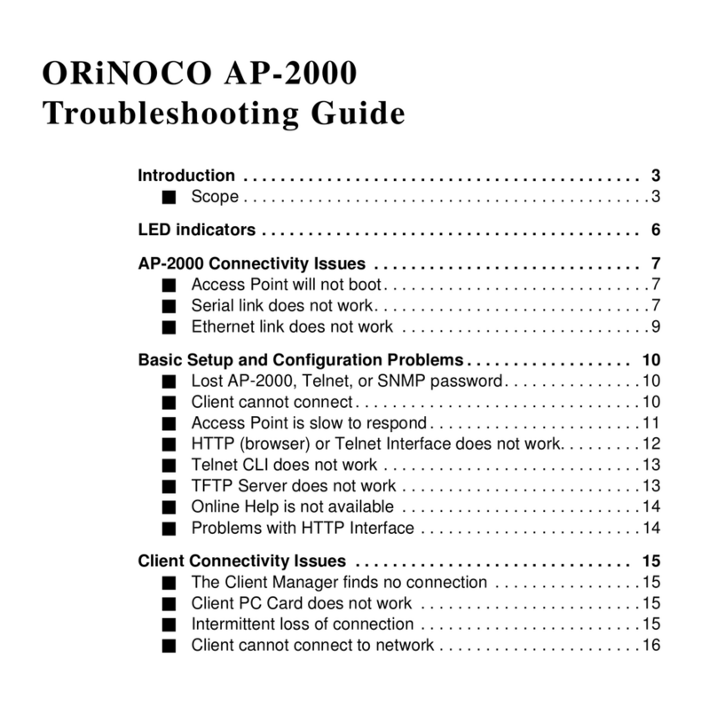
1 Package Contents . . . . . . . . . . . . . . . . . . . . . . . . . . . . . . . . . . . . . . . . . . . . . . . . . . . . . . . . . . . . . 5
2 Getting Started . . . . . . . . . . . . . . . . . . . . . . . . . . . . . . . . . . . . . . . . . . . . . . . . . . . . . . . . . . . . . . . 7
Power-Up . . . . . . . . . . . . . . . . . . . . . . . . . . . . . . . . . . . . . . . . . . . . . . . . . . . . . . . . . . . . . . . . . . . . . . . . . . . 7
Pre-Installation Check List . . . . . . . . . . . . . . . . . . . . . . . . . . . . . . . . . . . . . . . . . . . . . . . . . . . . . . . . . . . . . . . 7
3 Device Overview . . . . . . . . . . . . . . . . . . . . . . . . . . . . . . . . . . . . . . . . . . . . . . . . . . . . . . . . . . . . . . 8
ORiNOCO® AP-9200R Hardware Overview . . . . . . . . . . . . . . . . . . . . . . . . . . . . . . . . . . . . . . . . . . . . . . . . . . 8
Gigabit Ethernet Ports . . . . . . . . . . . . . . . . . . . . . . . . . . . . . . . . . . . . . . . . . . . . . . . . . . . . . . . . . . . . . . . . . . . . . . . . 9
Grounding Points . . . . . . . . . . . . . . . . . . . . . . . . . . . . . . . . . . . . . . . . . . . . . . . . . . . . . . . . . . . . . . . . . . . . . . . . . . . 9
4 Device Installation . . . . . . . . . . . . . . . . . . . . . . . . . . . . . . . . . . . . . . . . . . . . . . . . . . . . . . . . . . . 10
Installation Procedure . . . . . . . . . . . . . . . . . . . . . . . . . . . . . . . . . . . . . . . . . . . . . . . . . . . . . . . . . . . . . . . . . 10
5 Technical Specifications . . . . . . . . . . . . . . . . . . . . . . . . . . . . . . . . . . . . . . . . . . . . . . . . . . . . . . . 16
Device Models . . . . . . . . . . . . . . . . . . . . . . . . . . . . . . . . . . . . . . . . . . . . . . . . . . . . . . . . . . . . . . . . . . . . . . . 16
Accessories . . . . . . . . . . . . . . . . . . . . . . . . . . . . . . . . . . . . . . . . . . . . . . . . . . . . . . . . . . . . . . . . . . . . . . . . . 16
OFDM Modulation Rates . . . . . . . . . . . . . . . . . . . . . . . . . . . . . . . . . . . . . . . . . . . . . . . . . . . . . . . . . . . . . . . 17
Wireless Protocol . . . . . . . . . . . . . . . . . . . . . . . . . . . . . . . . . . . . . . . . . . . . . . . . . . . . . . . . . . . . . . . . . . . . . 18
Interfaces . . . . . . . . . . . . . . . . . . . . . . . . . . . . . . . . . . . . . . . . . . . . . . . . . . . . . . . . . . . . . . . . . . . . . . . . . . 18
Transmit Power Specifications (5.150 to 5.850) GHz . . . . . . . . . . . . . . . . . . . . . . . . . . . . . . . . . . . . . . . . . . 19
Transmit Power Specifications (2.400 to 2.484) GHz . . . . . . . . . . . . . . . . . . . . . . . . . . . . . . . . . . . . . . . . . . 20
Receive Sensitivity (5.150 - 5.850) GHz . . . . . . . . . . . . . . . . . . . . . . . . . . . . . . . . . . . . . . . . . . . . . . . . . . . . 20
Receive Sensitivity (2.400 to 2.484) GHz . . . . . . . . . . . . . . . . . . . . . . . . . . . . . . . . . . . . . . . . . . . . . . . . . . . 21
Power Supply . . . . . . . . . . . . . . . . . . . . . . . . . . . . . . . . . . . . . . . . . . . . . . . . . . . . . . . . . . . . . . . . . . . . . . . 22
Hardware Specifications . . . . . . . . . . . . . . . . . . . . . . . . . . . . . . . . . . . . . . . . . . . . . . . . . . . . . . . . . . . . . . . 22
Physical Specifications . . . . . . . . . . . . . . . . . . . . . . . . . . . . . . . . . . . . . . . . . . . . . . . . . . . . . . . . . . . . . . . . . 22
Environmental Specifications . . . . . . . . . . . . . . . . . . . . . . . . . . . . . . . . . . . . . . . . . . . . . . . . . . . . . . . . . . . . 22
MTBF . . . . . . . . . . . . . . . . . . . . . . . . . . . . . . . . . . . . . . . . . . . . . . . . . . . . . . . . . . . . . . . . . . . . . . . . . . . . . . 23
7 Recommended Antennas . . . . . . . . . . . . . . . . . . . . . . . . . . . . . . . . . . . . . . . . . . . . . . . . . . . . . . 24
Introduction to Antennas . . . . . . . . . . . . . . . . . . . . . . . . . . . . . . . . . . . . . . . . . . . . . . . . . . . . . . . . . . . . . . . 24
Antennas Supported . . . . . . . . . . . . . . . . . . . . . . . . . . . . . . . . . . . . . . . . . . . . . . . . . . . . . . . . . . . . . . . . . . 24
Flat Panel Antennas . . . . . . . . . . . . . . . . . . . . . . . . . . . . . . . . . . . . . . . . . . . . . . . . . . . . . . . . . . . . . . . . . . . . . . . . . 24
Sector Antennas . . . . . . . . . . . . . . . . . . . . . . . . . . . . . . . . . . . . . . . . . . . . . . . . . . . . . . . . . . . . . . . . . . . . . . . . . . . 24
Supplied Antenna Specifications . . . . . . . . . . . . . . . . . . . . . . . . . . . . . . . . . . . . . . . . . . . . . . . . . . . . . . . . . 25
Recommended Antennas . . . . . . . . . . . . . . . . . . . . . . . . . . . . . . . . . . . . . . . . . . . . . . . . . . . . . . . . . . . . . . . 28
Recommended Antenna Specifications . . . . . . . . . . . . . . . . . . . . . . . . . . . . . . . . . . . . . . . . . . . . . . . . . . . . 28
Sector Antenna Specifications . . . . . . . . . . . . . . . . . . . . . . . . . . . . . . . . . . . . . . . . . . . . . . . . . . . . . . . . . . . . . . . . . 28
14 dBi Dual Polarized Sector Antenna. . . . . . . . . . . . . . . . . . . . . . . . . . . . . . . . . . . . . . . . . . . . . . . . . . . . . . . . . 29

ORiNOCO®AP-9200R - Hardware Installation Guide 4
15.5 dBi Dual Polarized Sector Antenna . . . . . . . . . . . . . . . . . . . . . . . . . . . . . . . . . . . . . . . . . . . . . . . . . . . . . . . 31
Panel Antenna Specifications . . . . . . . . . . . . . . . . . . . . . . . . . . . . . . . . . . . . . . . . . . . . . . . . . . . . . . . . . . . . . . . . . . 33
23 dBi Dual Polarized Panel Antenna . . . . . . . . . . . . . . . . . . . . . . . . . . . . . . . . . . . . . . . . . . . . . . . . . . . . . . . . . 33
29 dBi Dual Polarized Panel Antenna . . . . . . . . . . . . . . . . . . . . . . . . . . . . . . . . . . . . . . . . . . . . . . . . . . . . . . . . . 35
19 dBi Quad Polarized Panel Antenna. . . . . . . . . . . . . . . . . . . . . . . . . . . . . . . . . . . . . . . . . . . . . . . . . . . . . . . . . 37
8 Antenna Installation . . . . . . . . . . . . . . . . . . . . . . . . . . . . . . . . . . . . . . . . . . . . . . . . . . . . . . . . . . 40
Safety Precautions . . . . . . . . . . . . . . . . . . . . . . . . . . . . . . . . . . . . . . . . . . . . . . . . . . . . . . . . . . . . . . . . . . . . 40
Installation Process . . . . . . . . . . . . . . . . . . . . . . . . . . . . . . . . . . . . . . . . . . . . . . . . . . . . . . . . . . . . . . . . . . . 40
Required Materials. . . . . . . . . . . . . . . . . . . . . . . . . . . . . . . . . . . . . . . . . . . . . . . . . . . . . . . . . . . . . . . . . . . . . . . . . . 41
Determining the Optimal Antenna Placement . . . . . . . . . . . . . . . . . . . . . . . . . . . . . . . . . . . . . . . . . . . . . . . . . . . . . 42
Mounting the Antenna . . . . . . . . . . . . . . . . . . . . . . . . . . . . . . . . . . . . . . . . . . . . . . . . . . . . . . . . . . . . . . . . . . . . . . 43
Antenna Mast Requirements . . . . . . . . . . . . . . . . . . . . . . . . . . . . . . . . . . . . . . . . . . . . . . . . . . . . . . . . . . . . . . . 43
Antenna Tilt Angles and corresponding EIRP values . . . . . . . . . . . . . . . . . . . . . . . . . . . . . . . . . . . . . . . . . . . . . . 43
Connecting the Cables . . . . . . . . . . . . . . . . . . . . . . . . . . . . . . . . . . . . . . . . . . . . . . . . . . . . . . . . . . . . . . . . . . . . . . 47
Connecting the Antenna Cable . . . . . . . . . . . . . . . . . . . . . . . . . . . . . . . . . . . . . . . . . . . . . . . . . . . . . . . . . . . . . 47
Connecting the Surge Arrestor and Ethernet / Power cables . . . . . . . . . . . . . . . . . . . . . . . . . . . . . . . . . . . . . . . . 48
Grounding the System . . . . . . . . . . . . . . . . . . . . . . . . . . . . . . . . . . . . . . . . . . . . . . . . . . . . . . . . . . . . . . . . . . . . 49
Sealing the Cable Connectors . . . . . . . . . . . . . . . . . . . . . . . . . . . . . . . . . . . . . . . . . . . . . . . . . . . . . . . . . . . . . . . . . 49
9 Measuring Signal Performance . . . . . . . . . . . . . . . . . . . . . . . . . . . . . . . . . . . . . . . . . . . . . . . . . 53
Introduction . . . . . . . . . . . . . . . . . . . . . . . . . . . . . . . . . . . . . . . . . . . . . . . . . . . . . . . . . . . . . . . . . . . . . . . . 53
Determining the Range . . . . . . . . . . . . . . . . . . . . . . . . . . . . . . . . . . . . . . . . . . . . . . . . . . . . . . . . . . . . . . . . 53
Fresnel Zone . . . . . . . . . . . . . . . . . . . . . . . . . . . . . . . . . . . . . . . . . . . . . . . . . . . . . . . . . . . . . . . . . . . . . . . . 53
Fresnel Zone Calculation . . . . . . . . . . . . . . . . . . . . . . . . . . . . . . . . . . . . . . . . . . . . . . . . . . . . . . . . . . . . . . . . . . . . . 54
Clearance Factor . . . . . . . . . . . . . . . . . . . . . . . . . . . . . . . . . . . . . . . . . . . . . . . . . . . . . . . . . . . . . . . . . . . . . 55
Calculations . . . . . . . . . . . . . . . . . . . . . . . . . . . . . . . . . . . . . . . . . . . . . . . . . . . . . . . . . . . . . . . . . . . . . . . . . 56
Calculating Link Budget. . . . . . . . . . . . . . . . . . . . . . . . . . . . . . . . . . . . . . . . . . . . . . . . . . . . . . . . . . . . . . . . . . . . . . 56
A Lightning Protection . . . . . . . . . . . . . . . . . . . . . . . . . . . . . . . . . . . . . . . . . . . . . . . . . . . . . . . . . . 60
B Abbreviations . . . . . . . . . . . . . . . . . . . . . . . . . . . . . . . . . . . . . . . . . . . . . . . . . . . . . . . . . . . . . . . 61
C Warranty and Technical Support . . . . . . . . . . . . . . . . . . . . . . . . . . . . . . . . . . . . . . . . . . . . . . . . 62
Obtaining Technical Service and Support . . . . . . . . . . . . . . . . . . . . . . . . . . . . . . . . . . . . . . . . . . . . . . . . . . . 62
Support Options . . . . . . . . . . . . . . . . . . . . . . . . . . . . . . . . . . . . . . . . . . . . . . . . . . . . . . . . . . . . . . . . . . . . . 62
Additional Information on ServPak Options . . . . . . . . . . . . . . . . . . . . . . . . . . . . . . . . . . . . . . . . . . . . . . . . . 63
D Safety & Regulatory Information . . . . . . . . . . . . . . . . . . . . . . . . . . . . . . . . . . . . . . . . . . . . . . . 65

ORiNOCO®AP-9200R - Hardware Installation Guide 5
1
Package Contents
Each shipment includes the items listed in the following table. Please verify that you have received all the parts in this
shipment, prior to installation.
What’s in the kit Image
AP9200R
Power Injector with Country
specific Power Cord
WD - US and EU power cords
US - US power cord
2.4 GHz, 7 dBi Omni Antennas
(x 3)
5 GHz, 7 dBi Omni Antennas (x 4)
Connector Weather Proofing Kit
(1 set)
Grounding Kit

Package Contents
ORiNOCO®AP-9200R - Hardware Installation Guide 6
Mounting Kit and Hardware The mounting kit includes the following:
Full axis mounting kit
Quick Installation Guide
What’s in the kit Image

ORiNOCO®AP-9200R - Hardware Installation Guide 7
2
Getting Started
2.1 Power-Up
To Power on the device, perform the following steps:
1. Connect the OUT / POE port on the PoE and the Ethernet Port of the device using a standard Cat5e cable
terminated with RJ45 connectors.
2. Connect the IN / LAN port on the PoE and the NIC port of a computer.
3. Connect the AC power cord to PoE and switch ON the AC power.
4. The LEDs on the RJ45 port of the device glows.
5. Ping the device’s IP Address to check the network connectivity. (Please refer QIG for IP Address of the device)
6. If the ping is successful, continue with the installation process.
The device receives (36 - 57) V DC via a a standard Cat5e cable connected between the PoE and the device.
1.
: Due to DC power requirements, the maximum cable length between the PoE Injector and the device should be
less than 100 meters.
Prior to the Pole Mounting or Wall Mounting procedure, it is always recommended to check the functionality by powering on
the device with the temporary connections.
2.2 Pre-Installation Check List
It is mandatory to check the Safety & Regulatory Information before you perform the Installation procedure.
You will need the following tools to perform the Installation:
10mm Spanner #2 Philips Screw Driver
#3 Philips Screw Driver Crimping Tool

ORiNOCO®AP-9200R - Hardware Installation Guide 8
3
Device Overview
This section provides the hardware overview and installation procedure for the following product(s):
•AP-9200R
3.1 ORiNOCO®AP-9200R Hardware Overview
Figure 3-1 AP9200R
The features of the above devices are tabulated as below:
A detailed description about the various components of the device are explained in the following sections.
Device Model Description
AP-9200R ORiNOCO®AP-9200R, MU-MIMO 4x4 w2, dual radio, connectorized outdoor Access Point
Item Features Description
1 Ethernet Port • PoE IN and Data
• Debugging and Management
2 Grounding Point • A provision to ground the device.
3 5 GHz Antenna Ports (A1, A2, A3 and A4) • A provision to connect external antenna in MIMO 4x4
mode (supplied).
4 2.4 GHz Antenna Ports (A5, A6 and A7) • A provision to connect external antenna in MIMO 3x3
mode (supplied).
5 RSSI Display • Displays status information (see Status LED Behavior
section).
6 Mounting Holes • A provision to connect 1000-UMK mounting kit
(provided) or 10000-UMK mounting kit (optional).

Device Overview
ORiNOCO®AP-9200R - Hardware Installation Guide 9
3.1.1 Gigabit Ethernet Ports
The device comes with one 1000 BASE-T ethernet port with configurable Tx modes and speeds.
•Ethernet Port/ PoE IN and Data
The Gigabit Ethernet Port (PoE IN and Data) of the device allows the user to connect to the LAN by using Cat5e Ethernet
cable, and also power ON the device by using the Power over Ethernet (PoE) Injector supplied with the product package.
•The device receives (36 - 57) V DC via a STP Cat5e cable connected between the PoE and the device.
•Ethernet Port supports the following features:
1. Auto MDI-X, auto configuration and fixed speed/duplex configurations.
2. Jumbo frames of size up to 9 k bytes.
3.1.2 Grounding Points
To protect the device against lighting or ESD events, you must ground the device properly. To ensure proper grounding, use
the ground point that is situated at the bottom corner of the device and the grounding screw (M4 thread size) provided to
attach a ground wire of at least 12 AWG stranded to the device.
Recommended Ethernet Cable Specifications
Type Cat5e, Cat6, STP, 24 AWG, UL rated, Shielded, UV Resistant and outdoor-rated
Impedance 100 ohms
Cable Length 330 feet / 100 meters
: The total length of cabling between the Personal Computer and the device cannot
exceed 100 meters (includes cable from the Personal Computer to the PoE, and the
cable from the PoE to the device). Due to DC power requirements, the maximum cable
length between the PoE Injector and the device should be less than 100 meters.

ORiNOCO®AP-9200R - Hardware Installation Guide 10
4
Device Installation
4.1 Installation Procedure
This section describes the steps to install and mount the device(s).
: The device must be installed by a trained professional who is familiar with radio frequency planning and
regulatory limits. Please refer Safety & Regulatory Information for details.
Perform the following steps to install and mount the device
Step 1: Plan for Installation
There are several planning factors to be considered before installing the device. In addition to selecting the installation site,
you should do the following:
Determine:
•System frequency plan
•Required antenna mounting height to obtain proper path clearance
•Required transmission line types (like RF cable, waveguides) and lengths
Plan for:
•Device’s continuous power consumption needs
•Lightning protection and system grounding
•Hardware mounting
•Cable installation including ingress
•Pre-testing equipment (back-to-back test)
Step 2: Choose a Location
To make optimal use of the device, you must find a suitable location to install the hardware. The range of the radio device
largely depends upon the position of the antenna. Proxim recommends you do a site survey, observing the following
requirements, before mounting the hardware.
•The location must allow easy disconnection of power to the radio, if necessary.
•Ensure free flow of air around the hardware.
•The radio device must be kept away from vibration and excessive heat.
•The installation must conform to local regulations at all times. For details, please refer to Safety & Regulatory
Information.
The devices are designed to directly mount to a pole. By using the supplied brackets and hardware, you can mount them to
a 1.5 to 3.25 inch pole (outside diameter).

Device Installation
ORiNOCO®AP-9200R - Hardware Installation Guide 11
Step 3: Gather Required Materials
You should have the following materials available before installing the device:
•Weatherproofing material (such as butyl mastic tape and vinyl tape) for sealing external connectors.
•Straight-through UV-protected STP-rated Cat5e Ethernet cable for connecting to PC, or cable for connecting to a hub
or a switch.
•Another straight-through UV-protected STP-rated Cat5e Ethernet cable for connecting the OUT / POE port of PoE and
device.
Step 4: Unpack the Product Package
1. Unpack the device and its accessories from the product package box.
2. Please make a note of the Ethernet addresses, the MAC addresses and the serial number. These addresses may be
used when configuring the device. Note that the serial number helps you to seek support from the Proxim’s Customer
support team.
Step 5: Weatherproofing RJ45 Connection and RP-SMA Connection
1. Use an outdoor rated CAT5e cable with a straight-through terminated on both ends.
2. Insert the CAT5e cable through the Sealing Nut (D) and install the Compression Washer (C) to the cable. Compression
Washer (C) has a slit in the middle for quick installation onto the cable.
3. Install the parts (D) and (C) in the direction as shown in Figure 2.
4. Insert the Flat Washer (A) onto the Connector Body (B) and then insert the CAT5e cable through the Connector Body
(B).
5. Connect the cable end of RJ45 connector into Ethernet port of the device.
6. Make sure that the locking latch of RJ45 Connector is properly inserted into the ethernet port.
7. Fasten the Connector Body Assembly to the Device Ethernet port hole and fully tighten it.
8. Slide and Insert the Compression Washer (C) into the Connector Body Assembly.
9. Fasten the Sealing Nut (D) to the Connector Body Assembly and fully tighten it to weatherproof the cable.
10. Warp Butyl Mastic Tape and Vinyl Tape around the connectors to weatherproof the RP-SMA and antenna connections.
Figure 4-1 Weatherproofing RJ45 Connection
Additional Weatherproofing Steps
To add an additional layer of protection to the connectors against the environment, see Additional Weatherproofing Steps.

Device Installation
ORiNOCO®AP-9200R - Hardware Installation Guide 12
Step 6: Assemble Mounting Hardware
1. Place the L-Shaped Mounting Bracket onto the bottom of the device and align with the four mounting holes.
2. Insert the screws and washers into the four mounting holes as shown in Figure 4-2 view (B).
3. Tighten the screws to the required torque. The last image in Figure 4-2 view (C) shows the fully assembled mounting
hardware attached to the device.
Figure 4-2 Assemble the Mounting Hardware
Step 7: Mount the Device
1. To pole-mount the device to a 1.5 to 3.25 inch diameter pole, place the fully assembled mounting hardware along
with the device against the pole and insert the U-bolt through the holes provided on full axis plate on the Mounting
Bracket.
2. Insert the Toothed Washer, Spring Washer, Flat Washer and Nut on both ends of the U-bolt as shown in Figure 4.
3. Tighten the nut slightly so that the U-bolt is adjustable for pole mounting. After adjusting the angle of the device, fully
tighten the nut.
Figure 4-3 Pole Mounting
Step 8: Plug in the Cables

Device Installation
ORiNOCO®AP-9200R - Hardware Installation Guide 13
1. Plug one end of the straight-through Cat5e cable into the Ethernet Port of the device by following the procedure
explained under Step 5: Weatherproofing RJ45 Connection and RP-SMA Connection. Connect the other end of the
cable into the OUT / POE port on the PoE Injector.
Figure 4-4 Cable Plugged In
2. To connect the device through a hub or a switch to a Personal Computer, connect an Ethernet cable between the
network interface card in the Personal Computer and the hub, and between the hub and the RJ45 IN / LAN port on
the PoE Injector.
3. To connect the device directly to a Personal Computer, connect an Ethernet cable between the network interface card
in the Personal Computer and the RJ45 IN / LAN port on the PoE Injector.
: AP-9200R device is supplied with a 30W passive PoE injector. It can also be powered up via 802.3af/at power injector
or switch.
Step 10: Install Surge Protector
ORiNOCO®AP-9200R Series products comes with a built-in Ethernet surge protection; however, it is mandatory to install an
approved lightning surge protector at the building ingress point. Moreover, if you are installing the device in a region
subjected to violent thunderstorms or severe weather conditions, then installation of an additional approved lightning surge
protector near the device is recommended.
: The Surge Arrestor (Part Number 235-00001) is not provided with the Proxim’s Package Contents, it needs to be
procured by the customer. To buy an additional Surge Protector, place an order separately with your distributor.
Perform the following steps to ensure proper surge protection:
1. Mount a surge protector near the building ingress and use 12 AWG or larger wire to connect the surge protector’s
ground lug to earth ground.
2. The outdoor device and co-located surge protector (optional) should have a common grounding point using the
shortest possible grounding cable.

Device Installation
ORiNOCO®AP-9200R - Hardware Installation Guide 14
Figure 4-5 Surge Protector
: Use Outdoor-rated, UV protected, shielded Cat5e cable for the following:
3. Connect an RJ45 terminated cable between the indoor device and to the port on the surge protector at the building
ingress.
4. Connect an RJ45 terminated cable between the surge protector and the outdoor device on the Ethernet Port.
Step 11: Ground the Unit
To ensure proper grounding, attach a ground wire of at least 12 AWG stranded to the device at the ground point which is
located at the bottom corner of the device and use the grounding screw provided. It is important to follow the grounding
guidelines below to protect the device against lighting or ESD events:
1. Connect one end of the grounding cable to the device and the other end to the closest earth ground point at the
installation site.
2. Remove any extra ground wire length when finished connecting it to the single point earth ground.
3. Avoid sharp bends, loops or coiling the ground wire, always connect it straight to ground.
4. A proper earth ground impedance is less than 1.0 ohm.
5. Measure ground impedance at the point where the surge protector ground wire is connected and not at the
grounding rod.
6. Connect the surge protector ground wire and equipment ground (both power ground and telecomm ground) to a
single common ground.
7. Make sure all connections are fastened securely and tight.
8. Never install a link during a storm and always follow your local safety codes.
Connect the grounding wire, which is supplied with the product package, to the device as shown below:
:Ensure to loop the cable before entering the premise to prevent water ingress.

Device Installation
ORiNOCO®AP-9200R - Hardware Installation Guide 15
.
Figure 4-6 Ground the Device
Step 12: Power ON the Device
After connecting the PoE Injector and the device using straight-through CAT5e cable plug the power cord into a power
outlet. There is no ON/OFF switch on the device. To power down the unit, unplug the RJ45 connector from the OUT / POE
port on the PoE injector.
Step 13: Port LED Indicators
When the device is powered on, it performs startup diagnostics. When startup is complete, the LEDs show the device’s
operational state. The LEDs are located on the Ethernet port inside the device enclosure.
: The LEDs will not be visible when the weather-sealing cap is installed.
The LEDs can be seen at the bottom of the Ethernet port. The following table describes the status of LEDs:
Figure 4-7 Port LED Indicators
LED State Off On
Status LED Ethernet link is down Ethernet link is active
Gigabit LED Ethernet link is established at
100 Mbps
Ethernet link is established at 1 Gbps

ORiNOCO®AP-9200R - Hardware Installation Guide 16
5
Technical Specifications
Device Models
Accessories
Model Part
Number
Description
AP-9200R-US 903-00035 ORiNOCO®AP-9200R, MU-MIMO 4x4 w2, dual radio, connectorized outdoor
Access Point – US Power
AP-9200R-WD 903-00036 ORiNOCO®AP-9200R, MU-MIMO 4x4 w2, dual radio, connectorized outdoor
Access Point – WD Power
AP-9200R-JP 903-00040 ORiNOCO®AP-9200R, MU-MIMO 4x4 w2, dual radio, connectorized outdoor
Access Point – JP Power
AP-9200R-CN 903-00041 ORiNOCO®AP-9200R, MU-MIMO 4x4 w2, dual radio, connectorized outdoor
Access Point – CN Power
Part Numbers CAMCODE Accessories
76955 PA5-0823-DP 4.9 - 5.875 GHz, Dual Polarity, Slanted (±45º) or V/H, 23 dBi Panel Antenna
949-00019 PA5-0530-DP 4.9 - 6.1 GHz, Dual Polarity, Vertical and Horizontal, 30 dBi Panel Antenna
949-00011 SA5-6015-DP 4.9-6GHz, Dual Polarity,Vertical /Horizontal,16.5 dBi Sector Antenna - 60
degrees.Mounting kit Incd.
949-00012 SA5-9014-DP 4.9-5.95GHz, Dual Polarity,Vertical and Horizontal, 14dBi Sector Antenna- 90
degrees. Mounting kit Incd.
949-00027 PA2-1720-DP 2.3-2.7 GHz, Dual Polarity, Vertical & Horizantal, 20 dBi Panel Antenna
949-00152 CBL-240-6-RA 6 ft Low Loss Coaxial Antenna Cable, 0.240", Reverse Polarity SMA Male to
Right Angle N-Male
949-00153 SMA-CAP-50 SMA metal weatherproofing cap with O-ring (fit SMA and RP-SMA
connectors) - 50 pack
400-00036 GIG-POE-INJ-48VDC PoE Gigabit 48V DC Injector with terminal Jack
400-00002 GIG-POE-INJ-48VDC-T PoE Gigabit 48V DC Injector with terminal Jack - 25 pack
949-00140 ETH-POEINJ60-1G-VI Gigabit, 60W, PoE injector with RJ45, level VI Compliance
949-00144 ETH-POEINJ30-1G-VI-v2 Gigabit, 30W, passive PoE injector with RJ45, level VI Compliance
235-00001 ETH-SURGE-1G SURGE, GIGABIT SURGE PROTECTOR WITH SHIELDED RJ45
949-00125 ETH-STP-25-CAP 25m outdoor, RJ45 terminated, UV Rated, STP Shielded CAT5e cable with
M20 and M25 cable gland

Technical Specifications
ORiNOCO®AP-9200R - Hardware Installation Guide 17
OFDM Modulation Rates
Given below are the OFDM modulation rates for the ORiNOCO®products:
949-00150 ETH-STP-50-CAP 50m outdoor, RJ45 terminated, UV Rated, STP Shielded CAT5e cable with
M20 and M25 cable gland
949-00175 ETH-STP-75-CAP 75m outdoor, RJ45 terminated, UV Rated, STP Shielded CAT5e cable with
M20 and M25 cable gland
949-00154 ETH-CAP-M25-25 Cable Feed Thru, M25 Cable Gland Connector for Edge and ORiNOCO®
9200R - 25 pack
949-00155 1000-UMK Outdoor Universal Mounting Kit for Edge and ORiNOCO® 9200R
949-00076 10000-UMK Outdoor Universal Mounting Kit for Tsunami® 800/10100 and outdoor
ORiNOCO® 9100
Radio #1: 5 GHz
Products MCS
Index
Modulation Coding
Rate
Data Rates (Mbps) Per Stream
20 MHz Channels 40 MHz Channels 80 MHz Channels
800ns GI 400ns GI 800nsGI 400ns GI 800ns GI 400ns GI
AP-9200R 0 BPSK 1/2 6.5 7.2 13.5 15 29.3 32.5
1 QPSK 1/2 13 14.4 27 30 58.5 65
2 QPSK 3/4 19.5 21.7 40.5 45 87.8 97.5
3 16QAM 1/2 26 28.9 54 60 117 130
4 16QAM 3/4 39 43.3 81 90 175.5 195
5 64QAM 2/3 52 57.8 108 120 234 260
6 64QAM 3/4 58.5 65 121.5 135 263.3 292.5
7 64QAM 5/6 65 72.2 135 150 292.5 325
8 256-QAM 3/4 78 86.7 162 180 351 390
9 256-QAM 5/6 N/A N/A 180 200 390 433.3
Note: Maximum Packet Size = 9000 Bytes (excluding one VLAN header, Ethernet header and FCS).

Technical Specifications
ORiNOCO®AP-9200R - Hardware Installation Guide 18
Wireless Protocol
Interfaces
Radio #2: 2.4 GHz
Products MCS Index Modulation Coding Rate
Data Rates (Mbps) Per Stream
20 MHz Channels 40 MHz Channels
800ns GI 400ns GI 800ns GI 400ns GI
AP-9200R 0 BPSK 1/2 6.5 7.2 13.5 15
1 QPSK 1/2 13 14.4 27 30
2 QPSK 3/4 19.5 21.7 40.5 45
3 16QAM 1/2 26 28.9 54 60
4 16QAM 3/4 39 43.3 81 90
5 64QAM 2/3 52 57.8 108 120
6 64QAM 3/4 58.5 65 121.5 135
7 64QAM 5/6 65 72.2 135 150
Note: Maximum Packet Size = 9000 Bytes (excluding one VLAN header, Ethernet header and FCS).
Category Specification
Wireless Protocol Radio #1: 802.11a/n/ac
Radio #2: 802.11b/g/n
Products Category Specification
AP-9200R Wired Ethernet Auto MDI-X, auto configuration and fixed
speed/duplex configurations.
One auto MDI-X RJ45 Gigabit Ethernet Port
with PoE IN and Data.

Technical Specifications
ORiNOCO®AP-9200R - Hardware Installation Guide 19
Transmit Power Specifications (5.150 to 5.850) GHz
Products Stream MCS
Index
Modulation
Type
Coding
Rate
Tx Power* (dBm)
VHT20
(5.15-5.80 GHz)
VHT40
(5.15- 5.80 GHz)
VHT80
(5.15- 5.80 GHz)
AP-9200R Single
stream
(or)
Dual
Stream
(or)
Quad
Stream
MCS 0 BPSK 1/2 21 20 18
MCS 1 QPSK 1/2 21 20 18
MCS 2 QPSK 3/4 20 19 18
MCS 3 16QAM 1/2 20 19 18
MCS 4 16QAM 3/4 19 18 18
MCS 5 64QAM 2/3 19 18 17
MCS 6 64QAM 3/4 17 17 17
MCS 7 64QAM 5/6 17 16 16
MCS 8 256-QAM 3/4 16 15 15
MCS 9 256-QAM 5/6 NA 15 14
Note:
•Output Power Attenuation: 0 – 17 dB, in 1 dB steps
•For MCS 0, the maximum attenuation limit is 17 dB
•For MCS 9, the maximum attenuation limit is 10 dB
•Total EIRP must be calculated based on the antenna gain
•Tolerance = +/- 2 dB
* Tx Power indicates the power at the radio ports.
* In case of integrated devices, the Tx Power at the antenna ports is 1 dB higher than the above tabulated values.
•In the FCC United States 5.8 GHz band edge frequencies, the Maximum Tx Power of the radio will be restricted based on the FCC
Certification and Antenna Type used. For details refer the Antenna Intallation and Recommendation Guide.

Technical Specifications
ORiNOCO®AP-9200R - Hardware Installation Guide 20
Transmit Power Specifications (2.400 to 2.484) GHz
Receive Sensitivity (5.150 - 5.850) GHz
2.400 ~ 2.484 GHz
Products Stream MCS Index Modulation
Typ e
Coding
Rate
Tx Power* (dBm)
11n HT20 11n HT40
AP-9200R Single
stream
(or)
Dual
Stream
MCS 0 (or)
MCS 8
BPSK 1/2 21 20
MCS 1 (or)
MCS 9
QPSK 1/2 21 20
MCS 2 (or)
MCS 10
QPSK 3/4 20 19
MCS 3 (or)
MCS 11
16 QAM 1/2 20 19
MCS 4 (or)
MCS 12
16 QAM 3/4 19 18
MCS 5 (or)
MCS 13
64 QAM 2/3 19 18
MCS 6 (or)
MCS 14
64 QAM 3/4 18 17
MCS 7 (or)
MCS 15
64 QAM 5/6 18 17
Note:
Output Power Attenuation: 0 – 17 dB, in 1 dB steps
Total EIRP must be calculated based on the antenna gain
* Tx Power indicates the power at the radio ports.
Products Stream Modulation Type Coding Rate
Receive Sensitivity*
(dBm)
(5.150 ~ 5.850) GHz
VHT20 VHT40 VHT80
AP-9200R Dual Stream BPSK 1/2 -91 -87 -85
QPSK 1/2 -87 -84 -82
QPSK 3/4 -85 -82 -80
16 QAM 1/2 -83 -79 -77
16 QAM 3/4 -78 -75 -73
64 QAM 2/3 -74 -72 -69
64 QAM 3/4 -72 -70 -68
64 QAM 5/6 -70 -67 -67
256QAM 3/4 -68 -64 -62
256QAM 5/6 -66 -62 -59
Note:
•Receive Sensitivity values should be considered with a tolerance +/- 2 dB.
Table of contents
Other ORiNOCO Wireless Access Point manuals
Popular Wireless Access Point manuals by other brands

Beijer Electronics
Beijer Electronics JetWave 4020 Series user manual

Siemens
Siemens SCALANCE W786-x operating instructions

Hawking
Hawking HOD45B Quick installation guide

Compaq
Compaq CP-2W - iPAQ Connection Point user guide

Teletronics International
Teletronics International MiniLink user manual

D-Link
D-Link xtreme n duo dap-1522 Quick installation guide